Material classification by Fast Neutron Scattering Analysis
Material classification by Fast Neutron Scattering Analysis
Material classification by Fast Neutron Scattering Analysis

You also want an ePaper? Increase the reach of your titles
YUMPU automatically turns print PDFs into web optimized ePapers that Google loves.
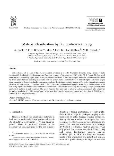
Nuclear Instruments and Methods in Physics Research B 173 (2001) 483±502<br />
www.elsevier.nl/locate/nimb<br />
<strong>Material</strong> classi®cation <strong>by</strong> fast neutron scattering<br />
A. Bu‚er a , F.D. Brooks a, *<br />
, M.S. Allie a , K. Bharuth-Ram b , M.R. Nchodu c<br />
a Physics Department, University of Cape Town, Rondebosch 7700, South Africa<br />
b Physics Department, University of Durban-Westville, Durban 4000, South Africa<br />
c Physics Department, University of the Western Cape, Bellville 7535, South Africa<br />
Received 10 May 2000; received in revised form 22 August 2000<br />
Abstract<br />
The scattering of a beam of fast monoenergetic neutrons is used to determine elemental compositions of bulk<br />
samples (0.2±0.8 kg) of materials composed from one or more of the elements H, C, N, O, Al, S, Fe and Pb. Scattered<br />
neutrons are detected <strong>by</strong> liquid scintillators placed at forward and at backward angles. Di€erent elements are identi®ed<br />
<strong>by</strong> their characteristic scattering signatures derived either from a combination of time-of-¯ight and pulse height<br />
measurements, or from pulse height measurements alone. <strong>Scattering</strong> signatures measured for multi-element samples are<br />
analysed to determine atom fractions for H, C, N, O and other elements in the sample. Atom fractions determined from<br />
scattering signatures are insensitive to neutron interactions in material surrounding the scattering sample, provided the<br />
amount of material is not excessive. The atom fraction data are used to classify scattering material into categories<br />
including ``explosives'', ``illicit drugs'' and ``other materials'' for the purpose of contraband detection. Ó 2001 Elsevier<br />
Science B.V. All rights reserved.<br />
PACS: 87.53Pb; 29.30Hs<br />
Keywords: HCNO analysis; <strong>Fast</strong> neutron scattering; Non-intrusive contraband detection<br />
1. Introduction<br />
<strong>Neutron</strong> methods for examining materials in<br />
bulk are currently under investigation and a variety<br />
of di€erent approaches [1±19] are being explored.<br />
There is particular interest in the<br />
possibility of using neutrons for the non-intrusive<br />
* Corresponding author. Tel.: +27-21-6503325; fax: +27-21-<br />
6503342.<br />
E-mail addresses: abu‚er@physci.uct.ac.za (A. Bu‚er),<br />
brooks@physci.uct.ac.za (F.D. Brooks).<br />
detection of hidden contraband, especially explosives<br />
or illicit drugs, in packages ranging in size<br />
from carry-on airline baggage to cargo containers.<br />
Among the neutron-based techniques that have<br />
been proposed for baggage or cargo inspection are<br />
pulsed fast neutron transmission spectroscopy<br />
(PFNTS) [8±11], thermal neutron analysis (TNA)<br />
[12], pulsed fast neutron analysis (PFNA) [13,14]<br />
and pulsed fast-thermal neutron analysis<br />
(PFTNA) [15,16]. PFNTS is based on measurements<br />
of the attenuation of a pulsed fast neutron<br />
beam as it passes through the object or material<br />
0168-583X/01/$ - see front matter Ó 2001 Elsevier Science B.V. All rights reserved.<br />
PII: S 0 168-583X(00)00425-0
484 A. Bu‚er et al. / Nucl. Instr. and Meth. in Phys. Res. B 173 (2001) 483±502<br />
being interrogated. TNA, PFNA and PFTNA<br />
identify di€erent chemical elements via characteristic<br />
gamma rays which are excited either <strong>by</strong><br />
thermal neutron capture (TNA, PFTNA) or <strong>by</strong><br />
inelastic neutron scattering (PFNA, PFTNA) in<br />
the interrogated material. The technique of fast<br />
neutron scattering analysis (FNSA) is an alternative<br />
approach [4,17±19] in which neutrons scattered<br />
out of the interrogated material are detected.<br />
The nuclides responsible for the scattering are<br />
determined from measurements of the dependence<br />
of scattered neutron intensity and energy on scattering<br />
angle and the incident neutron energy.<br />
The FNSA technique described in [18] consists<br />
of bombarding the sample of material being examined<br />
with a beam of monoenergetic neutrons,<br />
alternating the incident neutron energy between<br />
two carefully chosen values, and using two detectors<br />
to observe scattered neutrons, one detector at<br />
a forward angle (45°) and the other at a backward<br />
angle (150°). The pulse height resolution of the<br />
neutron detectors should ideally, but not necessarily,<br />
be sucient to resolve the small energy<br />
di€erences (4%) between neutrons backscattered<br />
<strong>by</strong> the elements C, N and O. Time-of-¯ight can<br />
also be used to resolve larger energy di€erences,<br />
for example to separate elastically and inelastically<br />
scattered neutrons. Measurements from the two<br />
detectors at two di€erent incident neutron energies<br />
are combined to form a ``scattering signature'' [18].<br />
Recent tests of FNSA [18] were concentrated on<br />
materials composed exclusively from the elements<br />
H, C, N and O, which are the most important<br />
atomic constituents of contraband materials such<br />
as explosives and illicit drugs. Measurements on<br />
pure elemental samples such as carbon (graphite),<br />
liquid nitrogen or liquid oxygen and on a water<br />
sample provide scattering signatures for these four<br />
elements. The signatures are strongly characteristic<br />
of the scattering element and provide a reference<br />
matrix which can be used to analyze the scattering<br />
signature measured for a multi-element sample.<br />
The signature measured for a scattering sample of<br />
unknown material is unfolded into components<br />
corresponding to elemental scattering signatures<br />
(H, C, N and O) to determine the atom fraction of<br />
each element in the sample. Atom fractions are<br />
then used to identify the scattering material. It has<br />
been shown [18] that atom fractions of the elements<br />
in a small sample (0.2±0.8 kg) of a HCNO<br />
material can be measured to an accuracy of a few<br />
percent <strong>by</strong> means of FNSA and that explosive or<br />
illicit drug material can be reliably identi®ed from<br />
these measurements.<br />
In this paper we describe further experimental<br />
studies of FNSA and present a new method for<br />
using the atom fractions determined from FNSA<br />
measurements to classify materials into categories<br />
appropriate for contraband detection, such as<br />
``explosive'', ``illicit drug'' and ``other''. The new<br />
experimental studies aimed (a) to extend the<br />
FNSA method to materials containing a wider<br />
range of elements, namely H, C, N, O, Al, S, Fe<br />
and Pb, (b) to investigate alternative FNSA scattering<br />
signatures, and (c) to investigate the e€ects<br />
of neutron interactions in material close to the<br />
scattering sample, especially material in the incident<br />
neutron beam, or between the sample and the<br />
detectors. Information obtained from these studies<br />
provides a further proof-of-principle test of FNSA<br />
and can be used to assess the feasibility of possible<br />
practical applications of this technique.<br />
2. Experiments<br />
The experimental arrangement used for the<br />
FNSA studies is shown schematically in Fig. 1.<br />
Monoenergetic neutrons were obtained from the<br />
2 H…d; n† 3 He reaction <strong>by</strong> bombarding a deuterium<br />
gas target (30 mm long, 1.0 atm) with a pulsed<br />
beam (repetition frequency 2 MHz, FWHM 2 ns)<br />
of 4.7 MeV deuterons, and selecting neutrons<br />
emitted at 0° <strong>by</strong> means of the aperture in the shield<br />
SH. The pulsed deuteron beam was provided <strong>by</strong><br />
the 5.5 MV pulsed Van de Graa€ accelerator of the<br />
South African National Accelerator Centre, Faure,<br />
Western Cape. The energy E n of the neutron<br />
beam was alternated between 6.8 and 7.5 MeV<br />
[18,19] at intervals of about 2 min <strong>by</strong> moving an<br />
energy-degrading Havar foil HF (11 lm) in and<br />
out of the deuteron beam. <strong>Neutron</strong>s scattered <strong>by</strong><br />
the sample S were detected <strong>by</strong> the liquid scintillators<br />
F and B at forward and backward scattering<br />
angles h F ˆ 45° and h B ˆ 150°, respectively. Detectors<br />
F and B were NE213 liquid scintillators of
A. Bu‚er et al. / Nucl. Instr. and Meth. in Phys. Res. B 173 (2001) 483±502 485<br />
Fig. 1. Schematic diagram of the geometry used for FNSA test measurements, showing: NE213 neutron detectors, F, B and M; degrader<br />
foil HF; neutron shielding SH; copper scatterer CS; scattering sample S; and additional scatterer positions S 1 ±S 4 . Distances are<br />
indicated in mm.<br />
dimensions 130 130 70 mm and 40 mm<br />
diam: 30 mm, respectively, subtending solid<br />
angles of 89 and 13 msr at S. The neutron beam<br />
was monitored <strong>by</strong> an NE213 liquid scintillator<br />
detector M (50 mm diam: 50 mm) embedded in<br />
the shield (Fig. 1) and positioned to detect neutrons<br />
scattered <strong>by</strong> a copper plate CS (1 mm thick)<br />
mounted inside the collimator. Detectors B, F<br />
and M were connected to scintillation pulse shape<br />
discriminators to select neutrons and reject gamma<br />
rays.<br />
The scattering samples studied included<br />
graphite (carbon), liquid nitrogen, liquid oxygen,<br />
aluminium, sulphur, iron and lead, and compounds<br />
of these elements with one-another and<br />
with the elements hydrogen, lithium and boron.<br />
For scattering measurements on liquid nitrogen or<br />
liquid oxygen, the liquid was contained in a<br />
spherical Dewar ¯ask of inner diameter 100 mm.<br />
The other scattering samples were cylinders<br />
(60 mm diam: 120 mm), which were suspended<br />
so that their axes were aligned along the neutron<br />
beam. Solid cylinders were used for the metal and<br />
graphite samples. Samples of the other materials<br />
were contained in light (0.03 kg) aluminium canisters.<br />
Backgrounds were measured using either no<br />
sample or an empty sample container. All measurements<br />
were normalized to the same incident<br />
neutron ¯uence based on the counts recorded <strong>by</strong><br />
the monitor M (Fig. 1). The regions labelled S 1 ±S 4<br />
in Fig. 1 indicate positions at which one or more<br />
additional scatterers were placed for the experiments<br />
described in Section 4.3. These experiments<br />
were carried out to study the e€ects of neutron<br />
scattering outside the sample (in the incident beam<br />
or between the sample and the detectors) on<br />
FNSA signatures.<br />
Pulse height L and time-of-¯ight T were measured<br />
for neutrons detected <strong>by</strong> F and B in the<br />
scattering experiments. Data were acquired on<br />
disk in multiparameter event mode, at 12-bit (4096<br />
channels) resolution for each parameter. In the o€line<br />
analysis adjacent channels were binned in<br />
groups of between 2 and 32 channels, in order to<br />
achieve appropriate dispersions in L and T, as<br />
shown in Figs. 2±6. A pattern register was used to<br />
record whether the Havar foil HF (Fig. 1) was in<br />
or out of the beam, and which detector (F, B or M)<br />
was active in the event.<br />
Figs. 2 and 3 show numbers of events as a<br />
function of L and T, recorded using graphite and<br />
water scattering samples, respectively: (a) and (b)<br />
<strong>by</strong> detector F; (c) and (d) <strong>by</strong> detector B; (a) and (c)<br />
for 6.8 MeV incident neutrons; and (b) and (d) for<br />
7.5 MeV incident neutrons. Pulse height scales L<br />
are calibrated in terms of the recoil proton energy<br />
E p recorded <strong>by</strong> the liquid scintillator detector.<br />
Time-of-¯ight scales T are calibrated in terms of
486 A. Bu‚er et al. / Nucl. Instr. and Meth. in Phys. Res. B 173 (2001) 483±502<br />
Fig. 2. Counts (vertical) as a function of pulse height L and time-of-¯ight T, recorded using a graphite scattering sample: (a) and (b) <strong>by</strong> detector F (45°); (c) and (d) <strong>by</strong><br />
detector B (150°); (a) and (c) for incident neutrons of energy 6.8 MeV; and (b) and (d) for incident neutrons of energy 7.5 MeV. Ridges attributed to elastic and inelastic<br />
neutron scattering are indicated <strong>by</strong> EC and I4, respectively. Ridge B is attributed to neutron background. LC1±LC4 and TC1±TC4 indicate pulse height and time-of-¯ight<br />
cuts, respectively. LTF and LBF indicate pulse height thresholds for the F and B detectors. Count scales are normalized to a standard number of neutron beam monitor<br />
counts and to a sample mass corresponding to 100 NA carbon nuclei, where NA ˆ Avogadro's number.
A. Bu‚er et al. / Nucl. Instr. and Meth. in Phys. Res. B 173 (2001) 483±502 487<br />
Fig. 3. Counts (vertical) as a function of pulse height L and time-of-¯ight T, recorded using a water scattering sample. Ridges attributed to elastic neutron scattering on<br />
hydrogen and oxygen are indicated <strong>by</strong> EH and EO, respectively. Count scales are normalized to a standard number of neutron beam monitor counts and to a sample mass<br />
corresponding to 100 NA oxygen nuclei. Other details are the same as for Fig. 2.
488 A. Bu‚er et al. / Nucl. Instr. and Meth. in Phys. Res. B 173 (2001) 483±502<br />
Fig. 4. S D0 scattering signatures for the elements hydrogen (H),<br />
carbon (C), nitrogen (N), oxygen (O), aluminium (Al), sulphur<br />
(S), iron (Fe) and lead (Pb). Each signature shows counts S…n†<br />
as a function of channel number n, and is a combination of<br />
projected-L and projected-T spectra, as detailed in Table 1(a).<br />
The signatures are normalized to the same number of incident<br />
neutrons and the same number (100 N A ) of target nuclei in the<br />
scatterer. The numbers 1±10 at the top of the ®gure indicate the<br />
components of the S D0 signature as listed in Table 1(a).<br />
the energy E n of the scattered neutron detected.<br />
Prominent features in the plots are the ridges E C ,<br />
E O and E H which are attributed to recoil protons<br />
associated with neutrons detected after elastic<br />
scattering on carbon, oxygen and hydrogen, respectively.<br />
The ridge I 4 in Fig. 2 is attributed to the<br />
lower energy neutrons originating from inelastic<br />
neutron scattering in which the 4.43 MeV level of<br />
12 C is populated. The ridge labelled B in panels (c)<br />
and (d) of Figs. 2 and 3 is a background component<br />
attributed to source neutrons which either<br />
penetrate the shield SH (Fig. 1) or are scattered in<br />
SH near the collimator exit and thus arrive at<br />
detector B ahead of the neutrons backscattered <strong>by</strong><br />
the sample.<br />
The features (other than B) observed in L±T<br />
spectra such as Figs. 2 and 3 clearly depend<br />
strongly on the elements contained in the scattering<br />
sample. For carbon (Fig. 2(c) and (d)), for<br />
example, the intensity of backscattered components,<br />
both elastic (E C ) and inelastic (I 4 ), increases<br />
markedly with the increase of incident neutron<br />
energy from 6.8 to 7.5 MeV, whereas for oxygen<br />
(Fig. 3(c) and (d)) an opposite and smaller energydependence<br />
is observed for the elastic scattering<br />
components (E O ). The incident neutron energies of<br />
6.8 and 7.5 MeV were in fact selected [18] to take<br />
advantage of these features. The presence of the<br />
inelastic group I 4 (Fig. 2) is also a unique and<br />
prominent feature in the carbon signature. Two<br />
features in Fig. 3 indicate the presence of hydrogen<br />
in the measurement made using the water sample:<br />
®rstly the strong group E H (Fig. 3(a) and (b)) at<br />
the forward scattering angle of 45°, which extends<br />
to a proton recoil energy of half the incident<br />
neutron energy; and secondly the absence of any<br />
associated contribution from hydrogen to the yield<br />
at backward angles (Fig. 3(c) and (d)), as expected<br />
from the kinematics of n±p elastic scattering. The<br />
L±T spectra for all of the elements investigated in<br />
this study each displayed unique features of the<br />
type seen in Figs. 2 and 3, con®rming that FNSA<br />
can provide information which is highly elementspeci®c<br />
and can therefore be used to identify different<br />
elements and measure their concentrations.<br />
3. <strong>Scattering</strong> signatures<br />
The L±T spectra measured for single-element<br />
samples, such as those measured using a carbon<br />
scatterer (Fig. 2), incorporate information which<br />
characterizes the scattering element and therefore<br />
constitute a signature for that element. The raw<br />
signatures shown in Figs. 2 and 3 each consist of<br />
16k channels of numerical data. In order to simplify<br />
the analysis of FNSA measurements made<br />
using multi-element samples it is convenient to<br />
introduce a compact ``scattering signature'' which<br />
summarizes the important features of the raw<br />
signature [18]. The scattering signature for an
A. Bu‚er et al. / Nucl. Instr. and Meth. in Phys. Res. B 173 (2001) 483±502 489<br />
Fig. 5. (a) S L0 scattering signatures for the elements H, C, N, O, Al, S, Fe and Pb; (b) S DZ scattering signatures for the elements H, C, N<br />
and O; and (c) S LZ scattering signatures for the elements H, C, N and O. All signatures are normalized as described in Fig. 4. The<br />
numbers 1±4 at the top of panel (a) indicate the components of the S L0 signature, as listed in Table 1(b). The numbers 1±8 on the bar<br />
above panel (a) indicate the regions which are summed to form the S LZ signature (c).<br />
element (or other) sample is obtained <strong>by</strong> projecting<br />
certain selected regions of the raw 2-parameter<br />
data (e.g. Fig. 2 for carbon) onto either the L-axis<br />
or the T-axis and then assembling the resulting<br />
projected spectra (L and T) serially, into a single,<br />
spectrum-like, distribution (see Fig. 4). Each region<br />
that is selected for projection is de®ned <strong>by</strong> a<br />
T-cut (time-of-¯ight window) and an L-cut (pulse<br />
height window) or a pulse height threshold. The<br />
cuts and thresholds used to de®ne the selected regions<br />
are indicated in Figs. 2 and 3, in which TC1±<br />
TC4 are T-cuts, LC1±LC4 are L-cuts and LTB<br />
and LTF are L-thresholds. Reference signatures<br />
measured for elemental samples are corrected for<br />
background <strong>by</strong> subtracting a background signature<br />
that is constructed <strong>by</strong> applying the same selection<br />
procedure to the appropriate background<br />
measurement.<br />
Several alternative types of scattering signature<br />
were investigated in these studies. Some of these<br />
signatures included both projected T-components<br />
and projected L-components. Other types of signature<br />
included only projected L-components and<br />
used the time-of-¯ight information T only for<br />
background suppression. Signatures based on L-<br />
components only are of special interest because
490 A. Bu‚er et al. / Nucl. Instr. and Meth. in Phys. Res. B 173 (2001) 483±502<br />
Fig. 6. <strong>Scattering</strong> signatures for an acetamide scattering sample of mass 0.212 kg: (a) measured (histogram) and refolded (full curve) S D0<br />
signature, and background component (dashed curve); and (b) measured (histogram) and refolded (full curve) S L0 signature (background<br />
subtracted). The peaks labelled B in panel (a) correspond to projections of the background ridges B in Fig. 2(c) and (d).<br />
they can be used in conjunction with a neutron<br />
source which does not incorporate nanosecond<br />
beam pulsing, provided other means for suppressing<br />
background are available.<br />
Two basic types of signature were used in the<br />
studies presented here: ®rstly, a dual parameter<br />
signature, S D0 , which incorporates projections of<br />
both L- and T-components; and secondly a single<br />
parameter signature, S L0 , which is based exclusively<br />
on projections of the pulse height parameter<br />
L. The structures of the two basic signatures are<br />
summarized in Table 1 and discussed below. Some<br />
analyses made using variations of the two basic<br />
signatures are also presented.<br />
3.1. The S D0 signature<br />
The S D0 signature is de®ned <strong>by</strong> a procedure<br />
similar to that described in [18], but modi®ed so as<br />
to obtain additional useful information from the<br />
two neutron detectors F and B. This signature<br />
consists of ten components, as shown in Table<br />
1(a). Components 1 and 2 (see Table 1(a)) are<br />
projected L-spectra from detector B and provide<br />
channels 1±150 and 151±300, respectively, of the<br />
signature (see Fig. 4). Both components are selected<br />
<strong>by</strong> the L-cut LC1 and the T-cut TC1 (see<br />
Figs. 2 and 3). Component 1 is derived from data<br />
taken at 6.8 MeV, and component 2 from data<br />
taken at 7.5 MeV. In the S D0 signature for carbon<br />
(panel C of Fig. 4), for example, the distribution<br />
from n ˆ 1±150 is therefore the projection of the<br />
rectangle bounded <strong>by</strong> cuts LC1 and TC1 of Fig.<br />
2(c) onto the L-axis. Channels 1±150 of Fig. 4<br />
(panel C), in other words, show the L-spectrum<br />
(within the window LC1) that is obtained <strong>by</strong> integrating<br />
the data in Fig. 2(c) over T, between the<br />
T-limits de®ned <strong>by</strong> cut TC1. Channels 151±300 of<br />
the same panel show the L-spectrum obtained <strong>by</strong><br />
applying the same procedure to the data of Fig.<br />
2(d).<br />
Components 3±10 of the S D0 signature (Table<br />
1(a)) are projected T-spectra (projections onto the<br />
T-axis) and provide the remaining channels, 301±
A. Bu‚er et al. / Nucl. Instr. and Meth. in Phys. Res. B 173 (2001) 483±502 491<br />
Table 1<br />
Components of the S D0 and S L0 scattering signatures<br />
Signature No. Channels Detector E n (MeV) Parameter L-cut T-cut Weight<br />
(a) S D0 1 1±150 B 6.8 L LC1 TC1 1<br />
2 151±300 B 7.5 L LC1 TC1 1<br />
3 301±375 B 6.8 T LC1 TC3 0.25<br />
4 376±450 B 7.5 T LC1 TC3 0.25<br />
5 451±525 F 6.8 T LC2 TC4 0.01<br />
6 526±600 F 7.5 T LC2 TC4 0.01<br />
7 601±675 F 6.8 T LC3 TC4 0.01<br />
8 676±750 F 7.5 T LC3 TC4 0.01<br />
9 751±825 F 6.8 T LC4 TC4 0.01<br />
10 826±900 F 7.5 T LC4 TC4 0.01<br />
(b) S L0 1 1±150 B 6.8 L LTB TC2 1<br />
2 151±300 B 7.5 L LTB TC2 1<br />
3 301±450 F 6.8 L LTF TC4 0.1<br />
4 451±600 F 7.5 L LTF TC4 0.1<br />
900, of the signature. Components 3 and 4 are<br />
derived from the B detector, and components 5±10<br />
from the F detector. The cuts and incident neutron<br />
energies used to extract these components are<br />
listed in Table 1(a). The L-cuts LC2-LC4 select<br />
events according to pulse height from detector F as<br />
follows: LC2, a low pulse height window, selects<br />
inelastically scattered neutrons as well as elastically<br />
scattered neutrons from both hydrogen and<br />
heavier nuclides; LC3, an intermediate pulse<br />
height window, excludes most inelastically scattered<br />
neutrons, due to their low pulse height; and<br />
LC4, a higher pulse height window, excludes both<br />
inelastically scattered neutrons and neutrons elastically<br />
scattered <strong>by</strong> hydrogen, retaining only higher<br />
energy neutrons from elastic scattering on A P 2<br />
nuclei.<br />
The S D0 scattering signatures are thus combinations<br />
of projected L-spectra and projected T-<br />
spectra. Each signature embodies, in a more<br />
compact form (S…n† for n ˆ 1±900), salient characteristics<br />
of the raw two-parameter data (e.g.<br />
Figs. 2 or 3) measured for the corresponding<br />
scatterer. In order to ensure that the di€erent L-<br />
and T-components in the signatures are accorded<br />
approximately equal weight in subsequent ®tting<br />
procedures [18,19] each component has been<br />
multiplied <strong>by</strong> the weighting factor shown in the<br />
right-hand column of Table 1(a).<br />
The S D0 signatures derived as described above<br />
for the eight elements used in this study and corrected<br />
for background are shown in the eight<br />
panels of Fig. 4. The hydrogen signature (panel H)<br />
was derived from measurements made using the<br />
water scatterer (Fig. 3), after applying a correction<br />
for the oxygen contribution, based on the data<br />
measured using the liquid oxygen scatterer. In<br />
addition to being adjusted as described above and<br />
normalized to the same incident neutron ¯uence,<br />
as noted earlier, each signature shown in Fig. 4 has<br />
also been normalized so as to correspond to the<br />
same number of target element nuclides, 100 N A ,<br />
in the scatterer, where N A ˆ Avogadro's number.<br />
The eight elemental signatures shown in Fig. 4<br />
exhibit distinct individual characteristics and are<br />
therefore well suited for unfolding signatures<br />
measured for multi-element compounds or materials<br />
into elemental components [18]. For example,<br />
the hydrogen signature is unique in having negligible<br />
intensity in channels 1±450 and 751±900, a<br />
consequence of the kinematics of np elastic scattering.<br />
Components 1 and 2 (channels 1±300) for<br />
the A P 12 elements display upper limits which<br />
increase systematically with incident beam energy<br />
and with target mass number A, as expected from<br />
the kinematics of neutron backscattering. Components<br />
1±4 of the carbon signature show a strong<br />
dependence on the incident neutron energy, in-
492 A. Bu‚er et al. / Nucl. Instr. and Meth. in Phys. Res. B 173 (2001) 483±502<br />
creasing in intensity with the energy change from<br />
6.8 to 7.5 MeV. The intensities of the corresponding<br />
components in the oxygen signature exhibit<br />
a weaker energy dependence in the opposite<br />
direction. The low energy forward-scattered components<br />
(channels 451±600) of all the elements<br />
shown, except hydrogen and oxygen, display<br />
characteristic inelastic scattering contributions at<br />
low pulse height. The four heavier elements studied<br />
(Al, S, Fe, Pb) also show characteristic contributions<br />
from inelastic scattering in the<br />
backscattered components (channels 1±450) of<br />
their signatures. All of these features are consistent<br />
with expectations based on nuclear data such as<br />
di€erential cross-sections [20] and excited state<br />
energies [21], which were important guiding considerations<br />
in the choice [18] of the incident neutron<br />
energies used, 6.8 and 7.5 MeV.<br />
3.2. The S L0 signature<br />
The S L0 signature, shown in Fig. 5(a), consists<br />
of four components (Table 1(b)), each of which is<br />
a projected L-spectrum. Components 1 and 2<br />
(channels 1±150 and 151±300) of this signature are<br />
derived from the B detector, at E n ˆ 6:8 and 7.5<br />
MeV, respectively, and selected <strong>by</strong> T-cut TC2 and<br />
pulse height threshold LTB (see Figs. 2 and 3).<br />
Components 3 and 4 (channels 301±450 and 451±<br />
600) are derived from the F detector at the same<br />
two energies, and selected <strong>by</strong> T-cut TC4 and pulse<br />
height threshold LTF. The weights assigned to the<br />
B and F components are shown in Table 1(b). The<br />
S L0 signatures include contributions from both<br />
elastically and inelastically scattered neutrons. The<br />
signatures for the eight elements, shown in Fig.<br />
5(a), have been corrected for background and<br />
normalized in the same way as described in Section<br />
3.1 for the S D0 signatures.<br />
Results obtained using the S L0 signature provide<br />
a guide to the quality of FNSA that should be<br />
attainable using a monoenergetic neutron source<br />
without nanosecond beam pulsing. The T-cuts TC2<br />
and TC4 employed to derive the signatures shown<br />
in Fig. 5(a) were used only for the purpose of<br />
suppressing background components such as ridge<br />
B in Figs. 2 and 3. If backgrounds were eciently<br />
suppressed <strong>by</strong> other means, for example <strong>by</strong><br />
improving the shielding and collimator used in the<br />
experiments (Fig. 1), then these T-cuts (and hence<br />
T-measurements) would be unnecessary.<br />
3.3. The S D1 and S D2 signatures<br />
The S D1 and S D2 signatures are subsets of the<br />
dual-parameter signature S D0 . The S D1 signature<br />
consists of the S D0 signature reduced from 10<br />
components (900 channels) to 5 components (450<br />
channels) <strong>by</strong> including only the components associated<br />
with the 6.8 MeV incident neutron energy,<br />
that is the odd-numbered components in Table<br />
1(a). The S D2 signature is derived similarly <strong>by</strong> using<br />
only the 7.5 MeV components, in other words the<br />
even-numbered components in Table 1(a). Results<br />
obtained using the S D0 , S D1 and S D2 signatures were<br />
compared in order to determine the extent to<br />
which the use of two incident neutron energies,<br />
rather than one, improved the quality of the<br />
FNSA result obtained.<br />
3.4. The S DZ and S LZ signatures<br />
The two signatures denoted S DZ and S LZ are<br />
compact signatures consisting of integrals derived<br />
from the S D0 and S L0 signatures. Each signature<br />
consists of an 8-channel distribution (S…n† for<br />
n ˆ 1±8) obtained <strong>by</strong> summing selected sections of<br />
the parent signature, S D0 or S L0 . The eight channels<br />
of the S DZ signature are integrals of components 3±<br />
10, respectively, of the S D0 signature (Table 1(a)).<br />
Channels 1 and 2 of the S LZ signature are integrals<br />
of components 1 and 2 of the S L0 signature (Table<br />
1(b)). Channels 3±8 of this signature are obtained<br />
<strong>by</strong> summing the following subsections (channels)<br />
of the S L0 signature (Fig. 5(a)): (3) 301±325; (4)<br />
326±350; (5) 351±450; (6) 451±475; (7) 476±500 and<br />
(8) 501±600. Thus, channels 1 and 2 of the S LZ<br />
signature are a measure of the backscattered neutron<br />
yields for 6.8 and 7.5 MeV incident neutrons,<br />
respectively, and channels 3±5 and 6±8 measure<br />
forward-scattered neutrons for the same two energies.<br />
The summation limits speci®ed for channels<br />
3±8 are chosen so as to emphasize the contributions<br />
of inelastic neutron scattering (3 and 6), n±p<br />
elastic scattering (4 and 7) and elastic scattering on<br />
A P 2 nuclides (6 and 8), as discussed in Section
A. Bu‚er et al. / Nucl. Instr. and Meth. in Phys. Res. B 173 (2001) 483±502 493<br />
3.1. Studies of the S DZ and S LZ signatures have been<br />
con®ned to scattering samples composed exclusively<br />
from the elements H, C, N and O. The S DZ<br />
and S LZ signatures for these elements are shown in<br />
Figs. 5(b) and (c), respectively.<br />
3.5. The Q-signatures<br />
The signatures described above can be modi®ed<br />
as outlined below to deal with problems that arise<br />
if neutron scattering materials are present in signi®cant<br />
amounts between the scattering sample<br />
and one or both of detectors B and F. For example,<br />
neutrons on paths (Fig. 1) leading directly<br />
from the scatterer to detector B (F) may interact<br />
with material present in region S 3 …S 4 †, thus reducing<br />
the intensity of the B (F) components of the<br />
scattering signature. If this attenuation is signi®cant<br />
then the ratio of B and F intensities will be<br />
a€ected and the signature will be distorted. This<br />
problem may be expected to occur in the envisaged<br />
practical applications of FNSA, for example when<br />
screening packages in which contraband items are<br />
hidden amongst other scattering material. It can<br />
be overcome <strong>by</strong> introducing Q-signatures, which<br />
are identical to the S-signatures listed in Table 1,<br />
except for the fact that the Q-signatures include an<br />
additional parameter k FB , which represents the<br />
ratio of the attenuation factors for neutrons scattered<br />
towards detectors B and F, respectively.<br />
Each Q-signature is derived from the corresponding<br />
S-signature, for example Q D0 is obtained from<br />
S D0 , <strong>by</strong> multiplying the F components of the S<br />
signature <strong>by</strong> the factor k FB . Thus Q-signatures are<br />
the same as corresponding S-signatures (Table 1)<br />
apart from the additional parameter k FB . When a<br />
Q-signature is used k FB is a free parameter which is<br />
determined in the unfolding procedure (Section 4)<br />
used to ®t the raw scattering signature measured<br />
for the sample under analysis. Experiments carried<br />
out to test the use of Q-signatures are described in<br />
Section 4.3.1.<br />
4. Analyses of scattering measurements<br />
The analysis of the FNSA signatures obtained<br />
in these test measurements (Section 2) followed a<br />
procedure similar to that described in [18]. Signatures<br />
were unfolded into elemental scattering signatures<br />
and background components, in order to<br />
determine atom fractions for the eight (or four, in<br />
certain cases) candidate elements in the scattering<br />
sample. The procedures used are summarized below,<br />
followed <strong>by</strong> a description of the least squares<br />
procedure used to assign materials to categories<br />
such as explosive, illicit drug or other.<br />
4.1. Unfolding of scattering signatures<br />
The scattering signature measured for each<br />
sample was unfolded into N ‡ 4 components,<br />
where N is the number of candidate elements<br />
considered in the analysis. The additional four<br />
components represent two measured backgrounds<br />
and two neutron multiple scattering components,<br />
respectively, one for E n ˆ 6:8 MeV and the other<br />
for E n ˆ 7:5 MeV in each case [18]. For analyses<br />
based on the S D0 (S L0 ) signature (N ˆ 8) the elemental<br />
signatures were those shown in Fig. 4 (Fig.<br />
5(a)). For analyses based on the S DZ or S LZ signatures<br />
(N ˆ 4) the elemental signatures were those<br />
shown in Figs. 5(b) and (c), respectively. For analyses<br />
based on the other signatures the elemental<br />
signatures were appropriate subsets of those<br />
shown in Figs. 4 or 5. Background and multiple<br />
scattering components were determined or speci-<br />
®ed as described in [18].<br />
Unfolding was carried out using the MIEKE<br />
program [22,23] which forms part of the HEPRO<br />
spectrum unfolding package [24,25]. The MIEKE<br />
code makes use of a Monte Carlo importance<br />
sampling algorithm which draws spectra at random<br />
from a probability density distribution [25] in<br />
order to calculate expectation values and uncertainties<br />
for the N ‡ 4 components which are ®tted<br />
to the unknown scattering signature. The unfolding<br />
procedure using the S D0 signature is described<br />
below. The same description is valid for all S-signatures<br />
and Q-signatures described in Section 3.<br />
When a Q-signature is used, the factor k FB (Section<br />
3.5) is an additional parameter which is also determined<br />
in the unfolding procedure.<br />
Using notation similar to that introduced previously<br />
[18], the scattering signature S…n† measured<br />
for a sample composed from N elements in un-
494 A. Bu‚er et al. / Nucl. Instr. and Meth. in Phys. Res. B 173 (2001) 483±502<br />
known proportions can be represented <strong>by</strong> the<br />
equation<br />
S…n† ˆXN‡4<br />
iˆ1<br />
f i S i …n†<br />
…1†<br />
in which the functions S i …n† represent the following:<br />
i ˆ 1toN represent the elemental scattering<br />
signatures (as in Fig. 4) for the N elements;<br />
i ˆ N ‡ 1 and N ‡ 2 represent smoothed distributions<br />
based on the background measurements<br />
made at 6.8 and 7.5 MeV, respectively; and<br />
i ˆ N ‡ 3andN ‡ 4 denote linear functions which<br />
are used [18,19] to represent small multiple scattering<br />
contributions at 6.8 and 7.5 MeV, respectively.<br />
The unfolding analysis determines the<br />
values and standard deviations for the N ‡ 4, coecients<br />
f i which give the best ®t to the scattering<br />
signature S…n†. The atom fraction a i of element i in<br />
the sample is given [18] <strong>by</strong><br />
,<br />
X N<br />
a i ˆ f i f i<br />
…2†<br />
iˆ1<br />
and the mass M of the scattering sample, in kg, is<br />
given [18] <strong>by</strong><br />
M ˆ 0:1 XN<br />
iˆ1<br />
f i A i ;<br />
…3†<br />
where A i is the mass number of nuclide i. Masses<br />
determined from Eq. (3) will be underestimated if<br />
there is signi®cant attenuation of neutrons between<br />
the scattering sample and either of the<br />
neutron detectors, B or F, in other words if a Q-<br />
signature has to be used in the unfolding analysis.<br />
However, the atom fractions obtained from Eq. (2)<br />
should be insensitive to such scattering e€ects.<br />
Fig. 6(a) shows, for example, the raw S D0 signature<br />
(histogram) measured for a sample of<br />
acetamide (H 5 C 2 NO, mass 0.212 kg), together<br />
with the refolded distribution (curve) obtained<br />
from the MIEKE unfolding of this signature. The<br />
atom fractions derived (Eq. (2)) from the unfolding<br />
are plotted in panel (iii) of Fig. 7(a). Points<br />
show the experimentally determined values for the<br />
elements H, C, N, O, Al, S, Fe and Pb, corresponding<br />
to i ˆ 1±8, respectively, and the histogram<br />
shows the atom fractions calculated from the<br />
chemical formula of acetamide. The results of<br />
similar measurements and analyses made on ®ve<br />
other compounds, using the S D0 signature, are<br />
shown in the other panels of Fig. 7(a). Masses of<br />
the six samples determined from the same measurements<br />
(Eq. (3)) are in good agreement with<br />
values obtained <strong>by</strong> weighing (see Table 2).<br />
The S L0 signature measured for acetamide is<br />
shown in Fig. 6(b), together with the refolded<br />
distribution obtained from MIEKE unfolding<br />
analysis. Atom fractions and masses obtained<br />
from the unfolding of the S L0 signatures obtained<br />
for the same six compounds as in Fig. 7(a) are<br />
shown in Fig. 7(b) and Table 2, respectively. The<br />
atom fractions obtained using the S L0 signature are<br />
less accurate than those obtained using the S D0<br />
signature, but both signatures lead to results (Fig.<br />
7) which are consistent with the known values for<br />
the samples used. Masses determined (Eq. (3))<br />
using the S L0 signatures are less reliable than those<br />
obtained using the S D0 signatures (Table 2). Previous<br />
work [18] demonstrated that FNSA was<br />
successful in determining atom fractions for H, C,<br />
N and O in samples composed from these elements<br />
alone. The present results (Fig. 7) show that the<br />
atom fractions of these important light elements<br />
can still be determined accurately when a larger set<br />
of candidate elements (8 instead of 4, and including<br />
heavy elements) is used in the samples and the<br />
analysis.<br />
4.2. Identi®cation of scattering materials<br />
The identi®cation of speci®c compounds or<br />
materials from atom fractions determined in the<br />
unfolding analysis can be facilitated <strong>by</strong> introducing<br />
a weighted chi-square coecient<br />
v 2 …x; k† ˆXN<br />
iˆ1<br />
,<br />
2<br />
a i b ik<br />
N XN<br />
Da i<br />
iˆ1<br />
…Da i † 2 ; …4†<br />
where a i (Da i ) are the atom fractions measured<br />
for the N elements in an unknown sample x and<br />
b ik are the corresponding atom fractions for a<br />
candidate material k of known chemical composition.<br />
Eq. (4) is used to calculate v 2 …x; k† for each<br />
member k of a set of M candidate materials. If a
A. Bu‚er et al. / Nucl. Instr. and Meth. in Phys. Res. B 173 (2001) 483±502 495<br />
Fig. 7. Atom fractions a i , measured (points) and calculated (histograms), for six di€erent compounds, (i)±(vi). The measured values<br />
were determined using: (a) the S D0 ; and (b) the S L0 signatures. Points indicate di€erent elements, plotted in order of increasing atomic<br />
number, as follows: crosses, H; solid circles, C; open triangles, N; open circles, O; solid triangles, Al; diamonds, S; open squares, Fe;<br />
solid squares, Pb. The six compounds were: (i) methanol; (ii) ammonium nitrate: (iii) acetamide; (iv) ammonium acetate; (v) aluminium<br />
oxide; and (vi) crystalline iron sulphate.<br />
Table 2<br />
Masses (in kg) determined for the test samples<br />
Sample<br />
Method Methanol Ammonium<br />
nitrate<br />
Acetamide<br />
Ammonium<br />
acetate<br />
Aluminium<br />
oxide<br />
Iron sulphate<br />
S D0 signature 0.286 (15) 0.305 (17) 0.208 (8) 0.272 (17) 0.601 (39) 0.318 (15)<br />
S L0 signature 0.348 (25) 0.350 (19) 0.223 (11) 0.265 (15) 0.584 (45) 0.615 (60)<br />
Weighing 0.288 (1) 0.298 (1) 0.212 (1) 0.272 (1) 0.618 (1) 0.284 (1)<br />
deep minimum value of v 2 …x; k† is found for one<br />
member k of the set, showing that x has atom<br />
fractions similar to those of k, it can be argued<br />
that x is most likely to be identi®ed with material<br />
k. For a convenient presentation of the screening<br />
tests, the reciprocal R…x; k† ˆ1=v 2 …x; k† is used<br />
and a screening function P…x; k† is introduced <strong>by</strong><br />
normalizing R…x; k† to a percentage value as follows:<br />
,<br />
X M<br />
P…x; k† ˆ100 R…x; k† R…x; k† : …5†<br />
kˆ1
496 A. Bu‚er et al. / Nucl. Instr. and Meth. in Phys. Res. B 173 (2001) 483±502<br />
Thus P…x; k† is a v 2 -based, percentage measure of<br />
the degree to which sample x matches member k of<br />
the set of M candidate materials. The distribution<br />
P…x; k† versus k displays a pro®le of the screening<br />
of x against the M candidate materials and the<br />
values of k corresponding to maxima in this pro®le<br />
indicate the candidate materials whose elemental<br />
compositions most closely resemble that of the<br />
unknown material x.<br />
Fig. 8 shows pro®les P…x; k† derived from<br />
screening of the scattering measurements made<br />
using the methanol sample. The pro®les presented<br />
in panels (a)±(f) of this ®gure were determined<br />
from atom fractions obtained using the scattering<br />
signatures S D0 , S L0 , S D1 , S D2 , S DZ and S LZ , respectively,<br />
with N ˆ 8 (4) for the ®rst four (last two)<br />
signatures. For example, the pro®les shown in<br />
panels (a) and (b) of Fig. 8 were calculated from<br />
the atom fractions shown in panels (i) of Figs. 7(a)<br />
and (b), respectively. Forty-®ve materials<br />
(M ˆ 45) were selected for using as candidates in<br />
the screening process. These materials are listed in<br />
Table 3, together with their assigned k-numbers<br />
and atomic compositions. The candidates are<br />
classi®ed in four groups, numbered g ˆ 1±4 as<br />
follows: g ˆ 1, element samples (k ˆ 1±8), comprising<br />
the eight elements used in this study; g ˆ 2,<br />
explosives (k ˆ 9±18), ten well-known explosives;<br />
g ˆ 3, illicit drugs (k ˆ 19±23), ®ve well-known<br />
drug materials; and g ˆ 4(k ˆ 24±45), 22 other<br />
materials, including chemical compounds used in<br />
the test measurements and some other commonly<br />
occurring materials.<br />
All pro®les obtained from the screening of the<br />
methanol data (Fig. 8) show a clear peak at the<br />
expected candidate number, k ˆ 27. The<br />
``strength'' P…x; k† of this peak varies between 43%<br />
and 80% depending on the signature used in the<br />
analysis. These results demonstrate the capability<br />
of FNSA to identify this material clearly from the<br />
other 44 candidates considered in the screening<br />
process. As expected, the S D0 signature provides<br />
the most positive identi®cation (P ˆ 0:80).<br />
In the screening of packages for contraband it<br />
will be more important to determine whether a<br />
suspect item or sample belongs to either of the<br />
contraband groups, g ˆ 2 or 3, than to identify the<br />
speci®c material k of the item. The group identi-<br />
®cation is facilitated <strong>by</strong> introducing a group pro®le<br />
function G…x; g† for unknown sample x, which is<br />
obtained <strong>by</strong> summing P…x; k† over the members k<br />
of each group g,<br />
G…x; g† ˆXq<br />
kˆp<br />
P…x; k†;<br />
…6†<br />
Fig. 8. Pro®le functions P…x; k† determined for the methanol<br />
sample (k ˆ 27) using six di€erent scattering signatures: (a) S D0 ,<br />
(b) S L0 , (c) S D1 , (d) S D2 , (e) S DZ and (f) S LZ . Also shown are the<br />
boundaries (in k) which de®ne the four groups g of candidate<br />
materials (see Table 3).<br />
where p and q represent the ®rst and last members<br />
of group g.<br />
The four histograms plotted in Fig. 9(a)±(d)<br />
show group pro®les G…x; g† obtained from the<br />
methanol data shown in panels (a), (b), (e) and (f),<br />
respectively, of Fig. 8. The point plotted below<br />
each histogram indicates the value of P…x; k† for<br />
methanol (k ˆ 27) for the corresponding signatures<br />
and is plotted at the value g ˆ 4, corresponding<br />
to the group in which methanol is<br />
classi®ed in Table 3. This presentation is used to<br />
illustrate the proportion of G…x; 4† strength that is<br />
allocated in the screening process to the correctly<br />
identi®ed material, in this example methanol. The
A. Bu‚er et al. / Nucl. Instr. and Meth. in Phys. Res. B 173 (2001) 483±502 497<br />
Table 3<br />
Candidate materials and group classi®cations g<br />
g a k <strong>Material</strong> Atomic proportions<br />
H C N O X a<br />
1 1 Hydrogen 1 0 0 0 0<br />
2 Carbon 0 1 0 0 0<br />
3 Nitrogen 0 0 1 0 0<br />
4 Oxygen 0 0 0 1 0<br />
5 Aluminium 0 0 0 0 1<br />
6 Sulphur 0 0 0 0 1<br />
7 Iron 0 0 0 0 1<br />
8 Lead 0 0 0 0 1<br />
2 9 Ammonium nitrate 4 0 2 3 0<br />
10 C-4 16 8 11 11 0<br />
11 RDX/HMX 2 1 2 2 0<br />
12 EGDN 4 2 2 6 0<br />
13 PETN 8 5 4 12 0<br />
14 Nitrocellulose 7 6 3 10 0<br />
15 Nitroglycerine 5 3 3 9 0<br />
16 TNT 5 7 3 6 0<br />
17 Tetryl 5 7 5 8 0<br />
18 Picric acid 3 6 3 7 0<br />
3 19 Heroin 20 17 1 1 0<br />
20 LSD 25 20 3 1 0<br />
21 Cocaine 21 17 1 4 0<br />
22 Morphine 19 17 1 3 0<br />
23 Mandrax 14 16 2 1 0<br />
4 24 Paran wax 37 18 0 0 0<br />
25 Polyethylene 2 1 0 0 0<br />
26 Ethanol 6 2 0 1 0<br />
27 Methanol 4 1 0 1 0<br />
28 Water 2 0 0 1 0<br />
29 Ammonium acetate 7 2 1 2 0<br />
30 Nylon 11 6 1 1 0<br />
31 Lucite 4 2 0 1 0<br />
32 Polyurethane 10 5 2 1 0<br />
33 Acetamide 5 2 1 1 0<br />
34 Benzene 6 6 0 0 0<br />
35 Sugar 24 13 0 12 0<br />
36 Fe 2 …SO 4 † 3<br />
15H 2 O 30 0 0 27 5<br />
37 Wood 31 22 0 12 0<br />
38 Paper 10 6 0 5 0<br />
39 Cotton 27 18 0 13 0<br />
40 Silk 13 8 5 4 0<br />
41 Orlon 6 6 2 0 0<br />
42 Wool 9 6 3 3 0<br />
43 Melamine 2 1 2 0 0<br />
44 Polyester 2 3 0 1 0<br />
45 Aluminium oxide 0 0 0 3 2<br />
a Groups g are: 1, elements; 2, explosives; 3, illicit drugs; and 4, other materials.<br />
a Element X ˆ Al, S, Fe or Pb.
498 A. Bu‚er et al. / Nucl. Instr. and Meth. in Phys. Res. B 173 (2001) 483±502<br />
Fig. 9. Group pro®le functions G…x; g† (histograms) determined for the following scattering samples: (a)±(d) methanol; (e)±(h) and (n)±<br />
(p) ammonium nitrate; (i)±(l) acetamide; and (m) an illict drug simulant. The scattering signatures used in the analyses were: S D0 for (a),<br />
(e), (i) and (m); S L0 for (b), (f) and (j); S DZ for (c), (g) and (k); S LZ for (d), (h) and (l); Q D0 for (n); Q L0 for (o) and S D1 for (p). The points<br />
plotted beneath the histograms indicate the pro®le strength P…x; k† allocated to the correct sample material k in each case (see text).<br />
points in Fig. 9(a)±(d) therefore show the same<br />
data as the associated peaks at k ˆ 27 in Fig. 8.<br />
While the point values vary between 43% and 80%,<br />
as already noted with reference to Fig. 8, the associated<br />
g ˆ 4 strengths, G…x; 4†, exceed 90% for<br />
all four signatures, as can be seen from the histograms<br />
in Fig. 9(a)±(d). The group identi®cation for<br />
methanol is therefore emphatic even when the<br />
pro®le strength P…x; 27† measured for the compound<br />
itself is as low as 43%.<br />
Fig. 9(e)±(h) and Fig. 9(i)±(l) show results obtained<br />
from similar analyses of the data measured<br />
using samples of ammonium nitrate and acetamide,<br />
respectively. These results assign ammonium<br />
nitrate and acetamide unambiguously to the correct<br />
groups, explosives (g ˆ 2) and ``other materials''<br />
(g ˆ 4), respectively, for all signatures. For<br />
ammonium nitrate (Fig. 9(e)±(h)) the pro®le<br />
strength assigned to the compound is a large<br />
fraction of that assigned to the group, for all signatures.<br />
For acetamide (Fig. 9(i)±(l)) this fraction<br />
is smaller and more variable, probably because<br />
group 4 contains a wider selection of candidate<br />
materials with atomic compositions similar to<br />
acetamide. Similar results have been obtained<br />
from the measurements and analyses made for<br />
many other samples. Without exception the correct<br />
group is indicated <strong>by</strong> the maximum in the<br />
G…x; g† distribution.<br />
The total number of neutrons incident on the<br />
sample during each of the measurements represented<br />
in Fig. 9(a)±(l) was about 10 9 . A series of<br />
analyses were also carried out using various different<br />
subsets (di€erent numbers of events) of the<br />
data measured for acetamide. These analyses<br />
showed that a measurement for a minimum number<br />
of 10 8 neutrons incident on the sample would<br />
provide sucient data (using the arrangement of<br />
Fig. 1) to identify the group g of this typical<br />
scatterer (mass 0.2 kg) unambiguously. The minimum<br />
number of incident neutrons required for a<br />
successful analysis can be reduced simply <strong>by</strong> extending<br />
the F and B detectors so as to increase<br />
their solid angles. If the detectors shown in Fig. 1
A. Bu‚er et al. / Nucl. Instr. and Meth. in Phys. Res. B 173 (2001) 483±502 499<br />
were extended into rings coaxial with the beam<br />
axis, for example, the minimum number of neutrons<br />
required would be reduced <strong>by</strong> a factor of 25.<br />
Fig. 9(m) shows the group pro®le G…x; g† obtained<br />
from a measurement made using a 0.11 kg<br />
sample of a material X, not listed in Table 3, which<br />
has H:C:N:O atom ratios of 15:11:1:1, similar to<br />
those of the g ˆ 3 group (illicit drugs) of Table 3.<br />
This screening of X, which was based on the S D0<br />
signature, points clearly to the illicit drugs group<br />
(g ˆ 3) and identi®es heroin (k ˆ 19) as the candidate<br />
of composition closest to that of X. The<br />
point plotted in Fig. 9(m) corresponds to the value<br />
of P…x; k† determined from the measurements on<br />
X, for k ˆ 19. This result con®rms that FNSA<br />
should be e€ective for detecting illicit drugs.<br />
4.3. E€ects of neutron interactions in material other<br />
than the scattering sample<br />
The S-signatures described in Sections 3.1±3.4<br />
are designed for analyzing measurements made in<br />
the open laboratory geometry depicted in Fig. 1, in<br />
which no additional neutron scattering material is<br />
present either in the neutron beam, e.g. in the regions<br />
S 1 or S 2 , or between the scattering sample S<br />
and neutron detectors F or B, e.g. in regions S 3 or<br />
S 4 . In any practical implementation of FNSA it is<br />
very likely that additional scattering material will<br />
be present in the package to be interrogated,<br />
possibly in the regions represented <strong>by</strong> S 1 ±S 4 in the<br />
laboratory geometry (Fig. 1). To investigate possible<br />
consequences of this situation, scattering experiments<br />
were carried out with additional<br />
scattering material placed in one or more of these<br />
regions. The e€ects of additional material in the<br />
neutron beam (regions S 1 and S 2 ) or between the<br />
scattering sample S and the neutron detectors<br />
(regions S 3 and S 4 ) were investigated independently.<br />
4.3.1. <strong>Material</strong> between sample and detectors (regions<br />
S 3 and S 4 )<br />
The Q-signatures described in Section 3.5 are<br />
designed to deal with problems caused <strong>by</strong> neutron<br />
interactions in material between the scattering<br />
sample and either or both of the neutron detectors<br />
F and B (Fig. 1). The e€ectiveness of these signatures<br />
was experimentally tested, for example in a<br />
measurement made using an ammonium nitrate<br />
scattering sample at S in Fig. 1, with slabs of lucite,<br />
60 mm thick, placed at positions S 3 and S 4 , between<br />
the scattering sample and detectors B and F.<br />
Independent experimental checks con®rmed that<br />
the lucite blocks reduced the intensities of scattered<br />
neutrons (3±8 MeV) reaching the detectors<br />
<strong>by</strong> about 30±50%. Pro®les G…x; g† obtained from<br />
the screening of the results obtained in the test<br />
measurement, using signatures Q D0 and Q L0 , are<br />
shown in Figs. 9(n) and (o), respectively. The<br />
corresponding k FB factors determined in the analysis<br />
(see Section 3.5) were 1.26 and 1.38, respectively.<br />
The analyses based on Q-signatures give<br />
G…x; 2† P 0:7 and thus assign this sample unambiguously<br />
to the correct group, g ˆ 2. These results,<br />
together with those of several other tests<br />
made using slabs of various materials and thickness<br />
in positions S 3 and/or S 4 (Fig. 1), con®rm that<br />
the procedures used to assign the sample group g<br />
can be rendered insensitive to moderate amounts<br />
of neutron scattering material between scatterer S<br />
and the detectors if Q-signatures are used in the<br />
analysis.<br />
4.3.2. <strong>Material</strong> in the neutron beam (regions S 1 and<br />
S 2 )<br />
The introduction of additional scattering material<br />
in the neutron beam, for example at positions<br />
S 1 or S 2 (Fig. 1) will obviously increase the<br />
numbers of neutrons detected <strong>by</strong> the scintillators F<br />
and B and therefore distorts the signature recorded<br />
for the scatterer S. Two possible solutions are<br />
suggested for this problem. Firstly, if the distribution<br />
of scattering material around S is known,<br />
or can be monitored, then it may be possible to<br />
orient the package being interrogated so as to<br />
position S in the neutron beam while also reducing<br />
other scattering material in the beam to a tolerable<br />
minimum. Alternatively, and assuming that a<br />
pulsed neutron beam is used, neutron time-of-<br />
¯ight information can be used to distinguish the<br />
scattering signatures from di€erent regions (volume<br />
elements) along the neutron beam. Experiments<br />
were undertaken as follows to test this<br />
approach. Two additional scattering samples were<br />
placed in the neutron beam (Fig. 1) at positions S 1
500 A. Bu‚er et al. / Nucl. Instr. and Meth. in Phys. Res. B 173 (2001) 483±502<br />
and S 2 adjacent to S, thus forming an extended<br />
scattering sample consisting of three components<br />
or volume elements. One such test was carried out<br />
using an ammonium nitrate sample at S, an<br />
acetamide sample at S 1 and a methanol sample at<br />
S 2 . Before measuring the scattering signature of<br />
this triple sample arrangement two additional sets<br />
of scattering signatures were determined for the<br />
elements H, C, N and O, one set for samples at<br />
position S 1 and the other for samples at position<br />
S 2 . Together with the elemental signatures (Figs. 4<br />
and 5) measured for samples at the standard position<br />
S, this provided three signatures per element,<br />
one signature per element for each of the three<br />
positions or volume elements. The scattering signature<br />
measured for the triple scattering sample<br />
was then unfolded (Section 4.1) in the standard<br />
way, as expressed in Eq. (1), but summing to<br />
3N ‡ 4 terms instead of N ‡ 4 terms, to accommodate<br />
the additional two positions per element.<br />
The factors f i obtained from this analysis were<br />
then grouped into three sets, one for each position,<br />
and processed separately through Eqs. (2)±(6) to<br />
obtain atom fractions, pro®les and group pro®les<br />
for the three volume elements.<br />
Results obtained for sample S (ammonium nitrate)<br />
in the triple sample measurement are shown<br />
in Fig. 9(p). The ammonium nitrate sample is still<br />
clearly assigned (G…x; 2† > 0:6) to the g ˆ 2 group<br />
(explosive), regardless of the presence of two other<br />
samples in the incident neutron beam, one upstream<br />
and the other downstream of it. The group<br />
assignments for the two additional samples used at<br />
S 1 and S 2 in this test were also correct. These results<br />
demonstrate that reliable group assignments<br />
are obtained, even when signi®cant amounts of<br />
additional material are present in the neutron<br />
beam, if the appropriately modi®ed (multi-position)<br />
FNSA analysis procedure is used.<br />
5. Discussion and conclusions<br />
The nuclear characteristics on which the elemental<br />
scattering signatures used in FNSA are<br />
based are: (a) the elastic and inelastic di€erential<br />
scattering cross sections of the nuclides of di€erent<br />
elements, which determine the relative intensities<br />
of the elemental signature components (Figs. 4 and<br />
5) at di€erent incident neutron energies and scattering<br />
angles; and (b) the dependence of backscattered<br />
neutron energy on target mass number<br />
A, analogous to that underlying the well-known<br />
charged particle technique of Rutherford backscattering<br />
analysis. The FNSA test measurements<br />
presented here explored six di€erent scattering<br />
signatures of varying complexity, based on these<br />
properties. In the analyses of the FNSA test<br />
measurements each test sample was classi®ed in<br />
one of the four groups, element, explosive, illicit<br />
drug or other. All the signatures considered<br />
proved reliable for determining group aliations g<br />
(Table 3) of the test samples. In every test carried<br />
out, without exception, the correct group g was<br />
assigned.<br />
The signature which should be best-suited for<br />
detecting contraband in a given situation will depend<br />
on factors such as the size, nature and shape<br />
of the package to be screened, the energy and type<br />
of neutron beam available and the time available<br />
for carrying out the screening. Other signatures<br />
superior to, or more convenient than, those considered<br />
here might be devised. For example, signatures<br />
incorporating 2, 3 or 4 multiplexed<br />
neutron energies in the range 1±6 MeV appear<br />
promising because this region is rich in resonance<br />
structure for the nuclides 12 C, 14 N and 16 O and<br />
might therefore o€er distinctive signatures for<br />
these nuclides at conveniently lower neutron energies.<br />
The success achieved using pulse height only<br />
signatures, such as S L0 and S LZ (Sections 3.2 and<br />
3.4) should be particularly noted, in view of the<br />
associated implication that nanosecond pulsed<br />
neutron beams are not essential for FNSA. This<br />
success implies that it should be possible to construct<br />
FNSA systems, capable of identifying contraband<br />
such as illicit drugs or explosives with high<br />
reliability, from less expensive accelerator-based<br />
neutron sources.<br />
We have presented data and analyses from<br />
measurements in which an NE213 scintillator was<br />
used as the backward-angle detector B (Fig. 1).<br />
Parallel measurements were made using a deuterated<br />
scintillator (NE230) as detector B and gave<br />
results which achieved slightly better discrimina-
A. Bu‚er et al. / Nucl. Instr. and Meth. in Phys. Res. B 173 (2001) 483±502 501<br />
tion between di€erent elements than the results<br />
shown here for the NE213 detector. However, the<br />
improved performance obtained <strong>by</strong> using NE230<br />
is not considered sucient to justify the substantial<br />
extra cost of this detector for FNSA applications.<br />
Results obtained using an NE230 detector<br />
were presented in an earlier report [18].<br />
An important feature of the FNSA technique is<br />
the fact that it measures the elements which are<br />
essential for contraband detection (H, C, N and O)<br />
with similar sensitivity. This ensures that the<br />
atomic proportions of these di€erent elements in<br />
the sample are determined with similar accuracy,<br />
which leads to a more reliable identi®cation of<br />
contraband materials (groups 2 or 3 in Table 2).<br />
The potential of FNSA for identifying the lighter<br />
elements, lithium to boron, remains to be properly<br />
explored but looks promising, since the energy<br />
transfer in neutron backscattering increases as the<br />
mass number of the scattering nuclide is reduced.<br />
The tests described in Section 4.3 show that<br />
FNSA is insensitive to interference caused <strong>by</strong><br />
neutron interactions in materials other than the<br />
sample, provided the amounts of such materials<br />
present between sample and detectors or in the<br />
neutron beam are not excessive. Interference<br />
caused <strong>by</strong> limited amounts of material between<br />
sample and detectors is counteracted <strong>by</strong> using Q-<br />
signatures (Sections 3.5 and 4.3.1). Extended dual<br />
parameter signatures (Section 4.3.2) are successful<br />
in counteracting the e€ects of additional scattering<br />
material in the neutron beam.<br />
In conclusion, these laboratory studies provide<br />
further proof-of-principle con®rmation that<br />
FNSA o€ers a reliable, non-intrusive method for<br />
determining whether a sample material of mass 0.2<br />
kg, or more, is an illicit drug or an explosive. In all<br />
tests carried out, without exception, the test sample<br />
was assigned to the correct group (Table 3).<br />
Test measurements also demonstrated that FNSA<br />
is e€ective even when additional scattering material<br />
is present in the neutron beam or between the<br />
scattering sample and the neutron detectors. The<br />
tests also provided count rate information (see<br />
Section 4.2) from which inspection times for<br />
FNSA screening can be estimated. Further work<br />
should be directed towards the development of a<br />
pilot system that can be tested and evaluated in an<br />
environment similar to that in which screening for<br />
contraband would take place.<br />
Acknowledgements<br />
We thank the following for their interest in this<br />
work and their support: Dr. H Klein and Dr. M<br />
Matzke of PTB, Braunschweig, Germany, for<br />
valuable discussions and for making the HEPRO<br />
spectrum unfolding package available to us; M<br />
Herbert for assistance in the experimental work;<br />
D. Momsen, D. Boulton, G. Fowle and L. van<br />
Heerden for their technical assistance; the NAC<br />
Van de Graa€ group for their support, interest and<br />
assistance in the accelerator experiments; and the<br />
International Atomic Energy Agency, Vienna, and<br />
the South African Foundation for Research Development,<br />
for ®nancial support.<br />
References<br />
[1] L. Grodzins, Nucl. Instr. and Meth. B 79 (1993) 597.<br />
[2] G. Vourvopoulos, Nucl. Instr. and Meth. B 89 (1994) 388.<br />
[3] T. Gozani, Proc. SPIE 2867 (1997) 174.<br />
[4] H.J. Gomberg, G.B. Kushner, in: S.M. Khan (Ed.),<br />
Proceedings of the First International Symposium on<br />
Explosive Detection Technology, Atlantic City Airport,<br />
November 1991, Federal Aviation Administration publication<br />
DOT/FAA/CT-92/11, p. 123.<br />
[5] D. Vartsky, G. Engler, M.B. Goldberg, Nucl. Instr. and<br />
Meth. A 348 (1994) 688.<br />
[6] J. Csikai, I. ElAgib, Nucl. Instr. and Meth. A 432 (1999)<br />
410.<br />
[7] P. Gokhale, E.M.A. Hussein, Applied Radiation and<br />
Isotopes 48 (1997) 973.<br />
[8] J.C. Overley, Nucl. Instr. and Meth. B 99 (1995) 728.<br />
[9] J.C. Overley, M.S. Chmelik, R.J. Rasmussen, G.E. Sieger,<br />
R.M.S. Scho®eld, H.W. Lefevre, Proc. SPIE 2867 (1997)<br />
219.<br />
[10] The Practicality of Pulsed <strong>Fast</strong> <strong>Neutron</strong> Transmission<br />
Spectroscopy for Aviation Safety. Report <strong>by</strong> the National<br />
<strong>Material</strong>s Advisory Board of the Commission on Engineering<br />
and Technical Systems, National Research Council,<br />
National Academy Press, Washington, DC, 1999.<br />
[11] T.G. Miller, P.K. Van Staagen, B.C. Gibson, R.A. Krauss,<br />
Proc. SPIE 2867 (1997) 215.<br />
[12] W. Lee, J. Bendahan, P. Shea, V. Leung, Nucl. Instr. and<br />
Meth. A 353 (1994) 641.<br />
[13] T. Gozani, Nucl. Instr. and Meth. A 353 (1994) 635.<br />
[14] D.R. Brown, T. Gozani, R. Loveman, J. Bendahan, P.<br />
Ryge, J. Stevenson, F. Liu, M. Sivakumar, Nucl. Instr. and<br />
Meth. A 353 (1994) 684.
502 A. Bu‚er et al. / Nucl. Instr. and Meth. in Phys. Res. B 173 (2001) 483±502<br />
[15] P.C. Womble, F.J. Schultz, G. Vourvopolous, Nucl. Instr.<br />
and Meth. B 99 (1995) 757.<br />
[16] P.C. Womble, G. Vourvopoulos, J. Paschal, P.A. Dokhale,<br />
Proc. SPIE 3769 (1999) 189.<br />
[17] A. Bu‚er, K. Bharuth-Ram, F.D. Brooks, M.S. Allie, M.<br />
Herbert, M.R. Nchodu, B.R.S. Simpson, Proc. SPIE 2867<br />
(1997) 192.<br />
[18] F.D. Brooks, A. Bu‚er, M.S. Allie, K. Bharuth-Ram,<br />
M.R. Nchodu, B.R.S. Simpson, Nucl. Instr. and Meth. A<br />
410 (1998) 319.<br />
[19] A. Bu‚er, <strong>Fast</strong> neutron scattering analysis, Ph.D. thesis,<br />
University of Cape Town, 1998 (unpublished).<br />
[20] P.F. Rose, Report BNL-NCS-17541, Brookhaven National<br />
Laboratory, 1991.<br />
[21] M.A. Lone, R.A. Leavitt, D.A. Harrison, Atomic Data<br />
and Nuclear Data Tables 26 (1981) 511.<br />
[22] M. Matzke, K. Wiese, Nucl. Instr. and Meth. A 234 (1985)<br />
324.<br />
[23] K. Wiese, M. Matzke, Nucl. Instr. and Meth. A 280 (1989)<br />
103.<br />
[24] M. Matzke, Unfolding of pulse height spectra: the<br />
HEPRO program system, PTB Braunschweig Report<br />
PTB-N-19, 1994.<br />
[25] M. Matzke, Proc. SPIE 2867 (1997) 598.