INDUCTORS AND INDUCTANCE
INDUCTORS AND INDUCTANCE
INDUCTORS AND INDUCTANCE

You also want an ePaper? Increase the reach of your titles
YUMPU automatically turns print PDFs into web optimized ePapers that Google loves.
PHY110W MAGNETISM <strong>INDUCTANCE</strong><br />
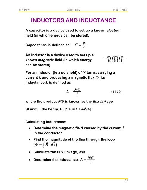
<strong>INDUCTORS</strong> <strong>AND</strong> <strong>INDUCTANCE</strong><br />
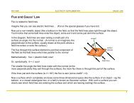
A capacitor is a device used to set up a known electric<br />
field (in which energy can be stored).<br />
Capacitance is defined as<br />
C<br />
=<br />
q<br />
V<br />
An inductor is a device used to set up a<br />
known magnetic field (in which energy<br />
can be stored).<br />
For an inductor (ie a solenoid) of N turns, carrying a<br />
current i, and producing a magnetic flux Φ, its<br />
inductance L is defined as<br />
L<br />
NΦ<br />
i<br />
= (31-30)<br />
where the product NΦ is known as the flux linkage.<br />
SI unit:<br />
the henry, H [1 H = 1 T.m 2 /A]<br />
Calculating inductance:<br />
• Determine the magnetic field caused by the current i<br />
in the conductor<br />
• Find the magnitude of the flux through the loop<br />
<br />
( Φ= B⋅dA)<br />
∫<br />
• Calculate the flux linkage, NΦ<br />
• Determine the inductance,<br />
L =<br />
NΦ<br />
i<br />
30
PHY110W MAGNETISM <strong>INDUCTANCE</strong><br />
<strong>INDUCTANCE</strong> OF A SOLENOID<br />
l<br />
B <br />
For a long solenoid of cross-sectional area A, with n<br />
turns per metre, the magnetic field near its centre is<br />
given by<br />
B<br />
=<br />
µ ni<br />
0<br />
and the flux linkage for this section of the solenoid is<br />
NΦ = ( nl )( BA)<br />
Hence the inductance per unit length of a solenoid is<br />
L<br />
l<br />
2<br />
=<br />
NΦ<br />
= µ 0nA<br />
(31-33)<br />
il<br />
Note that, just as for capacitance, inductance depends<br />
only on the geometry of the device.<br />
31
PHY110W MAGNETISM <strong>INDUCTANCE</strong><br />
SELF-INDUCTION<br />
Changing current in a coil produces a changing<br />
magnetic flux (which induces an emf) …<br />
… not only in another nearby coil, but also in itself!<br />
From Faraday's law, this self-induced emf, E L , is<br />
( Φ)<br />
d N<br />
dt<br />
E L =−<br />
(31-36)<br />
where NΦ = Li (31-35)<br />
di<br />
∴ E L =−L (31-37)<br />
dt<br />
Note that the magnitude of the induced emf does not<br />
depend on the current strength through the coil – but<br />
the rate at which the current is changing.<br />
As usual, the direction of the induced emf is given by<br />
Lenz's law.<br />
32
PHY110W MAGNETISM <strong>INDUCTANCE</strong><br />
RL CIRCUITS<br />
Initially, an inductor acts to oppose changes in the<br />
current through it. A long time later, it acts like<br />
ordinary conducting wire.<br />
Applying Kirchhoff's loop rule to<br />
the adjacent circuit as the<br />
constant emf E is switched on …<br />
E<br />
increasing i<br />
R<br />
L<br />
E L<br />
E<br />
− iR − L di = dt<br />
0<br />
solving which for i we get<br />
i<br />
⎛<br />
=<br />
E<br />
1 −<br />
R<br />
⎜<br />
⎝<br />
e<br />
−Rt L<br />
⎞<br />
⎟<br />
⎠<br />
(31-42)<br />
which can be written as<br />
i<br />
⎛<br />
=<br />
E<br />
−<br />
R ⎜<br />
⎝<br />
−t<br />
τ<br />
L<br />
1 e<br />
⎞<br />
⎟<br />
⎠<br />
(31-43)<br />
where τ L is the inductive time constant (τ L = L / R )<br />
At time t = 0, i = 0. But as t → ∞, i → E / R .<br />
−1<br />
At time t = τ L i =<br />
E<br />
( 1− e ) = 0,63<br />
E .<br />
R<br />
R<br />
Graphically:<br />
i<br />
E<br />
/ R<br />
0.63 E / R<br />
τ L<br />
t<br />
33
PHY110W MAGNETISM <strong>INDUCTANCE</strong><br />
RL CIRCUITS contd<br />
When the battery is switched out of<br />
the circuit, the inductor opposes<br />
the subsequent reduction in<br />
current by developing an emf in the<br />
direction of the original current (i 0 ).<br />
Current decays according to<br />
decreasing i<br />
R<br />
L<br />
E L<br />
E<br />
R<br />
−t<br />
τ<br />
L<br />
i = e = i e<br />
0<br />
−t<br />
τ<br />
L<br />
(31-47)<br />
At time t = 0, i 0 = E / R . But as t → ∞, i → 0.<br />
−1<br />
At time t = τ L i =<br />
E<br />
e = 0,37<br />
E .<br />
R R<br />
Graphically:<br />
i<br />
E<br />
/ R<br />
0.37 E / R<br />
τ L<br />
t<br />
When the current in the circuit is decreasing, the<br />
inductive time constant is the time it takes the current<br />
in the circuit to fall to 37% of its original value.<br />
When the current in the circuit is increasing, the<br />
inductive time constant is the time it takes the current<br />
in the circuit to reach 63% of its peak value.<br />
34
PHY110W MAGNETISM <strong>INDUCTANCE</strong><br />
ENERGY STORED IN<br />
A MAGNETIC FIELD<br />
Just as a capacitor stores energy in its internal electric<br />
field, according to:<br />
U<br />
E<br />
2<br />
1 q<br />
= or<br />
2 C<br />
UE<br />
=<br />
1 CV 2<br />
2<br />
… so an inductor stores energy in its magnetic field.<br />
If the inductor has zero resistance, the potential<br />
difference across it is V = –E.<br />
At any time, the power supplied to the device is<br />
P = Vi = − E i = Li di<br />
dt<br />
and the increase in energy supplied during a time<br />
interval dt is<br />
dU B = P dt = Li di<br />
(31-50)<br />
The total energy required to increase the current from<br />
zero to i is thus<br />
B<br />
i<br />
1 2<br />
∫ (31-51)<br />
2<br />
0<br />
U = L idi = Li<br />
35
PHY110W MAGNETISM <strong>INDUCTANCE</strong><br />
ENERGY DENSITY OF<br />
A MAGNETIC FIELD<br />
In the same way as for the electric field, we can<br />
represent stored magnetic potential energy in terms of<br />
the energy density (ie the energy per unit volume) of<br />
the field.<br />
If, for example the inductor is a long solenoid, of length<br />
d, cross-sectional area A, and n turns per unit length,<br />
the flux is<br />
Φ B = BA = µ 0 niA<br />
The inductance of the solenoid is then<br />
L<br />
=<br />
NΦ<br />
=<br />
i<br />
0<br />
2<br />
µ n lA<br />
from which the stored energy is<br />
2 2<br />
1 2 µ 0ni<br />
UB<br />
= Li = lA<br />
2 2<br />
Recognising that lA is the volume of the magnetic field,<br />
and substituting for the field strength, (B = µ 0 ni) the<br />
energy density per unit volume, u, is<br />
u<br />
B<br />
2 2<br />
µ<br />
2<br />
0ni<br />
= = 1 B<br />
(31-56)<br />
2 2 µ 0<br />
(cf<br />
uE<br />
2<br />
= 1 ε 2<br />
0E<br />
)<br />
36
PHY110W MAGNETISM <strong>INDUCTANCE</strong><br />
MUTUAL INDUCTION<br />
To distinguish it from self-induction, the induction of an<br />
emf in another nearby coil (caused by changing current<br />
– and hence changing magnetic flux) in a coil is better<br />
referred to as mutual induction.<br />
The mutual inductance M 21 of coil 2 with respect to<br />
coil 1 is given by<br />
M<br />
21<br />
N<br />
Φ<br />
2 21<br />
= (31-62)<br />
i1<br />
and hence the emf induced in coil 2 due to the<br />
changing current in coil 1 is<br />
di<br />
=−M dt<br />
1<br />
E 2 21<br />
(31-63)<br />
Similarly,<br />
di<br />
=−M dt<br />
2<br />
E 1 12<br />
(31-64)<br />
where<br />
M<br />
12<br />
=<br />
N Φ<br />
i<br />
1 12<br />
2<br />
But actually M 12 = M 21 = M (31-65)<br />
SI unit:<br />
(as for self-induction)<br />
the henry, H [1 H = 1 T.m 2 /A]<br />
37