MasteringPhysics: Print View with Answers
MasteringPhysics: Print View with Answers
MasteringPhysics: Print View with Answers

You also want an ePaper? Increase the reach of your titles
YUMPU automatically turns print PDFs into web optimized ePapers that Google loves.
Signed in as Jolie Cizewski , Instructor Help Sign Out<br />
RUPHYS2272013 ( RUPHYS2272013 )<br />
My Courses Course Settings<br />
Course Home Assignments Roster Gradebook Item Library<br />
University Physics <strong>with</strong> Modern Physics, 13e<br />
Young/Freedman<br />
Instructor Resources eText Study Area<br />
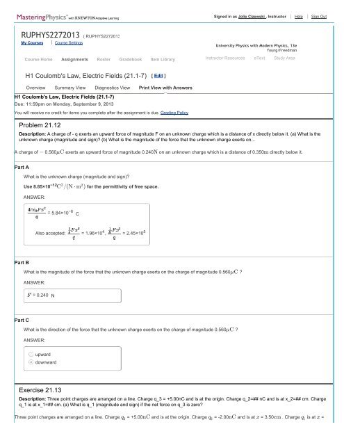
H1 Coulomb's Law, Electric Fields (21.1-7) [ Edit ]<br />
Overview Summary <strong>View</strong> Diagnostics <strong>View</strong> <strong>Print</strong> <strong>View</strong> <strong>with</strong> <strong>Answers</strong><br />
H1 Coulomb's Law, Electric Fields (21.1-7)<br />
Due: 11:59pm on Monday, September 9, 2013<br />
You will receive no credit for items you complete after the assignment is due. Grading Policy<br />
Problem 21.12<br />
Description: A charge of - q exerts an upward force of magnitude F on an unknown charge which is a distance of x directly below it. (a) What is the<br />
unknown charge (magnitude and sign)? (b) What is the magnitude of the force that the unknown charge exerts on...<br />
A charge of − 0.560 µC exerts an upward force of magnitude 0.240 N on an unknown charge which is a distance of 0.350 m directly below it.<br />
Part A<br />
What is the unknown charge (magnitude and sign)?<br />
Use 8.85×10 −12 C 2 /(N ⋅ m 2 ) for the permittivity of free space.<br />
ANSWER:<br />
= 5.84×10 −6 C<br />
Also accepted: = 1.96×10 4 , = 2.45×10 5 µC<br />
Part B<br />
What is the magnitude of the force that the unknown charge exerts on the charge of magnitude 0.560 ?<br />
ANSWER:<br />
= 0.240 N<br />
Part C<br />
What is the direction of the force that the unknown charge exerts on the charge of magnitude 0.560 µC ?<br />
ANSWER:<br />
upward<br />
downward<br />
Exercise 21.13<br />
Description: Three point charges are arranged on a line. Charge q_3 = +5.00nC and is at the origin. Charge q_2=## nC and is at x_2=## cm. Charge<br />
q_1 is at x_1=## cm. (a) What is q_1 (magnitude and sign) if the net force on q_3 is zero?<br />
Three point charges are arranged on a line. Charge q 3 = +5.00 nC and is at the origin. Charge q 2 = -2.00 nC and is at x = 3.50 cm . Charge q 1 is at x =
2.50 cm .<br />
Part A<br />
What is q 1 (magnitude and sign) if the net force on q 3 is zero?<br />
ANSWER:<br />
q = = 1.02<br />
1<br />
nC<br />
Exercise 21.14<br />
Description: Point charge q_1 is located at x = 0, y = 0.30 m, point charge q_2 is located at x = 0 y = -0.30 m. What are (a)the magnitude and<br />
(b)direction of the total electric force that these charges exert on a third point charge Q=## mu C at x = 0.40 m, y = 0? ...<br />
Point charge 1.5 µC is located at x = 0, y = 0.30 m , point charge -1.5 µC is located at x = 0 y = -0.30 m. What are (a)the magnitude and (b)direction of the<br />
total electric force that these charges exert on a third point charge Q = 4.0 µC at x = 0.40 m, y = 0?<br />
Part A<br />
Express your answer using two significant figures.<br />
ANSWER:<br />
|F| = = 0.26<br />
N<br />
Part B<br />
ANSWER:<br />
θ = 90.0 ∘ clockwise from the +x direction<br />
Exercise 21.23<br />
Description: Four identical charges Q are placed at the corners of a square of side L. (a) Find the magnitude total force exerted on one charge by the<br />
other three charges.<br />
Four identical charges Q are placed at the corners of a square of side L.<br />
Part A<br />
Find the magnitude total force exerted on one charge by the other three charges.<br />
Express your answer in terms of the variables Q, L and appropriate constants.<br />
ANSWER:<br />
∣ F⃗ ∣ =<br />
Also accepted: ,<br />
Mystery Charge<br />
Description: Calculate an unknown charge from known charges and forces derived from Coulomb's law<br />
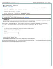
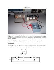
Consider the following configuration of fixed, uniformly charged spheres (see figure):
a blue sphere fixed at the origin <strong>with</strong> positive charge q.<br />
a red sphere fixed at the point ( d 1 , 0) <strong>with</strong> unknown charge q red ,<br />
a yellow sphere fixed at the point ( d 2 cos(θ), −d 2 sin(θ)) <strong>with</strong> unknown charge q yellow .<br />
The net electric force on the blue sphere is observed to be F ⃗ = (0, −F) , where F > 0.<br />
Part A<br />
What is the sign of the charge on the yellow sphere?<br />
ANSWER:<br />
positive<br />
negative<br />
Part B<br />
What is the sign of the charge on the red sphere?<br />
ANSWER:<br />
positive<br />
negative<br />
Part C<br />
Suppose that the magnitude of the charge on the yellow sphere is determined to be 2q. Calculate the charge q red on the red sphere.<br />
Express your answer in terms of q, d 1 , d 2 , and θ.<br />
Hint 1. How to approach the problem<br />
From the problem statement, you know that the x component of the net force acting on the blue sphere must vanish. The red sphere and the<br />
yellow sphere each exert a force on the blue sphere. You know the charge of the yellow sphere. This allows you to calculate the x component of<br />
the force that the yellow sphere exerts on the blue sphere. You need to find the appropriate charge q red for the red sphere such that the x<br />
components of the two forces sum to zero.<br />
Hint 2. Find the force due to the yellow sphere<br />
Find<br />
F x.yellow the x component of the force that the yellow sphere exerts on the blue sphere.<br />
q d 2 θ k 1<br />
Express your answer in terms of , , and . You may use for , where ϵ represents the permittivity of free space.<br />
4πϵ 0<br />
0<br />
Hint 1. How to approach this part<br />
Use Coulomb's Law to find the force due to the yellow charge on the blue charge. Then resolve this force into components.
Note that Coulomb's Law gives the total force between charges. To find a component, you must first apply Coulomb's Law to find the total<br />
force and then resolve the force. It is incorrect to first resolve the relative position vector and then use Coulomb's Law separately for each<br />
component.<br />
ANSWER:<br />
F x.yellow =<br />
Also accepted:<br />
Hint 3. Find the force due to the red sphere<br />
Find<br />
F x.red , the x component of the force that the red sphere exerts on the blue sphere.<br />
q d 1 q red k 1<br />
Express your answer in terms of , , and the unknown charge . You may use for , where ϵ represents the permittivity of<br />
4πϵ 0<br />
0<br />
free space.<br />
ANSWER:<br />
F x.red =<br />
Also accepted:<br />
ANSWER:<br />
q red =<br />
Visualizing Electric Fields<br />
Description: Select the correct drawing of electric field lines for several situations and answer questions about why other choices are incorrect. Then,<br />
these ideas are demonstrated <strong>with</strong> an applet.<br />
Learning Goal:<br />
To understand the nature of electric fields and how to draw field lines.<br />
Electric field lines are a tool used to visualize electric fields. A field line is drawn beginning at a positive charge and ending at a negative charge. Field lines<br />
may also appear from the edge of a picture or disappear at the edge of the picture. Such lines are said to begin or end at infinity. The field lines are directed<br />
so that the electric field at any point is tangent to the field line at that point.<br />
The figure shows two different ways to visualize an electric field. On the left, vectors are drawn at various points to show the direction and magnitude of the<br />
electric field. On the right, electric field lines depict the same situation. Notice that, as stated above, the electric field lines are drawn such that their tangents<br />
point in the same direction as the electric field vectors on the left. Because of the nature of electric fields, field lines never cross. Also, the vectors shrink as<br />
you move away from the charge, and the electric field lines spread out as you move away from the charge. The spacing between electric field lines<br />
indicates the strength of the electric field, just as the length of vectors indicates the strength of the electric field. The greater the spacing between field lines,<br />
the weaker the electric field. Although the advantage of field lines over field vectors may not be apparent in the case of a single charge, electric field lines<br />
present a much less cluttered and more intuitive picture of more complicated charge arrangements.
Part A<br />
Which of the following figures correctly depicts the field lines from an infinite uniformly<br />
negatively charged sheet? Note that the sheet is being viewed edge-on in all pictures.<br />
Hint 1. Description of the field<br />
Recall that the field around an infinite charged sheet is always perpendicular to the sheet and that the field strength does not change, regardless<br />
of distance from the sheet.<br />
ANSWER:<br />
A<br />
B<br />
C<br />
D<br />
Part B<br />
In the diagram from part A , what is wrong <strong>with</strong> figure B? (Pick only those statements that<br />
apply to figure B.)<br />
Check all that apply.<br />
ANSWER:
Field lines cannot cross each other.<br />
The field lines should be parallel because of the sheet's symmetry.<br />
The field lines should spread apart as they leave the sheet to indicate the weakening of the field <strong>with</strong> distance.<br />
The field lines should always end on negative charges or at infinity.<br />
Part C<br />
Which of the following figures shows the correct electric field lines for an electric dipole?<br />
ANSWER:<br />
A<br />
B<br />
C<br />
D<br />
This applet shows two charges. You can alter the charge on each independently or alter the distance between them. You should try to get a<br />
feeling for how altering the charges or the distance affects the field lines.<br />
Part D<br />
In the diagram from part C , what is wrong <strong>with</strong> figure D? (Pick only those statements that<br />
apply to figure D.)<br />
Check all that apply.<br />
ANSWER:<br />
Field lines cannot cross each other.<br />
The field lines should turn sharply as you move from one charge to the other.<br />
The field lines should be smooth curves.<br />
The field lines should always end on negative charges or at infinity.
In even relatively simple setups as in the figure, electric field lines are quite helpful for<br />
understanding the field qualitatively (understanding the general direction in which a certain charge will move from a specific position, identifying<br />
locations where the field is roughly zero or where the field points a specific direction, etc.). A good figure <strong>with</strong> electric field lines can help you to<br />
organize your thoughts as well as check your calculations to see whether they make sense.<br />
Part E<br />
In the figure , the electric field lines are shown for a system of two point charges, Q A and Q B . Which of the following could represent the magnitudes<br />
and signs of Q A and Q B ?<br />
In the following, take q to be a positive quantity.<br />
ANSWER:<br />
Q A = +q,<br />
Q B = −q<br />
Q A = +7q,<br />
Q B = −3q<br />
Q A = +3q,<br />
Q B = −7q<br />
Q A = −3q,<br />
Q B = +7q<br />
Q A = −7q,<br />
Q B = +3q<br />
+ = +4q<br />
Very far from the two charges, the system looks like a single charge <strong>with</strong> value Q A<br />
be indistinguishable from the field lines due to a single point charge +4q.<br />
Q B<br />
. At large enough distances, the field lines will<br />
Exercise 21.39<br />
Description: A point charge is at the origin. With this point charge as the source point, what is the unit vector r_unit in the direction of (a) the field point<br />
at x = 0 , y = -1.35m; (b) the field point at x = 12.0cm, y = 12.0cm; (c) the field point at x = -...<br />
A point charge is at the origin. With this point charge as the source point, what is the unit vector r^ in the direction of (a) the field point at x = 0 , y = -1.35 m;<br />
(b) the field point at x = 12.0 cm, y = 12.0 cm; (c) the field point at x = - 1.10 m, y = 2.60 m? Express your results in terms of the unit vectors i^ and j^ .<br />
Part A<br />
Express your answer in terms of the unit vectors i^ and j^ .
ANSWER:<br />
r^ =<br />
Part B<br />
Express your answer in terms of the unit vectors i^ and j^ .<br />
ANSWER:<br />
r^ =<br />
Part C<br />
Express your answer in terms of the unit vectors i^ and j^ .<br />
ANSWER:<br />
r^ =<br />
Exercise 21.59<br />
Description: An electric dipole <strong>with</strong> dipole moment p_vec is in a uniform electric field E_vec. (a) Find all the orientations of the dipole for which the<br />
torque on the dipole is zero. (b) Which of the orientations in part (a) is stable, and which is unstable?...<br />
An electric dipole <strong>with</strong> dipole moment p⃗ is in a uniform electric field E ⃗ .<br />
Part A<br />
Find all the orientations of the dipole for which the torque on the dipole is zero.<br />
Enter your answers numerically separated by a commas.<br />
ANSWER:<br />
θ = ∘<br />
0, 180 counterclockwise from the electric field direction<br />
Also accepted: 180, 0<br />
Part B<br />
Which of the orientations in part (a) is stable, and which is unstable? (Hint: Consider a small displacement away from the equilibrium position and see<br />
what happens.)<br />
ANSWER:<br />
stable orientation is only when p⃗ is aligned in the same direction as E ⃗<br />
stable orientation is only when p⃗ is aligned in the opposite direction of E ⃗<br />
stable orientations are only when p⃗ is aligned in the opposite or the same direction as E ⃗<br />
Copyright © 2013 Pearson. All rights reserved.<br />
Legal Notice Privacy Policy Permissions Support


![More Effective C++ [Meyers96]](https://img.yumpu.com/25323611/1/184x260/more-effective-c-meyers96.jpg?quality=85)