
Create successful ePaper yourself
Turn your PDF publications into a flip-book with our unique Google optimized e-Paper software.
i,cllipr-:;,*r' :i*ri:c,r iJ{:**-:1,..!,:;n, *r;11r,:rlrl.;rnd :r*t-vl':e 605<br />
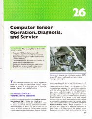
Ford Throtlle Posilion (TP) Sensor <strong>Ch</strong>art<br />
Throttle Angle (Degrees)<br />
Voltage (V)<br />
0 0.50<br />
10 0.97<br />
20<br />
1 lA<br />
30 1.90<br />
40 2.37<br />
50 2.84<br />
60 .t.J I<br />
70 3.78<br />
BO 4.24<br />
Testing the Tlerm'&tfre<br />
Fosition Semser<br />
A TP sensor can be tested using one or more of the<br />
following tools:<br />
x A digital voltmeter with three test leads connected<br />
in series between the sensor and the wiring<br />
harness connector or backprobing using T-pins.<br />
€ A scan tool or a specific tool recommended by the<br />
vehicle manufacturer.<br />
tr Abreakout box that is connected in series<br />
between the computer and the wiring harness<br />
connector(s). A typical breakout box includes test<br />
points at which TP voltages can be measured<br />
with a digital voltmeter.<br />
ffi An oscilloscope.<br />
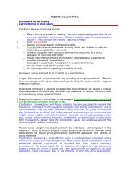
i::!;41ii:re* ?**E E A meter lead connected to a T-pin that<br />
was gently pushed along the signal wire of the TP sensor<br />
until the point of the pin touched the metal terminal inside<br />
the olastic connector.<br />
A 1V nC I :1 PRS8E B 2S0mV tlFF 1 r l PRilBE<br />
200msrBIV $IN&LE f.igrAJ -3nIU<br />
Use jumper wires, T-pins, or a breakout box to<br />
gain electrical access to the wiring to the TP sensor.<br />
See Figure <strong>26</strong>-17.<br />
r. r , lrlr irii'ltt*.ci:xilj:!\i:UIiqiirS{n4fillii{ilisFt$rli$lirui{ii$ill$i{lritiiil]riiliirlirlt{rilliqj*l<br />
The procedure that follows is the usual 1<br />
method ,rsed by many manufacturers. Always refer to I<br />
serrice literature for the exact tecommended procedure I<br />
, .and specifications for the vehicle bein9 fested,<br />
I<br />
The procedure fol testing the sensor using a digital<br />
multimeter is as follos's:<br />
I". Turn the ignition ss'itch on rengine offl.<br />
2. Measure the voltage benr-een the signai wire<br />
and ground (reference ios- s-ire. The r-oltage<br />
should be about 0.5 volt.<br />
' Consult the service literature for exact rvire<br />
colors or locations.<br />
3. \\-ith the engine still not running (but ivith the<br />
igmtion sti11 on ), slowly increase the thlottle<br />
FREE I*PTURE l,lil{ ltlAH<br />
EUH 10 milIV on A<br />
TRIGGER<br />
at 5t3X<br />
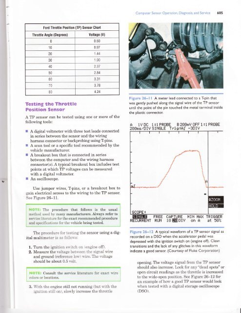
Fig:irre ?#"*i? A typical waveform of a TP sensor signal as<br />
recorded on a DSO when the accelerator pedal was<br />
depressed with the ignition switch on (engine off). Clean<br />
transitions and the lacl< of any glitches in this waveform<br />
indicate a good sensor. (Courtesy of Fluke Corporation)<br />
opening. The voltage signal from the TP sensor<br />
should also increase. Look for any "dead spots" or<br />
open circuit readings as the throttle is increased<br />
to the wide-open position. See Figure <strong>26</strong>-12 for<br />
an example of how a good TP sensor would look<br />
u'hen tested rvith a digital storage oscilloscope<br />
(DSO).