
You also want an ePaper? Increase the reach of your titles
YUMPU automatically turns print PDFs into web optimized ePapers that Google loves.
Canrputer Sensor Operation, Diagnosis, and Service 603<br />
HARNESS<br />
CONNECTOR<br />
a @-@@<br />
!B{j6Fe<br />
JUMPER WIRES<br />
Tr\<br />
VACUUM<br />
PUMP<br />
9*99:<br />
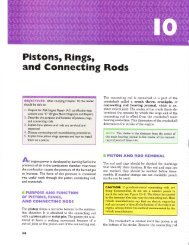
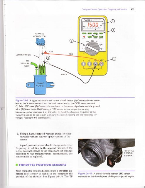
Figure <strong>26</strong>-q A digital multimeter set to test a MAP sensor. (l) Connect the red meter<br />
lead to the V meter terminal and the black meter lead to the COM meter terminal.<br />
(2) Select DC volts. (3) Connect rhe rest leads to the sensor signal wire and the ground<br />
wire. (4) Select hertz (Hz) if testing a MAP sensor whose output is a varying<br />
frequency-otherwise keep it on DC vohs. (5) Read the change of frequency as the<br />
vacuum is applied to the sensor. Compare the vacuum reading and the frequency (or<br />
voltage) reading to the specifications.<br />
3. Using a hand-operated vacuum pump (or other<br />
variable vacuum source), apply vacuum to the<br />
sensor<br />
A good pressure sensor should change voltage t or<br />
frequency) in relation to the applied vacuum. If the<br />
signal does not change or the values are out ofrange<br />
according to the manufacturers' specifications, the<br />
sensor must be replaced.<br />
F THROTTIE POSITION $EHSORS<br />
Most computer-equipped engines use a throttle position<br />
(TP) sensor to signal to the computer the<br />
position of the throttle. See Figure <strong>26</strong>-10. The TP<br />
Figure <strong>26</strong>*lS A typicalthrottle position (TP) sensor<br />
mounted on the throttle plate of this port-injected engine.