
Create successful ePaper yourself
Turn your PDF publications into a flip-book with our unique Google optimized e-Paper software.
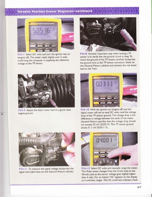
?24-7 Select DC volts and turn the ignition key on<br />
(engine off). The meter reads slightly over 5 volts,<br />
confirming the computer is supplying the reference<br />
voltage to the TP sensor.<br />
P24-8 Another important step when testing a TP<br />
sensor is to verify that the ground circuit is okay' To<br />
check the ground of the TP sensor, carefully baclcprobe<br />
the ground wire at the TP sensor connector (black on<br />
this General Motors vehicle) and connect the red meter<br />
lead to the T-pin.<br />
F?4*9 Attach the black meter lead to a good, clean<br />
engine grouncl.<br />
P24-10 With the ignition on (engine ofl) and the<br />
digital meter still set to read DC volts' read the voltage<br />
drop of the TP sensor ground. The voltage drop is the<br />
difference in voltage between the leads of the meter.<br />
General Motors specifies that this voltage drop should<br />
not exceed 35 mV (0.035 V). This TP sensor ground<br />
shows 3l.l mV (0.03 I I V).<br />
PZ4-l I To measure the signal voltage, backprobe the<br />
signal wire (dark blue on this General Motors vehicle).<br />
.-s<br />
P24-12 Select DC volts and manually range the meter'<br />
This Fluke meter changes from the 4-volt scale to the<br />
4O-volt scale as the sensor voltage goes slightly higher<br />
than 4 volts. For an instant,"OU' aPPears on the display<br />
as it switches ranges. This OL could also indicate a fault.<br />
617