MDH-302/402 & Icepic / Selectable Ice Series - Manitowoc ...
MDH-302/402 & Icepic / Selectable Ice Series - Manitowoc ...
MDH-302/402 & Icepic / Selectable Ice Series - Manitowoc ...

You also want an ePaper? Increase the reach of your titles
YUMPU automatically turns print PDFs into web optimized ePapers that Google loves.
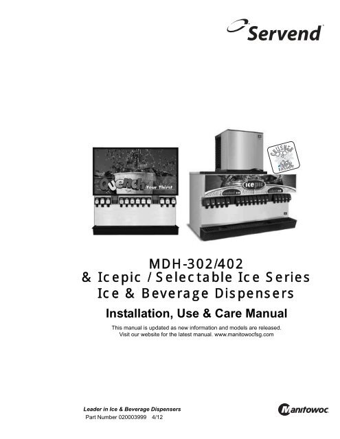
<strong>MDH</strong>-<strong>302</strong>/<strong>402</strong><br />
& <strong><strong>Ice</strong>pic</strong> / <strong>Selectable</strong> <strong>Ice</strong> <strong>Series</strong><br />
<strong>Ice</strong> & Beverage Dispensers<br />
Installation, Use & Care Manual<br />
This manual is updated as new information and models are released.<br />
Visit our website for the latest manual. www.manitowocfsg.com<br />
Leader in <strong>Ice</strong> & Beverage Dispensers<br />
Part Number 020003999 4/12
Safety Notices<br />
As you work on <strong>Manitowoc</strong> equipment, be sure to pay<br />
close attention to the safety notices in this manual.<br />
Disregarding the notices may lead to serious injury and/<br />
or damage to the equipment.<br />
Throughout this manual, you will see the following types<br />
of safety notices:<br />
! Warning<br />
Text in a Warning box alerts you to a potential<br />
personal injury situation. Be sure to read the<br />
Warning statement before proceeding, and work<br />
carefully.<br />
! Caution<br />
Text in a Caution box alerts you to a situation in<br />
which you could damage the equipment. Be sure to<br />
read the Caution statement before proceeding, and<br />
work carefully.<br />
Procedural Notices<br />
As you work on <strong>Manitowoc</strong> equipment, be sure to read<br />
the procedural notices in this manual. These notices<br />
supply helpful information which may assist you as you<br />
work.<br />
Throughout this manual, you will see the following types<br />
of procedural notices:<br />
Important<br />
Text in an Important box provides you with<br />
information that may help you perform a procedure<br />
more efficiently. Disregarding this information will<br />
not cause damage or injury, but it may slow you<br />
down as you work.<br />
NOTE: Text set off as a Note provides you with simple,<br />
but useful, extra information about the procedure you<br />
are performing.<br />
Read These Before Proceeding:<br />
! Caution<br />
Proper installation, care and maintenance are<br />
essential for maximum performance and troublefree<br />
operation of your <strong>Manitowoc</strong> equipment. Read<br />
and understand this manual. It contains valuable<br />
care and maintenance information. If you encounter<br />
problems not covered by this manual, do not<br />
proceed, contact <strong>Manitowoc</strong> Foodservice Group.<br />
We will be happy to provide assistance.<br />
Important<br />
Routine adjustments and maintenance procedures<br />
outlined in this manual are not covered by the<br />
warranty.<br />
! Warning<br />
PERSONAL INJURY POTENTIAL<br />
Do not operate equipment that has been misused,<br />
abused, neglected, damaged, or altered/modified<br />
from that of original manufactured specifications.<br />
NOTE: SAVE THESE INSTRUCTIONS.<br />
We reserve the right to make product improvements at any time.<br />
Specifications and design are subject to change without notice.
Section 1<br />
General Information<br />
Section 2<br />
Installation Instructions<br />
Read This Manual . . . . . . . . . . . . . . . . . . . . . . . . . . . . . . . . . . . . . . . . . . . . . . . . . 1-1<br />
Unit Inspection . . . . . . . . . . . . . . . . . . . . . . . . . . . . . . . . . . . . . . . . . . . . . . . . . . . 1-1<br />
Model Numbers. . . . . . . . . . . . . . . . . . . . . . . . . . . . . . . . . . . . . . . . . . . . . . . . . . . 1-1<br />
How To Read A Model Number . . . . . . . . . . . . . . . . . . . . . . . . . . . . . . . . . 1-1<br />
Accessories. . . . . . . . . . . . . . . . . . . . . . . . . . . . . . . . . . . . . . . . . . . . . . . . . . . . . . 1-1<br />
Baffle for <strong>Manitowoc</strong> ® <strong>Ice</strong> Machine . . . . . . . . . . . . . . . . . . . . . . . . . . . . . . . 1-1<br />
Manual Fill Lid for Dispensers with aN <strong>Ice</strong> Machine . . . . . . . . . . . . . . . . . . 1-1<br />
Legs . . . . . . . . . . . . . . . . . . . . . . . . . . . . . . . . . . . . . . . . . . . . . . . . . . . . . . 1-2<br />
Serial Number Location . . . . . . . . . . . . . . . . . . . . . . . . . . . . . . . . . . . . . . . . . . . . 1-2<br />
General . . . . . . . . . . . . . . . . . . . . . . . . . . . . . . . . . . . . . . . . . . . . . . . . . . . . . . . . . 2-1<br />
Dimensions . . . . . . . . . . . . . . . . . . . . . . . . . . . . . . . . . . . . . . . . . . . . . . . . . . . . . . 2-1<br />
<strong>MDH</strong>-<strong>302</strong> & <strong>402</strong> Footprint. . . . . . . . . . . . . . . . . . . . . . . . . . . . . . . . . . . . . . . . . . . 2-2<br />
Location. . . . . . . . . . . . . . . . . . . . . . . . . . . . . . . . . . . . . . . . . . . . . . . . . . . . . . . . . 2-3<br />
Location Requirements for Top Mounted <strong>Ice</strong> Machine Installations . . . . . . 2-3<br />
Pre-installation Checklist. . . . . . . . . . . . . . . . . . . . . . . . . . . . . . . . . . . . . . . . . . . 2-4<br />
Bulk Syrup System also: . . . . . . . . . . . . . . . . . . . . . . . . . . . . . . . . . . . . . . . 2-4<br />
Double Check: . . . . . . . . . . . . . . . . . . . . . . . . . . . . . . . . . . . . . . . . . . . . . . 2-5<br />
Also Consider The Location Of The Following Items Before Installation: . . 2-5<br />
Additional Checks for Top Mounted <strong>Ice</strong> Machine Installations . . . . . . . . . . 2-5<br />
Assembly. . . . . . . . . . . . . . . . . . . . . . . . . . . . . . . . . . . . . . . . . . . . . . . . . . . . . . . . 2-6<br />
Installing Baffle for <strong>Ice</strong> Machine Installations . . . . . . . . . . . . . . . . . . . . . . . 2-6<br />
“S” <strong>Series</strong> Baffle . . . . . . . . . . . . . . . . . . . . . . . . . . . . . . . . . . . . . . . . . . . . . 2-6<br />
“Q” <strong>Series</strong> Baffle . . . . . . . . . . . . . . . . . . . . . . . . . . . . . . . . . . . . . . . . . . . . . 2-6<br />
Electrical . . . . . . . . . . . . . . . . . . . . . . . . . . . . . . . . . . . . . . . . . . . . . . . . . . . . . . . . 2-7<br />
General . . . . . . . . . . . . . . . . . . . . . . . . . . . . . . . . . . . . . . . . . . . . . . . . . . . . 2-7<br />
Minimum Circuit Ampacity . . . . . . . . . . . . . . . . . . . . . . . . . . . . . . . . . . . . . 2-7<br />
Electrical Requirements . . . . . . . . . . . . . . . . . . . . . . . . . . . . . . . . . . . . . . . 2-7<br />
Voltage . . . . . . . . . . . . . . . . . . . . . . . . . . . . . . . . . . . . . . . . . . . . . . . . . . . . 2-7<br />
Minimum Circuit Amperage Chart . . . . . . . . . . . . . . . . . . . . . . . . . . . . . . . . 2-7<br />
Grounding Instructions . . . . . . . . . . . . . . . . . . . . . . . . . . . . . . . . . . . . . . . . . . . . 2-7<br />
Pump Deck Wiring . . . . . . . . . . . . . . . . . . . . . . . . . . . . . . . . . . . . . . . . . . . 2-8
Section 3<br />
Operation<br />
Water Supply . . . . . . . . . . . . . . . . . . . . . . . . . . . . . . . . . . . . . . . . . . . . . . . . . . . . . 2-9<br />
Recommended Plumbing . . . . . . . . . . . . . . . . . . . . . . . . . . . . . . . . . . . . . . 2-9<br />
Diagram Location . . . . . . . . . . . . . . . . . . . . . . . . . . . . . . . . . . . . . . . . . . . . 2-9<br />
<strong>MDH</strong>-<strong>302</strong> 12 Valve Plumbing DIagram . . . . . . . . . . . . . . . . . . . . . . . . . . . . 2-10<br />
<strong>MDH</strong>-<strong>302</strong> 12 Valve Flex Manifold (1 PER SIDE) . . . . . . . . . . . . . . . . . . . . . 2-10<br />
<strong>MDH</strong>-<strong>402</strong> 16 Valve Plumbing DIagramS . . . . . . . . . . . . . . . . . . . . . . . . . . . 2-11<br />
<strong>MDH</strong>-<strong>402</strong> 16 Valve Flex Manifold (1 PER SIDE) . . . . . . . . . . . . . . . . . . . . . 2-11<br />
<strong>MDH</strong>-<strong>402</strong> 20 Valve Plumbing DIagram . . . . . . . . . . . . . . . . . . . . . . . . . . . . 2-12<br />
<strong>MDH</strong>-<strong>402</strong> 20 Valve Flex Manifold (1 PER SIDE) . . . . . . . . . . . . . . . . . . . . . 2-12<br />
CO2 System . . . . . . . . . . . . . . . . . . . . . . . . . . . . . . . . . . . . . . . . . . . . . . . . . . . . . . 2-13<br />
Routing Internal Carb Tank Purge Tube . . . . . . . . . . . . . . . . . . . . . . . . . . . 2-13<br />
Drains . . . . . . . . . . . . . . . . . . . . . . . . . . . . . . . . . . . . . . . . . . . . . . . . . . . . . 2-13<br />
Step by Step Installation. . . . . . . . . . . . . . . . . . . . . . . . . . . . . . . . . . . . . . . . . . . . 2-14<br />
General . . . . . . . . . . . . . . . . . . . . . . . . . . . . . . . . . . . . . . . . . . . . . . . . . . . . 2-14<br />
Capacities . . . . . . . . . . . . . . . . . . . . . . . . . . . . . . . . . . . . . . . . . . . . . . . . . . 2-14<br />
Specifications Chart . . . . . . . . . . . . . . . . . . . . . . . . . . . . . . . . . . . . . . . . . . . 2-14<br />
Unit Installation . . . . . . . . . . . . . . . . . . . . . . . . . . . . . . . . . . . . . . . . . . . . . . 2-14<br />
System Pressures . . . . . . . . . . . . . . . . . . . . . . . . . . . . . . . . . . . . . . . . . . . . 2-14<br />
ADA Key Pads . . . . . . . . . . . . . . . . . . . . . . . . . . . . . . . . . . . . . . . . . . . . . . . 2-15<br />
Starting Your Beverage System & Dispenser . . . . . . . . . . . . . . . . . . . . . . . 2-16<br />
General System Overview . . . . . . . . . . . . . . . . . . . . . . . . . . . . . . . . . . . . . . . . . . 3-1<br />
<strong>MDH</strong>-<strong>302</strong> Cold Carbonation System . . . . . . . . . . . . . . . . . . . . . . . . . . . . . . . . . . 3-2<br />
For Serials Prior to 610115880 . . . . . . . . . . . . . . . . . . . . . . . . . . . . . . . . . . 3-2<br />
For Serials 610115880 & up . . . . . . . . . . . . . . . . . . . . . . . . . . . . . . . . . . . . 3-3<br />
<strong>MDH</strong>-<strong>402</strong> Cold Carbonation System . . . . . . . . . . . . . . . . . . . . . . . . . . . . . . . . . . 3-4<br />
Component Identification . . . . . . . . . . . . . . . . . . . . . . . . . . . . . . . . . . . . . . . . . . . 3-5<br />
Sequence of Operation . . . . . . . . . . . . . . . . . . . . . . . . . . . . . . . . . . . . . . . . . . . . . 3-5<br />
<strong>Ice</strong> Recommended for Dispensing . . . . . . . . . . . . . . . . . . . . . . . . . . . . . . . 3-5<br />
Non-Adjustable Agitation Timer . . . . . . . . . . . . . . . . . . . . . . . . . . . . . . . . . . 3-5<br />
<strong>Ice</strong> Storage and Dispensing . . . . . . . . . . . . . . . . . . . . . . . . . . . . . . . . . . . . 3-6<br />
Carbonation . . . . . . . . . . . . . . . . . . . . . . . . . . . . . . . . . . . . . . . . . . . . . . . . . 3-6<br />
Syrup Delivery System . . . . . . . . . . . . . . . . . . . . . . . . . . . . . . . . . . . . . . . . . . . . . 3-7<br />
B-I-B . . . . . . . . . . . . . . . . . . . . . . . . . . . . . . . . . . . . . . . . . . . . . . . . . . . . . . 3-8<br />
Figal System . . . . . . . . . . . . . . . . . . . . . . . . . . . . . . . . . . . . . . . . . . . . . . . . 3-8<br />
Operation Checks & Adjustments . . . . . . . . . . . . . . . . . . . . . . . . . . . . . . . . . . . . 3-9<br />
<strong>Ice</strong> Delivery Switch Adjustment . . . . . . . . . . . . . . . . . . . . . . . . . . . . . . . . . . 3-9<br />
Crushed or Cubed Default . . . . . . . . . . . . . . . . . . . . . . . . . . . . . . . . . . . . . . 3-9<br />
agitation timer operational check . . . . . . . . . . . . . . . . . . . . . . . . . . . . . . . . . 3-9
Section 4<br />
Maintenance<br />
Section 5<br />
Before Calling for Service<br />
Cleaning. . . . . . . . . . . . . . . . . . . . . . . . . . . . . . . . . . . . . . . . . . . . . . . . . . . . . . . . . 4-1<br />
Daily Cleaning . . . . . . . . . . . . . . . . . . . . . . . . . . . . . . . . . . . . . . . . . . . . . . . 4-1<br />
Monthly Cleaning . . . . . . . . . . . . . . . . . . . . . . . . . . . . . . . . . . . . . . . . . . . . 4-2<br />
Cleaning Checklist . . . . . . . . . . . . . . . . . . . . . . . . . . . . . . . . . . . . . . . . . . . 4-2<br />
Preventive Maintenance. . . . . . . . . . . . . . . . . . . . . . . . . . . . . . . . . . . . . . . . . . . . 4-3<br />
Disassembly . . . . . . . . . . . . . . . . . . . . . . . . . . . . . . . . . . . . . . . . . . . . . . . . . . . . . 4-3<br />
Disassembly for Cleaning and Maintenance . . . . . . . . . . . . . . . . . . . . . . . . 4-3<br />
Disassemble the Rocking Chute . . . . . . . . . . . . . . . . . . . . . . . . . . . . . . . . . 4-4<br />
Disassemble the <strong>Ice</strong> Crusher Assembly . . . . . . . . . . . . . . . . . . . . . . . . . . . 4-4<br />
Monthly <strong>Ice</strong> Crusher Assembly Cleaning . . . . . . . . . . . . . . . . . . . . . . . . . . 4-6<br />
reassemble the <strong>Ice</strong> Crusher assembly . . . . . . . . . . . . . . . . . . . . . . . . . . . . 4-7<br />
Gear Motor Removal . . . . . . . . . . . . . . . . . . . . . . . . . . . . . . . . . . . . . . . . . . 4-8<br />
Sanitizing. . . . . . . . . . . . . . . . . . . . . . . . . . . . . . . . . . . . . . . . . . . . . . . . . . . . . . . . 4-10<br />
Beverage System Cleaning . . . . . . . . . . . . . . . . . . . . . . . . . . . . . . . . . . . . 4-10<br />
Bag-In-Box System Sanitation . . . . . . . . . . . . . . . . . . . . . . . . . . . . . . . . . . 4-10<br />
Figal Beverage System . . . . . . . . . . . . . . . . . . . . . . . . . . . . . . . . . . . . . . . . 4-11<br />
Shipping, Storage and Relocation . . . . . . . . . . . . . . . . . . . . . . . . . . . . . . . . . . . 4-11<br />
<strong>MDH</strong> <strong>Series</strong> Graphic Medallion Removal & Installation . . . . . . . . . . . . . . . . . . 4-12<br />
Medallion Removal . . . . . . . . . . . . . . . . . . . . . . . . . . . . . . . . . . . . . . . . . . . 4-12<br />
Checklist . . . . . . . . . . . . . . . . . . . . . . . . . . . . . . . . . . . . . . . . . . . . . . . . . . . . . . . . 5-1<br />
<strong><strong>Ice</strong>pic</strong> Troubleshooting . . . . . . . . . . . . . . . . . . . . . . . . . . . . . . . . . . . . . . . . . . . . 5-2<br />
Pump Troubleshooting. . . . . . . . . . . . . . . . . . . . . . . . . . . . . . . . . . . . . . . . . . . . . 5-2<br />
<strong>Selectable</strong> <strong>Ice</strong> Troubleshooting. . . . . . . . . . . . . . . . . . . . . . . . . . . . . . . . . . . . . . 5-3<br />
Drink Troubleshooting . . . . . . . . . . . . . . . . . . . . . . . . . . . . . . . . . . . . . . . . . . . . . 5-4<br />
Liquid Level Control Troubleshooting . . . . . . . . . . . . . . . . . . . . . . . . . . . . . . . . 5-5
Table of Contents<br />
Part Number 020003999 4/12 4
Section 1 General Information<br />
Read This Manual<br />
<strong>Manitowoc</strong> Beverage Equipment (MBE) developed this<br />
manual as a reference guide for the owner/operator and<br />
installer of this equipment. Please read this manual<br />
before installation or operation of the machine. A<br />
qualified service technician must perform installation and<br />
start-up of this equipment, consult Section 5 within this<br />
manual for service assistance.<br />
If you cannot correct the service problem, call your MBE<br />
Service Agent or Distributor. Always have your model<br />
and serial number available when you call.<br />
Your Service Agent ____________________________<br />
Service Agent Telephone Number _________________<br />
Your Local MBE Distributor ______________________<br />
Distributor Telephone Number ____________________<br />
Model Number _______________________________<br />
Serial Number ________________________________<br />
Installation Date ______________________________<br />
Unit Inspection<br />
Thoroughly inspect the unit upon delivery. Immediately<br />
report any damage that occurred during transportation to<br />
the delivery carrier. Request a written inspection report<br />
from a claims inspector to document any necessary<br />
claim.<br />
! Warning<br />
PERSONAL INJURY POTENTIAL<br />
Do not operate equipment that has been misused,<br />
abused, neglected, damaged, or altered/modified<br />
from that of original manufactured specifications.<br />
Section 1<br />
General Information<br />
Model Numbers<br />
This manual covers the following models:<br />
HOW TO READ A MODEL NUMBER<br />
Accessories<br />
Beverage/<strong>Ice</strong> Dispensers<br />
<strong>MDH</strong>-<strong>302</strong>, <strong>MDH</strong>-<strong>402</strong>, <strong>MDH</strong>-<strong>302</strong> CI,<br />
<strong>MDH</strong>-<strong>402</strong> CI, <strong>MDH</strong>-<strong>402</strong> SCI<br />
S = <strong>Ice</strong> Only<br />
SV = <strong>Ice</strong>/Beverage<br />
NGF = <strong>Ice</strong>/Beverage<br />
FRP = <strong>Ice</strong>/Beverage &<br />
Integrated Flavor Shots<br />
Model Base<br />
Model Prefix Model Suffix<br />
<strong>MDH</strong>–<strong>302</strong>–i<br />
<strong>Ice</strong> Capacity<br />
i = Intellicarb<br />
CI = <strong>Ice</strong> Crusher (<strong>Ice</strong>Pic)<br />
SCI = <strong>Selectable</strong><br />
Crushed <strong>Ice</strong><br />
BAFFLE FOR MANITOWOC® ICE MACHINE<br />
When installing a <strong>Manitowoc</strong> <strong>Ice</strong> Machine on a<br />
dispenser, a baffle kit is required for proper installation.<br />
The baffle kit is designed to prevent ice from lying<br />
against the front of the ice machine, and melting down<br />
the front of the dispenser. There are two different baffle<br />
kits available for “S” series ice machines, one kit is for<br />
the 30" wide machine, and the other kit is for the 22"<br />
wide machine. There is also a kit for “Q” series ice<br />
machines.<br />
Kits are available through your local distributor. List<br />
prices may be subject to change without notification.<br />
Please call your local parts distributor for current pricing<br />
before ordering.<br />
MANUAL FILL LID FOR DISPENSERS<br />
WITH AN ICE MACHINE<br />
If you are top mounting your dispenser with a ice<br />
machine, you will require a lid for the manual fill area at<br />
the top, front of the dispenser.<br />
If you ordered a dispenser and a ice machine at the<br />
same time, the manual fill lid was included with the unit.<br />
The manual fill lid can be ordered from your local<br />
distributor.<br />
Part Number 020003999 4/12 1-1
General Information Section 1<br />
LEGS<br />
Legs are optional equipment with most MBE dispensers.<br />
Standard legs are 4" (10.2 cm) tall stainless steel legs. If<br />
an ice machine is installed on top of the dispenser, legs<br />
must not be installed. We do not recommend using legs<br />
when an ice machine is mounted on the dispenser. The<br />
combined weight of the dispenser, ice and ice machine<br />
is more evenly distributed when the base area of the<br />
dispenser is in contact with the counter top.<br />
Serial Number Location<br />
This number is required when requesting information<br />
from your local distributor. The serial number is listed on<br />
the SERIAL NUMBER DECAL affixed to the dispenser.<br />
Label<br />
Serial Number Location<br />
Warranty Information<br />
Consult your local MBS Distributor for terms and<br />
conditions of your warranty. Your warranty specifically<br />
excludes all beverage valve brixing, general<br />
adjustments, cleaning, accessories and related<br />
servicing.<br />
Your warranty card must be returned to MBS to activate<br />
the warranty on this equipment. If a warranty card is not<br />
returned, the warranty period can begin when the<br />
equipment leaves the MBE factory.<br />
No equipment may be returned to MBS without a written<br />
Return Materials Authorization (RMA). Equipment<br />
returned without an RMA will be refused at MBS’s dock<br />
and returned to the sender at the sender’s expense.<br />
Please contact your local MBS distributor for return<br />
procedures.<br />
1-2 Part Number 020003999 4/12
General<br />
These instructions are provided to assist the qualified<br />
installer. Contact your <strong>Manitowoc</strong> Beverage Equipment<br />
Service Agent or call <strong>Manitowoc</strong> Beverage Equipment<br />
for information regarding start-up services.<br />
Dimensions<br />
* Applies to <strong>Ice</strong>Pic models also (<strong>MDH</strong>-<strong>302</strong> CI & <strong>MDH</strong>-<strong>402</strong> CI)<br />
Section 2<br />
Installation Instructions<br />
Important<br />
Failure to follow these installation guidelines may<br />
affect warranty coverage.<br />
MODEL A B C D E<br />
<strong>MDH</strong>-<strong>302</strong>* 42.75"<br />
(108.59 cm)<br />
<strong>MDH</strong>-<strong>402</strong>* 60.00"<br />
(152.40 cm)<br />
30.50"<br />
(77.47 cm)<br />
30.50"<br />
(77.47 cm)<br />
22.50"<br />
(57.15 cm)<br />
22.50"<br />
(57.15 cm)<br />
38.75"<br />
(98.43 cm)<br />
56.50"<br />
(143.51 cm)<br />
20.50"<br />
(52.07 cm)<br />
21.25"<br />
(53.98 cm)<br />
Part Number 020003999 4/12 2-1
Installation Instructions Section 2<br />
<strong>MDH</strong>-<strong>302</strong> & <strong>402</strong> Footprint<br />
B<br />
Model<br />
<strong>MDH</strong>-<strong>302</strong>* 38.75"<br />
(98.43 cm)<br />
<strong>MDH</strong>-<strong>402</strong>* 56.50"<br />
(143.51 cm)<br />
* Applies to <strong>Ice</strong>Pic models also (<strong>MDH</strong>-<strong>302</strong> CI & <strong>MDH</strong>-<strong>402</strong> CI)<br />
D<br />
A<br />
Maximum Area<br />
for Cutout<br />
Minimum Area<br />
for Cutout<br />
Maximum Minimum<br />
A B C D<br />
20.50"<br />
(52.07 cm)<br />
21.40"<br />
(54.36 cm)<br />
3.00"<br />
(7.62 cm)<br />
3.00"<br />
(7.62 cm)<br />
! Caution<br />
Cutting the counter top may decrease its strength.<br />
Counter must be braced to support the dispenser<br />
counter top weight plus ice storage capacity and<br />
weight of ice maker, if applicable.<br />
2-2 Part Number 020003999 4/12<br />
C<br />
32.00"<br />
(81.28 cm)<br />
48.00"<br />
(121.92 cm)
Section 2 Installation Instructions<br />
Location<br />
The location selected for the beverage dispenser must<br />
meet the following criteria. If any of these criteria are not<br />
met, select another location.<br />
• The air temperature must be at least 50°F (10°C), but<br />
must not exceed 95°F (35°C).<br />
• The location must not be near heat-generating<br />
equipment or in direct sunlight and must be protected<br />
from weather.<br />
• The countertop must be level. Verify that the<br />
countertop can support the weight of the dispenser,<br />
or the dispenser/ice machine combination plus the<br />
weight of the stored ice.<br />
• Water lines, drains and power outlet must be within 6'<br />
(1.8 m) of location.<br />
! Warning<br />
Carbon Dioxide (CO 2 ) displaces oxygen. Exposure<br />
to a high concentration of CO 2 gas causes tremors,<br />
which are followed rapidly by loss of consciousness<br />
and suffocation. If a CO 2 gas leak is suspected,<br />
particularly in a small area, immediately ventilate the<br />
area before repairing the leak. CO 2 lines and pumps<br />
must not be installed in an enclosed space. An<br />
enclosed space can be a cooler or small room or<br />
closet. This may include convenience stores with<br />
glass door self serve coolers. If you suspect CO 2<br />
may build up in an area, venting of the B-I-B pumps<br />
and / or CO 2 monitors must be utilized.<br />
LOCATION REQUIREMENTS FOR TOP MOUNTED<br />
ICE MACHINE INSTALLATIONS<br />
Location — Avoid placing the dispenser and/or ice<br />
machine near heat sources such as radiators, ovens,<br />
refrigeration equipment and direct sunlight.<br />
Clearances — Refer to the ice machine installation<br />
manual for clearances.<br />
Front of ice machine to be flush with front of<br />
dispenser — Some ice machines may overhang at the<br />
back of the dispenser.<br />
Drains — A separate drain line is required for the ice<br />
machine, in addition to a drain line for the ice/beverage<br />
dispenser.<br />
Dispensers may require an adapter kit to install some<br />
top-mounted ice machines. Contact your local distributor<br />
for the correct adapter kit.<br />
For full information about ice machine installation,<br />
including clearances, plumbing lines, connections,<br />
and electrical requirements, see the ice machine<br />
installation manual.<br />
Part Number 020003999 4/12 2-3
Installation Instructions Section 2<br />
Pre-installation Checklist<br />
When installing any system, first make sure the major components are available. Generally the major components<br />
necessary for an installation are:<br />
Pre-mix System:<br />
Post Mix System:<br />
CO 2 regulator set<br />
Product connectors for Figal tank<br />
Gas connectors for Figal tank<br />
Beverage dispenser<br />
Beverage tubing<br />
CO 2 tank<br />
Figal beverage tanks<br />
Stepless (Oetiker) clamps<br />
Chain for CO 2 tank<br />
B-I-B System also:<br />
B-I-B connectors<br />
B-I-B regulator set<br />
B-I-B rack<br />
B-I-B syrup boxes<br />
CO 2 regulator set<br />
Beverage dispenser<br />
Beverage tubing<br />
CO 2 tank<br />
Carbonator<br />
Stepless (Oetiker) clamps<br />
Chain for CO 2 tank<br />
Figal System also:<br />
Syrup connectors for Figal tank<br />
Gas connectors for Figal tank<br />
Figal syrup tanks<br />
Bulk Syrup System also:<br />
Syrup connectors for Bulk tank<br />
Gas connectors for Bulk tank<br />
Bulk syrup tanks<br />
2-4 Part Number 020003999 4/12
Section 2 Installation Instructions<br />
DOUBLE CHECK:<br />
Do you have enough space to install the<br />
dispenser or a dispenser and top mounted ice<br />
machine?<br />
Does top mounted ice machine (if utilized) have<br />
a minimum of 6 inches (15.3 cm) clearance on<br />
all sides?<br />
Is the countertop level?<br />
Can the countertop support the weight of the<br />
dispenser, or the dispenser/ice machine<br />
combination plus the weight of the stored ice?<br />
ALSO CONSIDER THE LOCATION OF THE<br />
FOLLOWING ITEMS BEFORE INSTALLATION:<br />
Water line<br />
Drain<br />
Power outlet<br />
Heating and air conditioning ducts<br />
ADDITIONAL CHECKS FOR TOP MOUNTED ICE<br />
MACHINE INSTALLATIONS<br />
Location — Avoid placing the dispenser and/or<br />
ice machine near heat sources such as<br />
radiators, ovens, refrigeration equipment and<br />
direct sunlight.<br />
Clearances — Six inch (15.2 cm) clearance on<br />
all sides of the icemaker is needed.<br />
Front of icemaker to be flush with front of<br />
dispenser — The front of the icemaker must be<br />
flush with the front of the dispenser. When the<br />
icemaker is flush with the front of the dispenser,<br />
some icemakers may overhang at the back of<br />
the dispenser.<br />
Drains — A separate drain line is required for<br />
the ice machine, in addition to a drain line for<br />
the ice/beverage dispenser.<br />
Dispensers may require an adapter kit to install<br />
some top-mounted icemakers. Contact your<br />
local distributor for the correct adapter kit.<br />
6" (15.2 cm)<br />
clearance<br />
for cuber<br />
For full information about icemaker installation,<br />
including plumbing lines connections and electrical<br />
requirements, see the icemaker installation manual.<br />
Part Number 020003999 4/12 2-5<br />
6"<br />
(15.2 cm)<br />
cuber<br />
6"<br />
(15.2 cm)<br />
6" (15.2 cm)<br />
6" (15.2 cm)
Installation Instructions Section 2<br />
Assembly<br />
INSTALLING BAFFLE FOR ICE MACHINE<br />
INSTALLATIONS<br />
“S” <strong>Series</strong> Baffle<br />
1. Remove both front panels.<br />
2. Examine the ice machine to see if the machine has<br />
four screws on the lower front plastic panels.<br />
3. If there are screws, remove them from the<br />
countersunk holes on the front surface of the<br />
machine, save the screws.<br />
4. Install the deflector, using the four screws removed<br />
in step three.<br />
5. Four screws and two backing plates are in the kit.<br />
6. If there are no screws on the ice machine (step 2),<br />
pierce the thin plastic countersunk holes, install the<br />
backing plates and install the deflector using the<br />
screws from the kit.<br />
7. Replace the front panels.<br />
Backing Plate<br />
to Be Inserted<br />
Into Side<br />
Pocket of<br />
Bulkhead<br />
Screws<br />
New <strong>Ice</strong> Baffle<br />
Screws<br />
"S" <strong>Series</strong> <strong>Ice</strong> Machine<br />
Backing Plate<br />
to Be Inserted<br />
Into Side<br />
Pocket of<br />
Bulkhead<br />
“Q” <strong>Series</strong> Baffle<br />
1. Position baffle on top of water well with tab on the<br />
front and the other tab inside the water well.<br />
2. Mount the baffle on the left side of the ice machine<br />
using the hole and screw provided.<br />
0.69"<br />
(1.7 cm)<br />
Ref.<br />
6.32"<br />
(16.0 cm)<br />
7.22"<br />
Ref.<br />
(18.3 cm)<br />
Ref.<br />
Baffle, <strong>Manitowoc</strong> <strong>Ice</strong><br />
Machine<br />
"Q" <strong>Series</strong> <strong>Ice</strong> Machine<br />
2-6 Part Number 020003999 4/12
Section 2 Installation Instructions<br />
Electrical<br />
GENERAL<br />
! Warning<br />
All wiring must conform to local, state and national codes.<br />
MINIMUM CIRCUIT AMPACITY<br />
The minimum circuit ampacity is used to help select the<br />
wire size of the electrical supply. (Minimum circuit<br />
ampacity is not the beverage/ice machine’s running amp<br />
load.) The wire size (or gauge) is also dependent upon<br />
location, materials used, length of run, etc., so it must be<br />
determined by a qualified electrician.<br />
ELECTRICAL REQUIREMENTS<br />
Refer to <strong>Ice</strong> Machine Model/Serial Plate for voltage/<br />
amperage specifications.<br />
VOLTAGE<br />
The standard voltage for <strong>MDH</strong> <strong>Series</strong> dispensers is<br />
120VAC-60Hz. A power cord is provided with 120VAC-<br />
60Hz models only. <strong>MDH</strong> <strong>Series</strong> dispensers use a 1/7 hp<br />
gearmotor.<br />
MINIMUM CIRCUIT AMPERAGE CHART<br />
Important<br />
Due to continuous improvements, this information is<br />
for reference only. Please refer to the dispenser<br />
serial number tag to verify electrical data. Serial tag<br />
information overrides information listed on this page.<br />
<strong>MDH</strong>-<strong>302</strong>/<strong>402</strong><br />
Dispensers<br />
With Standard or 24"<br />
Ext Merchandiser<br />
(Non-Crusher)<br />
34" Ext Merchandiser<br />
(Non-Crusher)<br />
With Standard or 24"<br />
Ext Merchandiser<br />
(with Crusher)<br />
34" Ext Merchandiser<br />
(with Crusher)<br />
Voltage/Cycle<br />
* Does not include carbonator motor.<br />
Minimum<br />
Circuit Amps<br />
120/60 4.5 *<br />
120/60 5.0 *<br />
120/60 5.25 *<br />
120/60 5.75 *<br />
Grounding Instructions<br />
! Warning<br />
Risk of electrical shock. Connect to a properly<br />
grounded outlet only.<br />
This appliance must be grounded. In the event of<br />
malfunction or breakdown, grounding provides a path of<br />
least resistance for electric current to reduce the risk of<br />
electric shock. This appliance is equipped with a cord<br />
having an equipment-grounding conductor and a<br />
grounding plug. The plug must be plugged into an<br />
appropriate outlet that is properly installed and grounded<br />
in accordance with all local codes and ordinances.<br />
! Warning<br />
Improper connection of the equipment-grounding<br />
conductor can result in a risk of electric shock.<br />
The conductor with insulation having an outer<br />
surface that is green with or without yellow stripes<br />
is the equipment grounding conductor. If repair or<br />
replacement of the cord or plug is necessary, do<br />
not connect the equipment-grounding conductor<br />
to a live terminal. Check with a qualified electrician<br />
or serviceman if the grounding instructions are<br />
not completely understood, or if in doubt as to<br />
whether the appliance is properly grounded. Do<br />
not modify the plug provided with the appliance —<br />
if it will not fit the outlet, have a proper outlet<br />
installed by a qualified electrician.<br />
Part Number 020003999 4/12 2-7
Installation Instructions Section 2<br />
! Warning<br />
When using electric appliances, basic precautions<br />
should always be followed, including the following:<br />
a. Read all the instructions before using the<br />
appliance.<br />
b. To reduce the risk of injury, close<br />
supervision is necessary when an<br />
appliance is used near children.<br />
c. Do not contact moving parts.<br />
d. Only use attachments recommended or<br />
sold by the manufacturer.<br />
e. Do not use outdoors.<br />
f. For a cord-connected appliance, the<br />
following shall be included:<br />
• Do not unplug by pulling on cord. To<br />
unplug, grasp the plug, not the cord.<br />
• Unplug from outlet when not in use and<br />
before servicing or cleaning.<br />
• Do not operate any appliance with a<br />
damaged cord or plug, or after the<br />
appliance malfunctions or is dropped or<br />
damaged in any manner. Contact the<br />
nearest authorized service facility for<br />
examination, repair, or electrical or<br />
mechanical adjustment.<br />
g. For a permanently connected appliance —<br />
Turn the power switch to the off position<br />
when the appliance is not in use and before<br />
servicing or cleaning.<br />
h. For an appliance with a replaceable lamp —<br />
Always unplug before replacing the lamp.<br />
Replace the bulb with the same type.<br />
i. For a grounded appliance — Connect to a<br />
properly grounded outlet only. See<br />
Grounding Instructions.<br />
PUMP DECK WIRING<br />
The supply cord is equipped with a three prong 5-15P.<br />
When a Ground Fault Circuit Interrupter (GFCI) is<br />
required by code, a breaker type protector must be<br />
used. We do not recommend GFIC outlets as they are<br />
known for more intermittent nuisance trips than panel<br />
breakers. To ensure both the safety and proper<br />
operation of this equipment, be certain that the electrical<br />
receptacle is a proper design so as to accept this plug,<br />
ensuring that the carbonator assembly is properly<br />
grounded.<br />
If the pump deck is to be installed in an area or<br />
community whose local codes require permanent wiring,<br />
the following procedure must be followed.<br />
1. The three wires (white, black and green) must be fed<br />
through the cable connector and brought into the<br />
wiring compartment. The cable must be secured into<br />
the connector.<br />
2. The green wire from the cable must be connected to<br />
the green screw that attaches to the inside panel of<br />
the wiring compartment. Be sure to use a ring torque<br />
terminal for connecting the wire to the screw.<br />
3. The white wire from the cable must be joined to the<br />
N terminal of the liquid level control board by a<br />
suitable U.L. listed insulated cable connector.<br />
The black wire from the cable must be joined to the L1<br />
terminal of the liquid level control board by a suitable<br />
U.L. listed insulated cable connector.<br />
2-8 Part Number 020003999 4/12
Section 2 Installation Instructions<br />
Water Supply<br />
RECOMMENDED PLUMBING<br />
The plumbing diagram is printed on a white vinyl label,<br />
normally located above the inlet tubes for syrup and<br />
water. The plumbing diagram label can be accessed by<br />
removing the splash panel of the dispenser. The<br />
plumbing diagram label explains which inlet coldplate<br />
fittings supply which dispenser valves and water<br />
manifolds.<br />
The water supply must first be connected to the<br />
carbonator pump (not shown) before plumbing to<br />
connection “A” shown on plumbing diagram. The<br />
carbonator pump deck must be within six feet of the<br />
dispenser for optimum performance. See BIB installation<br />
diagram for system pressure settings.<br />
A check valve must be installed in the water supply<br />
line 3 feet from the noncarbonated water connection<br />
“PW”. Contact factory if not installed.<br />
DIAGRAM LOCATION<br />
Plumbing<br />
Diagram<br />
Part Number 020003999 4/12 2-9<br />
PLUMBING<br />
DIAGRAM<br />
PLUMBING<br />
DIAGRAM<br />
Splash Panel<br />
Plumbing<br />
Diagram
Installation Instructions Section 2<br />
<strong>MDH</strong>-<strong>302</strong> 12 VALVE PLUMBING DIAGRAM<br />
PART<br />
#5011803-1<br />
*OPTIONAL*<br />
VARIETY VALVE ON #3<br />
1-WATER<br />
(THRU COLD PLATE)<br />
2-SYRUP<br />
(AMBIENT)<br />
3 -SYRUP<br />
(AMBIENT)<br />
4-SYRUP<br />
(THRU COLD PLATE)<br />
2-1-1-2 FLEX<br />
<strong>MDH</strong>-<strong>302</strong> RIGHT HAND SIDE LEFT TO RIGHT<br />
SERVEND RECOMMENDED PLUMBING<br />
POST-CHILL<br />
FLEX-MANIFOLD<br />
FOR ASSISTANCE<br />
PRE-CHILL<br />
IN OUT<br />
INTERNAL<br />
CARBONATOR<br />
TANK<br />
* EXTERNALLY CARBONATED UNITS:<br />
CARBONATOR IS REPLACED BY<br />
CALL (812) 246-7000<br />
NOTE: SYRUP LINES NOT SHOWN<br />
A BY-PASS TUBE<br />
NOTE: INTERNALLY CARBONATED UNITS - FROM CARBONATOR PUMP TO CARBONATOR LOCATED ON UNIT<br />
EXTERNALLY CARBONATED UNITS - FROM EXTERNAL CARBONATOR TO MANIFOLD<br />
SYRUP #1<br />
SYRUP #2<br />
SYRUP #3 -<br />
VARIETY VLV<br />
SYRUP #4<br />
INLET LINES<br />
<strong>MDH</strong>-<strong>302</strong> 12 VALVE FLEX MANIFOLD (1 PER SIDE)<br />
SYRUP #5<br />
SYRUP #6<br />
INTERNALLY CARBONATED UNITS:<br />
A. PLAIN WATER TO THE CARBONATOR<br />
B. CARB WATER FROM INTERNAL<br />
CARBONATOR TO FLEX-MANIFOLD<br />
C. PLAIN WATER TO FLEX-MANIFOLD<br />
PLAIN WATER<br />
(C)<br />
CARB WATER (A)<br />
SEE NOTE<br />
PART<br />
#5011802-0<br />
2-1-1-2 FLEX<br />
<strong>MDH</strong>-<strong>302</strong> LEFT HAND SIDE LEFT TO RIGHT<br />
SERVEND RECOMMENDED PLUMBING<br />
POST-CHILL<br />
FLEX-MANIFOLD<br />
FOR ASSISTANCE<br />
PRE-CHILL<br />
IN OUT<br />
INTERNAL<br />
CARBONATOR<br />
TANK<br />
* EXTERNALLY CARBONATED UNITS:<br />
CARBONATOR IS REPLACED BY<br />
CALL (812) 246-7000<br />
NOTE: SYRUP LINES NOT SHOWN<br />
A BY-PASS TUBE<br />
NOTE: INTERNALLY CARBONATED UNITS - FROM CARBONATOR PUMP TO CARBONATOR LOCATED ON UNIT<br />
EXTERNALLY CARBONATED UNITS - FROM EXTERNAL CARBONATOR TO MANIFOLD<br />
INLET LINES<br />
2-10 Part Number 020003999 4/12<br />
CARB WATER<br />
(A) SEE NOTE<br />
PLAIN WATER (C)<br />
MANIFOLD TO CHANGE TO CARBONATED<br />
OR NON-CARBONATED WATER<br />
5,6<br />
VALVES<br />
4 3 1,2<br />
SYRUP #7<br />
SYRUP #8<br />
CARB<br />
WATER<br />
PLAIN<br />
WATER<br />
5010331-2<br />
SYRUP #9<br />
SYRUP #10<br />
INTERNALLY CARBONATED UNITS:<br />
A. PLAIN WATER TO THE CARBONATOR<br />
B. CARB WATER FROM INTERNAL<br />
CARBONATOR TO FLEX-MANIFOLD<br />
C. PLAIN WATER TO FLEX-MANIFOLD<br />
SYRUP #11<br />
SYRUP #12
Section 2 Installation Instructions<br />
<strong>MDH</strong>-<strong>402</strong> 16 VALVE PLUMBING DIAGRAMS<br />
2-1-1-1-3 FLEX<br />
LEFT TO RIGHT<br />
FOR ASSISTANCE<br />
CALL (812) 246-7000<br />
PLAIN WATER A<br />
(TO CARBONATOR<br />
FROM CARB PUMP)<br />
COLD CARB <strong>MDH</strong>-<strong>402</strong> 16 VALVE<br />
SERVEND RECOMMENDED PLUMBING<br />
PLAIN WATER (B)<br />
SYRUP #9<br />
MANIFOLD<br />
COLDPLATE<br />
SYRUP #10<br />
INLET LINES<br />
SYRUP #11<br />
CARBONATOR<br />
5010860-0<br />
NOTE: SYRUP LINES NOT SHOWN<br />
<strong>MDH</strong>-<strong>402</strong> 16 VALVE FLEX MANIFOLD (1 PER SIDE)<br />
SYRUP #12<br />
A. PLAIN WATER TO THE CARBONATOR<br />
B. PLAIN WATER TO MANIFOLD<br />
C. CARB WATER TO MANIFOLD<br />
SYRUP #13<br />
SYRUP #14<br />
SYRUP #15<br />
SYRUP #16<br />
FOR ASSISTANCE<br />
CALL (812) 246-7000<br />
PLAIN WATER A<br />
(TO CARBONATOR<br />
FROM CARB PUMP)<br />
COLD CARB <strong>MDH</strong>-<strong>402</strong> 16 VALVE<br />
SERVEND RECOMMENDED PLUMBING<br />
MANIFOLD<br />
COLDPLATE<br />
INLET LINES<br />
LEFT RIGHT<br />
A. PLAIN WATER TO THE CARBONATOR<br />
B. PLAIN WATER TO MANIFOLD<br />
C. CARB WATER TO MANIFOLD<br />
CARBONATOR<br />
5010859-0<br />
NOTE: SYRUP LINES NOT SHOWN<br />
Part Number 020003999 4/12 2-11<br />
PLAIN WATER (B)<br />
MANIFOLD TO CHANGE TO CARBONATED<br />
OR NON-CARBONATED WATER<br />
7,8 6<br />
VALVES<br />
5 4 1,2,3<br />
SYRUP #1<br />
SYRUP #2<br />
SYRUP #3<br />
CARB<br />
WATER<br />
PLAIN<br />
WATER<br />
5010131-2<br />
SYRUP #4<br />
SYRUP #5<br />
SYRUP #6<br />
SYRUP #7<br />
SYRUP #8
Installation Instructions Section 2<br />
<strong>MDH</strong>-<strong>402</strong> 20 VALVE PLUMBING DIAGRAM<br />
3-1-2-1-3 FLEX<br />
LEFT TO RIGHT<br />
FOR ASSISTANCE<br />
CALL (812) 246-7000<br />
PLAIN WATER A<br />
(TO CARBONATOR<br />
FROM CARB PUMP)<br />
COLD CARB <strong>MDH</strong>-<strong>402</strong> 20 VALVE<br />
SERVEND RECOMMENDED PLUMBING<br />
PLAIN WATER (B)<br />
SYRUP #11<br />
SYRUP #12<br />
MANIFOLD<br />
COLDPLATE<br />
INLET LINES<br />
SYRUP #13<br />
CARBONATOR<br />
5010862-0<br />
NOTE: SYRUP LINES NOT SHOWN<br />
<strong>MDH</strong>-<strong>402</strong> 20 VALVE FLEX MANIFOLD (1 PER SIDE)<br />
SYRUP #14<br />
SYRUP #15<br />
SYRUP #16<br />
A. PLAIN WATER TO THE CARBONATOR<br />
B. PLAIN WATER TO MANIFOLD<br />
C. CARB WATER TO MANIFOLD<br />
SYRUP #17<br />
SYRUP #18<br />
SYRUP #19<br />
SYRUP #20<br />
3-1-2-1-3 FLEX<br />
LEFT TO RIGHT<br />
FOR ASSISTANCE<br />
CALL (812) 246-7000<br />
PLAIN WATER A<br />
(TO CARBONATOR<br />
FROM CARB PUMP)<br />
COLD CARB <strong>MDH</strong>-<strong>402</strong> 20 VALVE<br />
SERVEND RECOMMENDED PLUMBING<br />
MANIFOLD<br />
COLDPLATE<br />
INLET LINES<br />
LEFT RIGHT<br />
A. PLAIN WATER TO THE CARBONATOR<br />
B. PLAIN WATER TO MANIFOLD<br />
C. CARB WATER TO MANIFOLD<br />
CARBONATOR<br />
5010859-0<br />
NOTE: SYRUP LINES NOT SHOWN<br />
2-12 Part Number 020003999 4/12<br />
PLAIN WATER (B)<br />
MANIFOLD TO CHANGE TO CARBONATED<br />
OR NON-CARBONATED WATER<br />
8,9,10 7<br />
VALVES<br />
5,6 4 1,2,3<br />
SYRUP #1<br />
SYRUP #2<br />
SYRUP #3<br />
SYRUP #4<br />
CARB<br />
WATER<br />
PLAIN<br />
WATER<br />
5010676-0<br />
SYRUP #5<br />
SYRUP #6<br />
SYRUP #7<br />
SYRUP #8<br />
SYRUP #9<br />
SYRUP #10
Section 2 Installation Instructions<br />
CO2 System<br />
ROUTING INTERNAL CARB TANK PURGE TUBE<br />
Some models are equipped with an internal carbonation<br />
tank.These models require that the purge/pressure relief<br />
tubing be routed to a drain.<br />
1. Remove the splash panel.<br />
2. Uncoil tubing and route between the front of the<br />
dispenser and the drain pan.<br />
DRAINS<br />
Radiator Clamp<br />
90° Elbow Fitting<br />
Radiator Clamp<br />
3. Depending on drain location route the tubing<br />
through the tubing bundle cutout or out the back of<br />
the dispenser.<br />
To Drain<br />
Flexible Tubing Straight Fitting Radiator Clamp Flexible Tubing<br />
Rear of Unit<br />
4. Verify the tubing is not kinked and then secure<br />
tubing to maintain a minimum 1" (2.5 cm) air gap at<br />
the drain. Follow any applicable local or national<br />
codes.<br />
Part Number 020003999 4/12 2-13<br />
A<br />
Holes for beverage lines<br />
Holes for drain pan drain<br />
Drainage Through Bottom Drainage Through Back Rear View
Installation Instructions Section 2<br />
Step by Step Installation<br />
GENERAL<br />
<strong>MDH</strong> series dispensers have a stainless steel cabinet and<br />
lighted merchandiser standard.<br />
Beverage valves, coldplate connections, drain<br />
connections and electrical components are front<br />
serviceable.<br />
CAPACITIES<br />
Dispenser Valves <strong>Ice</strong> Storage<br />
<strong>MDH</strong>-<strong>302</strong> 10 or 12 300 lbs<br />
<strong>MDH</strong>-<strong>302</strong> w/EM 10 or 12 300 lbs<br />
<strong>MDH</strong>-<strong>402</strong> 16 or 20 400 lbs<br />
<strong>MDH</strong>-<strong>402</strong> w/24" EM 16 or 20 400 lbs<br />
<strong>MDH</strong>-<strong>402</strong> w/34" EM 16 or 20 400 lbs<br />
SPECIFICATIONS CHART<br />
Incoming Plain<br />
Water Pressure<br />
Plain Water Pressure<br />
to Carb Tank<br />
Ambient<br />
Temperature<br />
Co2 Pressure<br />
(Primary)<br />
MIN. MAX<br />
40 psi dynamic 70 psi static<br />
55 psi 65 psi<br />
40°F<br />
(4°C)<br />
105°F<br />
(41°C)<br />
90 psi 100 psi<br />
Electrical<br />
Pre-mix Pressure<br />
115V/60 Hz/1 230V/50-60 Hz/1<br />
Normal 60 psi*<br />
Diet 40 psi*<br />
B-I-B (Secondary) 75 psi or according to line run<br />
Flavor Shots 30 psi or according to line run<br />
* This is the optimal pressure. For high foam, decrease the pressure,<br />
for spitting/popping, increase the pressure.<br />
UNIT INSTALLATION<br />
1. Place the dispenser in the desired location.<br />
NOTE: The unit must be placed and operated in a<br />
horizontal, level position. This unit is not suitable for areas<br />
cleaned with a water jet, pressure washers or water hoses.<br />
2. Run the beverage lines and water lines; make sure<br />
to install the water connections to the proper inlets.<br />
Connection “A” comes from the brass carbonator<br />
pump and connection “B” is your plain water supply.<br />
3. Install plumbing drains and insulate.<br />
4. Fill bin with ice.<br />
5. Set flexible manifold for correct drink settings.<br />
6. Turn water supply on to the dispenser.<br />
7. Purge air from the carbonator tank. Lift the pressure<br />
relief valve tab on the carbonator tank until water<br />
comes out of the relief valve.<br />
8. Connect the pump deck control lead to the pump motor.<br />
9. Connect power supply cords. (There are (2) two cords<br />
that need to be connected to a 115V power supply.)<br />
10. Brix beverage valves.<br />
SYSTEM PRESSURES<br />
1. Incoming tap water - must be at a minimum<br />
dynamic pressure of 40 psi and maximum static<br />
pressure of 70 psi.<br />
Important<br />
If incoming water pressure is under 40 psi dynamic, a<br />
water booster is recommended. If incoming water pressure<br />
is over 55 psi, a water regulating valve is recommended.<br />
NOTE: For water booster setups, connect directly to the<br />
incoming water to the unit. A regulator may be needed to<br />
maintain 40 - 55 psi to the carbonator or water may be<br />
routed around the booster to the carbonator. If water<br />
pressure is too high to the carbonator poor drink<br />
carbonation can result.<br />
Important<br />
Water boosters are preset to turn on at 65 psi and off<br />
at 85 psi.<br />
2. BIB pressure gauge must be set for 75 psi or<br />
according to your line run.<br />
3. Carbonator Pressure gauge (Use Preset Regulator):<br />
- Cold Carbonation set for 75 psi.<br />
- Ambient systems must be set at 90 psi to 105 psi.<br />
NOTE: For models with flavor shots you want to achieve<br />
.5 oz (14.787 cc) a second dispense, adjust secondary<br />
regulator or flow controls accordingly.<br />
2-14 Part Number 020003999 4/12
Section 2 Installation Instructions<br />
ADA KEY PADS<br />
These instructions are for installations with this option.<br />
1. Remove power from the unit.<br />
Merchandiser Removal<br />
2. Remove the medallion from merchandiser to gain access<br />
to the area above the valve mount cap. Medallions are<br />
removed through the top of standard merchandisers and<br />
either side of the extended merchandisers.<br />
Splash Panel Removal<br />
3. Remove the splash panel from the unit by removing the<br />
two (2) phillips head screws holding it in place.<br />
ADA Wiring<br />
NOTE: Follow these instructions for the right and left<br />
sides of the unit.<br />
4. Route the ADA ribbon cable under the drain pan.<br />
Drain Pan<br />
5. Locate the ADA harness, units with a crusher it will be<br />
on the left of the ice chute, non-crusher units will be on<br />
the right. Continue routing the ADA cable behind the<br />
valve mount cap up towards the ADA harness.<br />
ADA Harness<br />
6. Connect the ADA ribbon cable to the ADA wire harness<br />
that is fastened to the foam front by a wire clip.<br />
ADA Harness<br />
ADA Wire<br />
Harness Clip<br />
ADA<br />
Ribbon Cable<br />
ADA Box<br />
Ribbon Connector<br />
Valve<br />
Mount Cap<br />
ADA Box<br />
Ribbon Cable<br />
7. Neatly tuck in and take up any slack remaining in the<br />
ADA ribbon cable so it will not be in the way of any<br />
moving parts or panels when they are placed back on<br />
the unit.<br />
Drain Pan & ADA Touch Pad Box<br />
8. Attach the drain pan to the unit.<br />
9. Center the ADA Key Pad Box with the unit in front of the<br />
drain pan and secure into place.<br />
Connected ADA<br />
Cables<br />
Important<br />
If mounting the ADA Box directly in front of the drain pan<br />
on the counter top leave a minimum of 1 inch space<br />
between the bottom edge of the drain pan and the ADA<br />
Box to allow space for drain pan removal.<br />
10. Apply corresponding drink labels to the ADA key pads.<br />
NOTE: If buttons are not used they will be blanked out. The<br />
Cubed/Crushed buttons are only utilized on units configured<br />
with the <strong>Selectable</strong> <strong>Ice</strong> feature.<br />
(See ADA Key Pad Matrix Section 2-16)<br />
Part Number 020003999 4/12 2-15<br />
ADA Box<br />
Drain Pan<br />
ADA Box
Installation Instructions Section 2<br />
ADA Key Pad Matrix<br />
1 2<br />
12 Valve Dispensers<br />
16 Valve Dispensers<br />
Finish Installation<br />
11. Put the splash panel and merchandiser back onto the<br />
unit and reinstall the screws that hold them in place.<br />
NOTE: Restore power to the unit.<br />
Cubed Crushed<br />
1 2 3 4 5 6<br />
1 2 3 4 5 Cubed Crushed 6 7 8 9 10<br />
1 2 3 4 5 6 7 8<br />
20 Valve Dispensers<br />
Cubed Crushed<br />
1 2 3 4 5 Cubed Crushed 6 7 8 9 10<br />
Cubed Crushed<br />
3 4 5 6 7 8 9 10<br />
1 2 3 4 5 Cubed Crushed 6 7 8 9 10<br />
7 8 9 10 11 12<br />
1 2 3 4 5 Cubed Crushed 6 7 8 9 10<br />
STARTING YOUR BEVERAGE SYSTEM & DISPENSER<br />
Upon completion of the beverage dispenser and / or<br />
system installation, all tubing, dispenser, and system<br />
components must be cleaned and sanitized prior to use.<br />
NOTE: At installation, equipment, dispensers, and tubing<br />
get moved through many environments, dirt, dust, chases,<br />
insulation, drywall, etc. It is an important procedure and<br />
best practice to address cleaning to deliver the best quality<br />
drink to your customer.<br />
2-16 Part Number 020003999 4/12<br />
Cubed Crushed<br />
Cubed Crushed<br />
9 10 11 12 13 14 14 16<br />
1 2 3 4 5 Cubed Crushed 6 7 8 9 10<br />
Cubed Crushed<br />
11 12 13 14 15 16 17 18 19 20<br />
1 2 3 4 5 Cubed Crushed 6 7 8 9 10<br />
Important<br />
Clean and sanitize the water and syrup circuits<br />
according to instructions provided in this manual.<br />
Clean and sanitize the dispenser components<br />
according to instructions provided in this manual.<br />
Seal to counter top when no legs are used with the<br />
unit. Consult and use local health codes if a<br />
discrepancy occurs between this manual and your<br />
local health codes.
Section 3 Operation<br />
General System Overview<br />
<strong>MDH</strong> <strong>Series</strong><br />
Internal Carbonation<br />
Beverage Dispensing System<br />
1<br />
Tap Water<br />
Tap Water<br />
Section 3<br />
Operation<br />
CO 2<br />
Typical Internal Carbonation Beverage Dispensing System<br />
Typical <strong>MDH</strong> Ambient<br />
System Overview<br />
1<br />
Tap Water<br />
Tap Water<br />
3 Cylinder<br />
5<br />
3<br />
NON-CARBONATED WATER<br />
Carbonator<br />
Tank<br />
CARBONATED WATER<br />
CO 2<br />
2<br />
CO<br />
CO 2 Cylinder<br />
Typical External Carbonation (Ambient) Beverage Dispensing System<br />
Part Number 020003999 4/12 3-1<br />
SYRUP<br />
1800 75<br />
2<br />
SYRUP<br />
90-<br />
1800<br />
100<br />
2<br />
SYRUP<br />
60<br />
60<br />
Dispenser<br />
CO2<br />
CO 2<br />
BIB<br />
Syrup Pump<br />
SYRUP<br />
NOTE:<br />
This is a simplified schematic to<br />
show the basic operation of the<br />
beverage system.<br />
Carbonated/Non-carbonated<br />
Beverage Manifolds<br />
Carbonator Tank<br />
Dispenser<br />
w/Coldplate<br />
CO2<br />
SYRUP<br />
SYRUP<br />
Countertop<br />
4<br />
BIB<br />
Syrup Pump<br />
4<br />
Bag-In-Box<br />
Syrup<br />
Carton<br />
NOTE:<br />
This is a simplified schematic to<br />
show the basic operation of the<br />
beverage system.<br />
Countertop<br />
Bag-In-Box<br />
Syrup<br />
Carton
Operation Section 3<br />
<strong>MDH</strong>-<strong>302</strong> Cold Carbonation System<br />
020003743<br />
PLAIN WATER<br />
TO MANIFOLD<br />
(NON-INSULATED)<br />
NON-CARBONATED WATER<br />
TO WATER INLETS ON UNIT<br />
(NON-INSULATED) FROM<br />
CARBONATOR PUMP<br />
NOTES:<br />
- COLD CARBONATION DECK MUST<br />
BE WITHIN 10 FEET OF UNIT TO<br />
FUNCTION PROPERLY.<br />
- COLD CARBONATION DECK MUST<br />
BE PLACED ON A LEVEL SURFACE.<br />
CARBONATED<br />
WATER<br />
TO MANIFOLD<br />
(INSULATED)<br />
- COLD CARBONATION DECK REQUIRES<br />
BOOSTER SYSTEM IF SUPPLY DYNAMIC WATER<br />
PRESSURE IS BELOW 40 PSI, OR, IF TWO<br />
UNITS ARE INSTALLED ON THE SAME<br />
WATER LINE.<br />
- FILTRATION SYSTEM SHOULD BE PLACED<br />
AFTER BOOSTER PUMP.<br />
(PER CUSTOMER SPECIFICATIONS)<br />
- ITEMS HAVE BEEN REMOVED FOR CLARITY<br />
-12 VALVE UNIT IS SHOWN<br />
<strong>MDH</strong>-<strong>302</strong><br />
COLD WATER TO<br />
CARBONATOR TANK<br />
(INSULATED)<br />
COLD WATER TO<br />
CARBONATOR TANK<br />
(INSULATED)<br />
NON-CARBONATED WATER<br />
TO WATER INLETS ON UNIT<br />
(NON-INSULATED) FROM<br />
CARBONATOR PUMP<br />
CO2 REGULATOR<br />
FIXED AT 75 PSI<br />
PLAIN WATER TO<br />
MANIFOLD<br />
(NON-INSULATED)<br />
CARBONATED<br />
WATER<br />
TO MANIFOLD<br />
(INSULATED)<br />
FOR SERIALS PRIOR TO 610115880<br />
NON-CARBONATED WATER<br />
TO WATER INLETS ON UNIT<br />
(NON-INSULATED) FROM<br />
CARBONATOR PUMP<br />
FITTING NOT USED<br />
INSTALL 3/8 CAP NUT<br />
PART # 3094 AND<br />
WASHER 1701115<br />
FOR TANK PRESSURES<br />
REFER TO MANUAL<br />
FOR SPECIFICATIONS<br />
WATER FROM BOOSTER<br />
TO PUMP INLET<br />
COLD CARBONATION DECK<br />
CO2 SUPPLY<br />
100 PSI MIN.<br />
REGULATOR<br />
50-55 PSI<br />
Typical <strong>MDH</strong>-<strong>302</strong> Cold Carbonation Beverage Dispensing System<br />
CUT-IN 70 PSI<br />
CUT-OUT 100 PSI<br />
MUNICIPAL WATER SUPPLY<br />
BOOSTER SYSTEM<br />
3-2 Part Number 020003999 4/12<br />
FILTRATION<br />
SYSTEM
Section 3 Operation<br />
<strong>MDH</strong>-<strong>302</strong> Cold Carbonation System<br />
020003743<br />
PLAIN WATER<br />
TO MANIFOLD<br />
(NON-INSULATED)<br />
NON-CARBONATED WATER<br />
TO WATER INLETS ON UNIT<br />
(NON-INSULATED) FROM<br />
CARBONATOR PUMP<br />
NOTES:<br />
- COLD CARBONATION DECK MUST<br />
BE WITHIN 10 FEET OF UNIT TO<br />
FUNCTION PROPERLY.<br />
- COLD CARBONATION DECK MUST<br />
BE PLACED ON A LEVEL SURFACE.<br />
PRE-OUT<br />
CARBONATED WATER<br />
TO MANIFOLD<br />
(INSULATED)<br />
- COLD CARBONATION DECK REQUIRES<br />
BOOSTER SYSTEM IF SUPPLY DYNAMIC WATER<br />
PRESSURE IS BELOW 40 PSI, OR, IF TWO<br />
UNITS ARE INSTALLED ON THE SAME<br />
WATER LINE.<br />
- FILTRATION SYSTEM SHOULD BE PLACED<br />
AFTER BOOSTER PUMP.<br />
(PER CUSTOMER SPECIFICATIONS)<br />
- ITEMS HAVE BEEN REMOVED FOR CLARITY<br />
-12 VALVE UNIT IS SHOWN<br />
<strong>MDH</strong>-<strong>302</strong><br />
POST-IN<br />
COLD WATER TO<br />
CARBONATOR TANK<br />
(INSULATED)<br />
POST-IN<br />
COLD WATER TO<br />
CARBONATOR TANK<br />
(INSULATED)<br />
NON-CARBONATED WATER<br />
TO WATER INLETS ON UNIT<br />
(NON-INSULATED) FROM<br />
CARBONATOR PUMP<br />
CO2 REGULATOR<br />
FIXED AT 75 PSI<br />
PLAIN WATER TO<br />
MANIFOLD<br />
(NON-INSULATED)<br />
PRE-OUT<br />
CARBONATED WATER<br />
TO MANIFOLD<br />
(INSULATED)<br />
FOR SERIALS 610115880 & UP<br />
CARB TANK PLUMBING CHANGED<br />
TO A TEE FITTING ON UNITS WITH<br />
SERIAL NUMBER 610115880 AND UP<br />
NON-CARBONATED WATER<br />
TO WATER INLETS ON UNIT<br />
(NON-INSULATED) FROM<br />
CARBONATOR PUMP<br />
FITTING NOT USED<br />
INSTALL 3/8 CAP NUT<br />
PART # 3094 AND<br />
WASHER 1701115<br />
FOR TANK PRESSURES<br />
REFER TO MANUAL<br />
FOR SPECIFICATIONS<br />
WATER FROM BOOSTER<br />
TO PUMP INLET<br />
COLD CARBONATION DECK<br />
CO2 SUPPLY<br />
100 PSI MIN.<br />
REGULATOR<br />
50-55 PSI<br />
Typical <strong>MDH</strong>-<strong>302</strong> Cold Carbonation Beverage Dispensing System<br />
CUT-IN 70 PSI<br />
CUT-OUT 100 PSI<br />
MUNICIPAL WATER SUPPLY<br />
BOOSTER SYSTEM<br />
Part Number 020003999 4/12 3-3<br />
FILTRATION<br />
SYSTEM
Operation Section 3<br />
<strong>MDH</strong>-<strong>402</strong> Cold Carbonation System<br />
PLAIN WATER<br />
TO MANIFOLD<br />
(NON-INSULATED)<br />
NON-CARBONATED WATER<br />
TO WATER INLETS ON UNIT<br />
(NON-INSULATED) FROM<br />
CARBONATOR PUMP<br />
NOTES:<br />
- COLD CARBONATION DECK MUST<br />
BE WITHIN 10 FEET OF UNIT TO<br />
FUNCTION PROPERLY.<br />
- COLD CARBONATION DECK MUST<br />
BE PLACED ON A LEVEL SURFACE.<br />
- COLD CARBONATION DECK REQUIRES<br />
BOOSTER SYSTEM IF SUPPLY WATER<br />
PRESSURE IS BELOW 40 PSI, OR, IF TWO<br />
UNITS ARE INSTALLED ON THE SAME<br />
WATER LINE.<br />
- FILTRATION SYSTEM MAY BE PLACED<br />
BEFORE BOOSTER PUMP.<br />
(PER CUSTOMER SPECIFICATIONS)<br />
- ITEMS HAVE BEEN REMOVED FOR CLARITY<br />
-12 VALVE UNIT IS SHOWN<br />
5010863-2<br />
<strong>MDH</strong>-<strong>402</strong><br />
COLD WATER TO<br />
CARBONATOR TANK<br />
(INSULATED)<br />
NON-CARBONATED WATER<br />
TO WATER INLETS ON UNIT<br />
(NON-INSULATED) FROM<br />
CARBONATOR PUMP<br />
PLAIN WATER<br />
TO MANIFOLD<br />
(NON-INSULATED)<br />
CARBONATED WATER<br />
TO MANIFOLD<br />
(INSULATED)<br />
CO2 REGULATOR<br />
FIXED AT 75 PSI<br />
CARBONATED WATER<br />
TO MANIFOLD<br />
(INSULATED)<br />
COLD WATER TO<br />
CARBONATOR TANK<br />
(INSULATED)<br />
FOR TANK PRESSURES<br />
REFER TO MANUAL<br />
FOR SPECIFICATIONS<br />
WATER FROM BOOSTER<br />
TO PUMP INLET<br />
COLD CARBONATION DECK<br />
CO2 SUPPLY<br />
100 PSI MIN.<br />
REGULATOR<br />
50-55 PSI<br />
Typical <strong>MDH</strong>-<strong>402</strong> Cold Carbonation Beverage Dispensing System<br />
CUT-IN 70 PSI<br />
CUT-OUT 100 PSI<br />
FILTRATION<br />
SYSTEM<br />
BOOSTER SYSTEM<br />
BIB SET TO<br />
60 PSI<br />
MUNICIPAL<br />
WATER SUPPLY<br />
3-4 Part Number 020003999 4/12
Section 3 Operation<br />
Component Identification<br />
<strong>Selectable</strong> <strong>Ice</strong> on Units<br />
with this Option<br />
Nozzles<br />
<strong>Ice</strong> Chute<br />
(Crushed <strong>Ice</strong> on <strong>Ice</strong>Pic)<br />
Splash Panel<br />
Sequence of Operation<br />
ICE RECOMMENDED FOR DISPENSING<br />
Dispensers are designed to dispense hard, cube ice up to<br />
one-inch square. The ice shapes and sizes listed above are<br />
recommended for dispensing. Warm “Super Cooled” <strong>Ice</strong><br />
Before Dispensing: “Super Cooled” ice is not recommended<br />
for dispensing. “Super cooled” ice is ice that has been stored<br />
in freezers below 32°F. must it be necessary to temporarily<br />
use “super cooled” ice, allow the ice to warm at room<br />
temperature for 25 to 30 minutes before placing the ice in the<br />
dispenser.<br />
NOTE: <strong>Manitowoc</strong> Half Dice <strong>Ice</strong> has been shown to give the<br />
best performance in the <strong>Ice</strong>Pic dispenser. Hoshizaki<br />
America, Inc., ice machines with cresent-style shape cubes<br />
are compatible with this dispenser but not recommended.<br />
Nozzles<br />
RECOMMENDED ICE OTHER ICE SIZES AND SHAPES<br />
Dice<br />
7/8" x 7/8" x 7/8"<br />
(2.2 x 2.2 x 2.2 cm)<br />
Half Dice<br />
3/8" x 1-1/8" x 7/8"<br />
(1.0 x 2.9 x 2.2 cm)<br />
Contour<br />
3/8" x 1-1/4" x 1-1/4"<br />
(1.0 x 3.2 x 3.2 cm)<br />
Mini<br />
7/8" Dia. x 3/4" Long<br />
(2.2 cm Dia. x 1.9 cm Long)<br />
Merchandiser<br />
Nozzles<br />
Key Switch<br />
Drainpan Grid<br />
Drainpan<br />
0.75"<br />
(1.9 cm)<br />
1.13"<br />
(2.9 cm)<br />
0.38"<br />
(1.0 cm)<br />
Gourmet-Small<br />
1" Dia. x 3/4"<br />
(2.5 cm Dia. x 1.9 cm) Crescent Cube<br />
NON-ADJUSTABLE AGITATION TIMER<br />
The timer is non-adjustable and is set to agitate the ice for 3<br />
seconds every 3.5 hours. Activating the dispenser will reset<br />
the timer. After 3.5 hours of non-use, the timer will energize<br />
the dispenser motor.<br />
The LED tells the technician in which mode the timer is<br />
operating. Rather than a jumper pin, this timer has a female<br />
spade connector that must be connected to terminal number 6.<br />
When this jumper is in place, the LED will blink at one<br />
second intervals, this is the run mode.<br />
When the jumper is open, the LED will flash every<br />
0.4 second. This is the test mode and the timer will cycle<br />
every 55 seconds in test mode. If the timer is left in test<br />
mode, it will automatically reset to run mode.<br />
1 5<br />
COM NC<br />
Part Number 020003999 4/12 3-5<br />
4<br />
NO<br />
6<br />
RED<br />
3<br />
2
Operation Section 3<br />
ICE STORAGE AND DISPENSING<br />
As the customer presses the rocking chute, the arm at the<br />
top left rear of the chute pushes upward on the door lock.<br />
The door opens until it contacts the stops in the mounting<br />
brackets. The plastic arm on the ice chute also activates the<br />
lever of the ice dispensing switch. When activated, the micro<br />
switch starts the gear motor. The gear motor turns the<br />
paddle wheel and agitator arm.<br />
The paddlewheel carries ice. Periodic agitation is standard<br />
on the 30" and larger dispensers. During periodic agitation,<br />
the paddle wheel and agitator turn for approximately three<br />
seconds every three and one half-hours. The door lock<br />
prevents ice from being dispensed during the agitation cycle.<br />
Rocking Chute <strong>Ice</strong> Dispensing<br />
As the customer presses the rocking chute, the arm at the<br />
top left rear of the chute pushes upward on the door lock.<br />
The door opens until it contacts the stops in the mounting<br />
brackets. The plastic arm on the ice chute also activates the<br />
lever of the ice dispensing switch. When activated, the micro<br />
switch starts the gear motor. The gear motor turns the<br />
paddle wheel and agitator bar.<br />
Crushed <strong>Ice</strong> Dispensing<br />
As a customer presses the ice chute the rocking chute door<br />
lifts and actuates micro switch which initiates the crushed ice<br />
dispensing process. When activated, the micro switch starts<br />
the gear motor and ice crusher motor. The gear motor turns<br />
the paddle wheel and U-bar agitator. The paddle wheel<br />
carries ice to the crusher assembly. Once the ice reaches<br />
the crusher housing, four stationary blades and three<br />
rotating blades crush the ice and push it through the opening<br />
in the ice crusher housing. The crushed ice then falls through<br />
the opening into the ice chute, and into the customer’s cup.<br />
<strong>Selectable</strong> <strong>Ice</strong> Sequence of Operation<br />
As a customer presses the ice chute or pushes the sanitary<br />
lever towards the unit with their cup, with “crushed” selected<br />
on the ice selection pad, the rocking chute door lifts and<br />
actuates micro switch which initiates the crushed ice<br />
dispensing process. The micro switch is activated when the<br />
lever is approximately 1/4 inch from reaching the splash panel<br />
of the unit. When activated, the micro switch starts the gear<br />
motor and ice crusher motor. The gear motor turns the paddle<br />
wheel and U-bar agitator. The paddle wheel carries ice to the<br />
crusher assembly. Once the ice reaches the crusher housing,<br />
four stationary blades and three rotating blades crush the ice<br />
and push it through the opening in the ice crusher housing.<br />
The crushed ice then falls through the opening into the ice<br />
chute, and into the customer’s cup. If the merchandiser is<br />
removed no power is available to the crusher or gear motor<br />
and no ice can be crushed and/or dispensed.<br />
CARBONATION<br />
The purpose of the carbonator is to take regular tap water at<br />
street water pressure (minimum 20 PSI, maximum 80 PSI,<br />
dynamic or flowing pressure) 1/2" water line and increase<br />
the water to beverage system pressure (usually 100 PSI).<br />
This water is then combined with the CO2 gas. Because the<br />
water and gas are at the same pressure, the CO2 will<br />
dissolve into the water. Chilling the mixture before<br />
dispensing will assist in locking the carbon dioxide into the<br />
water. After dispensing, the CO2 may be unlocked from the<br />
liquid. The CO2 will gradually leave the liquid due to pressure<br />
and temperature changes.<br />
Components<br />
The components of the carbonator are: water pump, an<br />
electric motor to operate the pump, carbonator tank where<br />
the water and CO2 mix, and a water level control.<br />
Operation<br />
Carbon Dioxide (CO2) leaves the storage tank and arrives at<br />
the carbonator tank through the gas inlet. Water supply<br />
enters the carbonator pump inlet at regular street water line<br />
pressure (minimum 20 PSI, maximum 80 PSI, dynamic or<br />
flowing pressure). The water pump increases the pressure<br />
of the water, which allows the water to flow into the<br />
carbonator tank. The CO2 and the water mix together in the<br />
carbonator to produce the carbonated water that is then sent<br />
to the soda dispenser.<br />
The agitation of the water and CO2 together in the tank under<br />
high pressure creates the soda water. The quality of<br />
carbonation (percent of CO2 mixed in the water) increases as<br />
the water temperature decreases and exposure time increases.<br />
The water level in the carbonator tank is controlled by a<br />
water level control in the tank. This control turns the pump<br />
motor off and on to maintain a preset level of liquid in the<br />
tank. The water level control may be electronic probes or a<br />
mechanical float.<br />
3-6 Part Number 020003999 4/12
Section 3 Operation<br />
Syrup Delivery System<br />
Your syrup location can vary depending on the volume of<br />
beverages served and ease of accessibility. Your beverage<br />
system may set in a back storage room or under the<br />
counter of the dispenser. Configurations are almost<br />
limitless. Check the temperatures expected for the storage<br />
Back Room Package<br />
Booster System (If Required)<br />
Water Regulator 40–70 PSI<br />
Filter<br />
To CO 2<br />
Manifold (BIB<br />
Pumps) from<br />
CO 2 Supply<br />
70 PSI<br />
To Syrup Inlet<br />
Barbs on Unit<br />
To BIB Pumps<br />
from BIB<br />
1. Incoming tap water - should be at a minimum<br />
dynamic pressure of 40 psi and maximum static<br />
pressure of 70 psi.<br />
2. Carbonator Water pump motor - Powers the water<br />
pump. The water pump motor is part of the<br />
carbonator pump deck.<br />
3. Carbonator Water pump - Pumps tap water into<br />
the carbonator tank. The water pump is part of the<br />
carbonator. The incoming water for the carbonator<br />
must be first run through the pump before<br />
connecting to the proper cold plate inlet.<br />
4. Internal/External Carbonator tank - Combines<br />
CO2 gas and tap water to form carbonated water.<br />
The “carbonator” is the carbonator tank, water pump<br />
and water pump motor.<br />
5. CO2 cylinder - Holds highly pressurized carbon<br />
dioxide (CO2 ). The CO2 cylinder is a steel or<br />
aluminum cylinder tank. CO2 gas flows through the<br />
primary pressure regulator.<br />
location. Adverse temperatures can affect the storage and<br />
quality of beverage products. It is recommended the<br />
temperature of storage location should not fall below 40°F<br />
(4°C) or rise above 90°F (32°C).<br />
From Water Supply<br />
Water to Carbonator Pump<br />
To Noncarbonated Water Inlet Barb<br />
6. BIB pressure gauge - Set for 75 psi. Indicates CO2 pressure going to B-I-B pumps.<br />
7. Primary pressure regulator - Lowers the CO2 gas<br />
pressure, to 100 psi, so the CO2 gas will be at the<br />
proper pressure to enter the carbonator regulator.<br />
8. Lowered outgoing pressure - Set for 75 psi.<br />
Gauge indicates lowered outgoing pressure from the<br />
CO2 cylinder after being routed through the primary<br />
pressure regulator at 100 psi.<br />
9. Secondary pressure regulator - Lowers the CO2 gas pressure before the CO2 gas flows to the syrup<br />
pump. CO2 pressure activates the syrup pump.<br />
10. Syrup pump - Draws syrup out of the bag-in-box<br />
syrup package. Syrup flows through the syrup lines<br />
to the dispenser for chilling, then dispensing. There<br />
is a syrup pump for each bag-in-box syrup system.<br />
11. Bag-In-Box syrup cartons - Box which contains a<br />
plastic bag, filled with syrup.<br />
Part Number 020003999 4/12 3-7<br />
BIB<br />
To BIB<br />
Pump
Operation Section 3<br />
Racking<br />
Regardless if you are working on a B-I-B or Figal system, a<br />
place will be designated for placement of the product. A rack<br />
(or shelf) system affords systematic placement and<br />
complete usage of the beverage paid for. The B-I-B rack<br />
allows the boxes to lay properly for syrup dispersal. Please<br />
check with your B-I-B syrup supplier. Some boxes must be<br />
slightly tilted down, while others may be in virtually any<br />
position. The Figal tank rack keeps the newer and full tanks<br />
organized at one end of the beverage line with the partial<br />
tanks at the other.<br />
B-I-B<br />
The Bag-In-Box system refers to a plastic disposable bag.<br />
The B-I-B normally contains 5 gallons of syrup, however<br />
some locations offer 2-1/2 gallon B-I-B units. This plastic bag<br />
is then held inside a cardboard or other container. B-I-B<br />
systems are for post-mix applications only.<br />
Pumps<br />
The syrup in a B-I-B system is delivered to the beverage<br />
system through gas operated pumps. These pumps extract the<br />
syrup out of the bags, forcing the syrup throughout the system.<br />
Auto Bag Selectors<br />
These are used on higher volume B-I-B systems where two<br />
or more bags of the same product are connected to one<br />
pump and one system. An auto bag selector is essentially a<br />
valve that automatically changes from one bag (or series of<br />
bags) to another bag (or series of bags) of syrup as the bags<br />
empty, allowing a constant flow of product.<br />
FIGAL SYSTEM<br />
Figal refers to the stainless steel tanks of pre-mix beverage<br />
or post-mix syrup. A small CO2 tank pushes the beverage<br />
out of the figal tank.<br />
Soda Water<br />
Carbonated Water to<br />
Incoming<br />
Water<br />
3/8 Syrup Lines to<br />
Dispenser<br />
Carbonator<br />
Tanks<br />
The stainless steel Figal beverage tanks are easy to store<br />
and connect. When using the Figal tanks:<br />
• Use a gas connector for the inlet fitting of the tank.<br />
• Use a syrup connector for the outlet fitting of the tank.<br />
• If more than one Figal tank is connected in series, when<br />
changing tanks, remove the tank closest to the original<br />
gas inlet while adding the new tank to the connector<br />
closest to the syrup outlet.<br />
Most Figal tanks have a self-closing valve on the tank as well as<br />
the gas and syrup connectors. This allows the operator of the<br />
system to change tanks without having to shut down the entire<br />
system. With this type of connector, push down on the<br />
connector while pulling up on the snap ring around the opening<br />
of the connector. Then simply pull the connector off the tank.<br />
3-8 Part Number 020003999 4/12<br />
Pump<br />
100 psi<br />
CO 2
Section 3 Operation<br />
Operation Checks & Adjustments<br />
ICE DELIVERY SWITCH ADJUSTMENT<br />
To properly adjust the switch, first unplug the power cord<br />
to the unit then remove the merchandiser. This will give<br />
you access to the ice delivery switch located on the left<br />
side of the rocking chute.<br />
<strong>Ice</strong><br />
Delivery<br />
Switch<br />
Begin by observing the chute by slowly pushing against<br />
the rocking chute. When the ice delivery switch clicks,<br />
measure the distance from the door stops on the rocking<br />
chute bracket to the door. The distance between the two<br />
must be no more than 1/4” (0.64 cm), but no less than<br />
1/16” (0.16 cm).<br />
The left side of the rocking chute has a tab that pushes up on<br />
the ice delivery switch. To adjust it, use needle nose pliers and<br />
bend the arm of the switch up or down in order to change the<br />
point where the tab makes contact with the switch arm.<br />
Switch Arm<br />
Tab<br />
Door<br />
Stops<br />
Door Lock<br />
Door<br />
Stops<br />
Door<br />
Door Lock<br />
Door<br />
1/16”<br />
to<br />
1/4”<br />
CRUSHED OR CUBED DEFAULT<br />
For <strong>MDH</strong> Models equipped with <strong>Selectable</strong> <strong>Ice</strong> Modules, this<br />
selectable ice option will allow the unit to always default to<br />
either cube or crushed ice or remain at the last selection. This<br />
only applies to control boards 020000875 Rev 7 and up.<br />
How To Set Cube Default<br />
1. Power on the unit by plugging in receptacle and holding<br />
the cube button at the same time, cube will flash 2 times.<br />
Unit will now change to cube 10 seconds after crush is<br />
selected.<br />
How To Set Crush Default<br />
2. Power on the unit by plugging in receptacle and holding<br />
the crushed button at the same time, crush will flash 2<br />
times. Unit will now change to crush 10 seconds after<br />
cube is selected.<br />
How To Set Last Selection Default<br />
3. Power on the unit by plugging in receptacle and<br />
holding cube and crush at the same time, cube and<br />
crush will flash 2 times. Unit will now remain in<br />
selection of last request.<br />
NOTE: If power is lost to the unit and then powered up again the<br />
unit will retain the last setting and not return to factory settings.<br />
AGITATION TIMER OPERATIONAL CHECK<br />
For <strong>MDH</strong> Models equipped with <strong>Selectable</strong> <strong>Ice</strong> Modules there<br />
is a <strong>Selectable</strong> (crushed & cubed) ice agitation timer test mode:<br />
1. Press and hold “cubed” for over 1 second.<br />
2. While holding “cubed”, press “crushed” three (3) times,<br />
all led's will flash indicating test mode.<br />
3. While in the test mode, the agitator motor will cycle three<br />
(3) times, 3 seconds ON and 10 seconds OFF.<br />
4. After the test mode is complete the unit will<br />
automatically reset to the run mode.<br />
NOTE: To disable the test mode before the three (3) cycles<br />
are complete, press the “cubed” button.<br />
Part Number 020003999 4/12 3-9
Operation Section 3<br />
THIS PAGE INTENTIONALLY LEFT BLANK<br />
3-10 Part Number 020003999 4/12
Section 4 Maintenance<br />
Cleaning<br />
DAILY CLEANING<br />
All cleaning must meet your local health department<br />
regulations. The following cleaning instructions are<br />
provided as a guide.<br />
! Caution<br />
Use only warm soapy water to clean the exterior of<br />
the tower. Do not use solvents or other cleaning<br />
agents. Do not pour hot coffee into the drain pan.<br />
Pouring hot coffee down the drain pan can<br />
eventually crack the drain pan, especially if the<br />
drain pan is cold or still contains ice.<br />
! Warning<br />
Electric Shock Hazard<br />
Unplug unit before servicing or cleaning.<br />
! Warning<br />
When using cleaning fluids or chemicals, rubber<br />
gloves and eye protection must be worn.<br />
Clean the exterior and drain pan:<br />
1. Turn off the key switch located on either right or left<br />
side of the unit.<br />
2. Lift the grid and remove it from the drain pan.<br />
3. Using mild soap, warm water and a clean cloth, wipe<br />
the drain pan and splash panel. Then, rinse with<br />
clean, warm water. Allow plenty of warm (not hot)<br />
water to run down the drain of the drain pan, to<br />
remove syrup residue that can clog the drain<br />
opening.<br />
4. Wash the grid, then rinse with clean water. Place the<br />
grid back in the drain pan.<br />
5. Wash all exterior surfaces of the unit with warm<br />
water and a clean cloth. Wipe again with a clean, dry<br />
cloth.<br />
Section 4<br />
Maintenance<br />
Clean the dispensing valves:<br />
6. Remove nozzles and diffusers from beverage<br />
valves.<br />
Nozzle Removal<br />
7. Rinse nozzle and diffuser with warm, clean water.<br />
8. Clean nozzles and diffusers with soapy water and a<br />
soft bristle brush.<br />
9. Clean the underside of the beverage valves with<br />
warm, soapy water. Rinse with clean damp towel.<br />
10. Replace nozzles and diffusers on valves.<br />
11. Turn on the key switch.<br />
Part Number 020003999 4/12 4-1
Maintenance Section 4<br />
MONTHLY CLEANING<br />
! Warning<br />
Unplug unit before servicing or cleaning ice bin.<br />
<strong>Ice</strong> bin contains parts that can move at any time and<br />
will cause injury if hands are in the way.<br />
! Warning<br />
When using cleaning fluids or chemicals, rubber<br />
gloves and eye protection must be worn.<br />
Clean and sanitize the ice bin:<br />
1. Unplug unit and remove all ice from the ice bin.<br />
2. Mix a solution of mild detergent to clean the<br />
dispenser bin and components.<br />
3. Wash the ice bin using a sponge and the mild<br />
detergent solution.<br />
4. Using the mild detergent solution and a soft bristle<br />
brush or clean cloth, clean the following dispenser<br />
parts:<br />
• Entire bin<br />
• Paddle wheel<br />
• Paddle wheel area<br />
• Agitator<br />
• Paddle wheel pin<br />
• <strong>Ice</strong> Chute<br />
• Rear bushing<br />
• Motor shaft<br />
• Strip lids (where applicable)<br />
5. Rinse all the parts in clean, running water.<br />
6. Prepare 2 gallons of sanitizing solution by mixing<br />
1/2 ounce of household bleach (that contains 5.25%<br />
sodium hypochlorite) with 2 gallons of 120°F water.<br />
The mixture must not exceed 100 PPM of chlorine.<br />
Or mix a solution of any approved sanitizer,<br />
following the directions for mixing and applying the<br />
sanitizer.<br />
7. Sanitize the ice bin and cold plate with the sanitizing<br />
solution for at least 10 seconds.<br />
8. Allow to air dry. Do not rinse.<br />
Re-assembling the dispenser parts:<br />
9. Re-assemble parts in the following order:<br />
• Bin liner<br />
• Paddle wheel<br />
• Agitator<br />
• Paddle wheel pin<br />
• <strong>Ice</strong> chute<br />
• Merchandiser<br />
10. Hand tighten all knurled fasteners.<br />
11. Pour in fresh, sanitary ice and replace the plastic lid<br />
on the top of the dispenser.<br />
12. Plug in the unit’s electrical cord.<br />
13. Check for proper ice dispensing.<br />
CLEANING CHECKLIST<br />
• Check CO2 supply. If CO2 supply is low, an arrow on<br />
the primary regulator gauge will point to a shaded<br />
area that reads “Low CO2 ” or “Change CO2 Cylinder.”<br />
• Check syrup supply.<br />
• Clean drain pan, grid, and splash panel.<br />
• Clean the valve nozzles and diffusers.<br />
4-2 Part Number 020003999 4/12
Section 4 Maintenance<br />
Preventive Maintenance<br />
Preventative maintenance is a vital part of keeping your<br />
dispenser in top condition. Following the guidelines<br />
below will assist you in continued trouble-free operation<br />
of your unit.<br />
1. Conduct daily maintenance of the machine.<br />
2. Perform monthly maintenance of the machine.<br />
3. Perform periodic maintenance and sanitizing of<br />
beverage system.<br />
4. Do not overfill the dispenser bin with ice.<br />
5. Do not allow the dispenser to sit for prolonged<br />
periods of non use with ice in the bin.<br />
6. Most ice dispenser service problems are caused by<br />
low usage of the ice dispenser.<br />
7. Do not allow ice to remain in the bin more than a day<br />
in order to prevent ice from freezing together and/or<br />
stagnant ice.<br />
Possible excess ice storage reasons:<br />
• Storage capacity exceeds daily requirements.<br />
• Low demand during the off season.<br />
• Dispenser oversized with future growth in mind.<br />
Lower ice storage to meet one day’s needs. If you<br />
manually fill ice, fill only with the appropriate amount of<br />
ice. Fill the dispenser with fresh ice each morning. Do<br />
not fill the dispenser at night just before shut down. <strong>Ice</strong><br />
cubes can freeze together if not dispensed.<br />
Disassembly<br />
DISASSEMBLY FOR CLEANING AND<br />
MAINTENANCE<br />
NOTE: Sanitize the ice dispenser at Initial Start-up in<br />
addition to monthly sanitizing. You will need a slotted<br />
screwdriver in order to disassemble.<br />
Disassemble parts in the following order:<br />
A. Merchandiser<br />
B. <strong>Ice</strong> chute<br />
C. Paddle wheel or agitator pins<br />
D. Agitator<br />
E. Paddle wheel<br />
F. Bin liner<br />
G. Paddle wheel area<br />
Beverage/<strong>Ice</strong> Dispenser<br />
Accessing a Dispenser Bin Top Mounted with a<br />
<strong>Manitowoc</strong> <strong>Ice</strong> Machine:<br />
1. Remove the front panel of the ice machine.<br />
2. Remove the ice deflection baffle. This will give you<br />
access to the dispenser bin.<br />
3. If the <strong>Manitowoc</strong> ice machine is operating, wait for<br />
the sheet of ice to fall into the dispenser bin.<br />
Accessing a Dispenser Bin that is Top Mounted with a<br />
<strong>Manitowoc</strong> <strong>Ice</strong> machine and Large Extended<br />
Merchandiser in front of the <strong>Ice</strong> machine:<br />
4. Access to the bin is possible through the strip lids on<br />
the side of the Dispenser.<br />
Disassembling the Dispenser Parts for Bin Cleaning:<br />
5. Remove the front panel of the <strong>Manitowoc</strong> ice<br />
machine.<br />
6. If the <strong>Manitowoc</strong> ice machine is operating, wait for<br />
the sheet of ice to fall into the dispenser bin.<br />
When the ice sheet falls into the dispenser bin,<br />
immediately place toggle switch of the ice machine to<br />
the OFF position. If the <strong>Manitowoc</strong> ice machine is NOT<br />
operating, place the toggle switch of the ice machine to<br />
the OFF position now.<br />
Part Number 020003999 4/12 4-3
Maintenance Section 4<br />
7. On <strong>MDH</strong> models without a top mounted ice<br />
machine, remove the plastic lid from the top of the<br />
dispenser.<br />
8. Remove all ice from the dispenser.<br />
9. Disconnect electrical power to the dispenser.<br />
10. Remove the strip lids off the top left and top right of<br />
the dispenser bin.<br />
11. There is a left bin and a right bin on both the <strong>302</strong> and<br />
<strong>402</strong> models. Clean and sanitize one bin, then follow<br />
the same procedures on the second bin.<br />
Non-front Serviceable Motor<br />
a. Rotate the agitator arm so the paddle wheel pin<br />
handle is pointing up, toward the ceiling.<br />
b. Prepare agitator pin for removal by removing the<br />
stainless steel split ring.<br />
c. Then remove the paddle wheel pin from the hole<br />
in the agitator.<br />
d. Push the agitator bar toward the back of the unit<br />
until the agitator is free of the paddle wheel hub.<br />
Front Serviceable Motor<br />
a. With agitator arm in any position remove hitch<br />
clip pin from the mushroom bushing on the rear<br />
of the ice bin.<br />
b. Push the agitator bar toward the bushing to<br />
remove it from the paddle wheel hub.<br />
NOTE: If a top mount ice machine is installed, sliding the<br />
ice machine to one side will make bin component<br />
removal easier. If the ice machine is hard plumbed it will<br />
need to be disconnected.<br />
Non-front Serviceable<br />
Front Serviceable<br />
12. Remove paddle wheel, bin liner and paddle wheel area.<br />
13. Move the front of the agitator to one side and slide<br />
the agitator forward until the rear of the agitator shaft<br />
is clear of the bushing.<br />
14. Remove the agitator from the bin area.<br />
15. Slide the paddle wheel from its shaft.<br />
16. Loosen the four knurled fasteners that hold the bin<br />
liner in place.<br />
17. Remove the bin liner.<br />
18. Remove the paddle wheel area from the bin.<br />
19. Discard the remaining ice in the bin.<br />
DISASSEMBLE THE ROCKING CHUTE<br />
1. Loosen the two knurled fasteners that hold the<br />
merchandiser in place.<br />
2. Remove the merchandiser.<br />
3. Remove outer bracket.<br />
4. Remove door lock.<br />
5. Remove door.<br />
6. Remove ice chute.<br />
DISASSEMBLE THE ICE CRUSHER ASSEMBLY<br />
NOTE: These instructions cover <strong><strong>Ice</strong>pic</strong> GENI, GENII, and<br />
<strong>Selectable</strong> <strong>Ice</strong> crushers.<br />
1. Unplug unit before cleaning or servicing the crusher<br />
assembly.<br />
4-4 Part Number 020003999 4/12
Section 4 Maintenance<br />
2. Remove the merchandiser. The merchandiser is<br />
removed by taking out the two (2) screws located at the<br />
top of the merchandiser. Once the screws are removed,<br />
lift and rotate the top of the merchandiser towards you<br />
and then remove the merchandiser from the unit.<br />
NOTE: When the merchandiser is removed an electrical<br />
safety switch kills power to the entire unit.<br />
3. Remove Rocking Chute Door.<br />
4. Remove the decorative ice chute by pulling the cotter<br />
pin out on the right side of the chute rod and pulling the<br />
chute rod toward the left side of the dispenser.<br />
CHUTE ROD<br />
COTTER PIN<br />
GENII ICEPIC ONLY<br />
DECORATIVE<br />
CHUTE<br />
GENI GENII<br />
Cotter Pin<br />
Chute Rod<br />
Decorative Chute<br />
SELECTABLE ICE<br />
5. Remove the crusher drip pan by pulling up slightly on the<br />
crusher assembly and pulling the drip pan away from the<br />
foam front.<br />
GENI, GENII & SCI drip pans<br />
are the same, GENII is<br />
illustrated on the left.<br />
6. See the following steps to remove the ice crusher<br />
blade assembly from the crusher housing.<br />
A. Unlock the crusher hub from the crusher<br />
housing by pulling the locking tab out and<br />
rotating the hub clockwise.<br />
B. Pull the hub and blade assembly out of the<br />
housing approximately one half inch (½”) to<br />
disengage the crusher axle from the motor shaft.<br />
GENI, GENII & SCI<br />
blade assemblies are<br />
the same, GENII is<br />
illustrated on the left.<br />
C. Rotate the knob on the crusher axle so it is in a<br />
vertical position. (This will assure the rotating<br />
blades will not interfere with pulling the blade<br />
assembly from the housing.)<br />
D. Now the blade assembly will be free from the<br />
housing and you will be able to completely<br />
remove the blade assembly from unit.<br />
Part Number 020003999 4/12 4-5
Maintenance Section 4<br />
MONTHLY ICE CRUSHER ASSEMBLY CLEANING<br />
Once the ice crusher hub assembly has been removed the<br />
crusher is ready to be cleaned and sanitized. Follow the steps<br />
below for proper cleaning and sanitizing procedures.<br />
1. Assure the unit is unplugged.<br />
2. Mix a solution of mild detergent to clean the ice crusher<br />
components.<br />
3. Using the mild detergent solution and a soft bristle<br />
brush or clean cloth, clean the following ice crusher<br />
components.<br />
• Blade / Hub assembly<br />
• Cosmetic Chute<br />
• Drip Pan<br />
• Crusher Housing<br />
• <strong>Ice</strong> Crusher Motor Shaft<br />
• Rocking Chute Door<br />
HOUSING DOOR<br />
BLADE/HUB<br />
ASSEMBLY<br />
HOUSING<br />
ROCKING CHUTE DOOR<br />
BLADE/HUB<br />
ASSEMBLY<br />
ICE DOOR<br />
BLADE/HUB<br />
ASSEMBLY<br />
DRIP PAN<br />
COSMETIC CHUTE<br />
HOUSING<br />
HOUSING<br />
GENI ICEPIC<br />
DRIP PAN<br />
COSMETIC CHUTE<br />
GENII ICEPIC<br />
CRUSHED ICE DOOR<br />
COSMETIC CHUTE<br />
SANITARY LEVER<br />
SELECTABLE ICE<br />
MOTOR SHAFT<br />
DRIP PAN<br />
MOTOR SHAFT<br />
MOTOR SHAFT<br />
4-6 Part Number 020003999 4/12
Section 4 Maintenance<br />
4. Rinse all of the parts with clean water.<br />
5. Prepare 2 gallons of sanitizing solution by mixing a ½<br />
ounce of household bleach (that contains 5.25% sodium<br />
hypochlorite) with 2 gallons of 120 F water. The mixture<br />
should not exceed 100 PPM of chlorine. Or mix a<br />
solution of any approved sanitizer, following the<br />
directions for mixing and applying the sanitizer.<br />
6. Apply sanitizer to all parts with clean cloth, or by<br />
spraying.<br />
7. Allow to air dry. DO NOT RINSE.<br />
8. Reassemble the <strong>Ice</strong> Crusher Assembly by following<br />
the instructions in the “Reassembling the <strong>Ice</strong><br />
Crusher Assembly” section.<br />
9. Insert the blade assembly into crusher housing.<br />
When inserting blade assembly you must align the<br />
stationary blades with the locating slots in the<br />
crusher housing.<br />
10. When inserting the blade assembly into the crusher<br />
housing you must also make sure the axle knob is in<br />
a vertical position. This will align the rotating blades<br />
with the housing to assure a quick and easy<br />
installation.<br />
11. Once all blades are in the housing you will need to<br />
align the crusher axle with the motor shaft. You can<br />
do this by turning the axle knob and pushing the<br />
blade assembly toward the motor until the crusher<br />
hub is flush with the end of the housing.<br />
12. To lock the blade assembly into the housing rotate<br />
the crusher hub counter clockwise until the locking<br />
tab snaps into place and the crusher hub is secure.<br />
13. Replace the crusher drip pan, slide until it snaps into<br />
place.<br />
14. Reattach the decorative ice chute by inserting the<br />
chute rod through the chute, Housing Mount, and<br />
Motor Mount. Secure the Chute Rod by inserting<br />
cotter pin through the rod on the right side of the<br />
housing mount. Make sure arm of microswitch is in<br />
front of vertical protrusions on top of decorative<br />
chute.<br />
15. Reinstall the Rocking Chute Door.<br />
16. Reinstall the merchandiser, and secure with the two<br />
(2) screws that were removed during disassembly.<br />
17. 110V power may be reapplied when unit is<br />
completely reassembled.<br />
REASSEMBLE THE ICE CRUSHER ASSEMBLY<br />
1. Insert the blade assembly into crusher housing.<br />
When inserting blade assembly you must align the<br />
stationary blades with the locating slots in the<br />
crusher housing.<br />
GENI, GENII & SCI<br />
blade assemblies are<br />
the same, GENII is<br />
illustrated on the left.<br />
2. When inserting the blade assembly into the crusher<br />
housing you must also make sure the axle knob is in<br />
a vertical position. This will align the rotating blades<br />
with the housing to assure a quick and easy<br />
installation.<br />
3. Once all blades are in the housing you will need to align<br />
the crusher axle with the motor shaft. You can do this by<br />
turning the axle knob and pushing the blade assembly<br />
toward the motor until the crusher hub is flush with the<br />
end of the housing.<br />
4. To lock the blade assembly into the housing rotate the<br />
crusher hub counter clockwise until the locking tab<br />
snaps into place and the crusher hub is secure.<br />
5. Replace the crusher drip pan, slide until it snaps into place<br />
by pulling up slightly on the crusher assembly and<br />
pushing the drip pan toward the foam front.<br />
GENI, GENII & SCI<br />
drip pans are the<br />
same, GENII is<br />
illustrated on the left.<br />
Part Number 020003999 4/12 4-7
Maintenance Section 4<br />
6. Reattach the decorative ice chute by inserting the chute<br />
rod through the chute, Housing Mount, and Motor<br />
Mount. Secure the Chute Rod by inserting cotter pin<br />
through the rod on the right side of the housing mount.<br />
Make sure arm of microswitch is in front of vertical<br />
protrusions on top of decorative chute.<br />
CHUTE ROD<br />
COTTER PIN<br />
DECORATIVE<br />
CHUTE<br />
GENI ICEPIC GENII ICEPIC<br />
Cotter Pin<br />
Chute Rod<br />
Decorative Chute<br />
SELECTABLE ICE<br />
7. Reinstall the Rocking Chute Door.<br />
GENII ICEPIC ONLY<br />
8. Reinstall the merchandiser, and secure with the two (2)<br />
screws that were removed during disassembly.<br />
9. Power may be reapplied when unit is completely<br />
reassembled.<br />
GEAR MOTOR REMOVAL<br />
These instructions are provided as a guide for the removal of<br />
the gear motor. Depending on the model number of your<br />
dispenser, these instructions may vary slightly.<br />
NOTE: The drive train components changed to front<br />
serviceable units for the following model & serial<br />
numbers: <strong>MDH</strong><strong>302</strong> & <strong>MDH</strong><strong>402</strong> #610039642 & up.<br />
Non-front Serviceable<br />
1. Disconnect power from the electric receptacle.<br />
2. Remove all ice from the ice storage bin of the<br />
dispenser.<br />
3. Remove the paddle wheel pin from the paddle<br />
wheel/agitator assembly inside the dispenser bin.<br />
4. Remove the agitator assembly from the dispenser<br />
bin by pushing the agitator to the back of the bin.<br />
Angle the front of the agitator to the side. Pull the<br />
agitator forward then out of the dispenser.<br />
5. Remove the paddle wheel from the dispenser by<br />
pulling the hub of the paddle wheel to the back of the<br />
bin and off the gear motor shaft.<br />
6. Remove the splash panel from the dispenser and<br />
expose the gear motor.<br />
7. Disconnect the electric connector from the gear<br />
motor wire leads.<br />
8. Remove the pin in front of the gear motor.<br />
9. You must be able to remove the gear motor from the<br />
dispenser.<br />
10. To install a replacement gear motor, reverse this<br />
procedure.<br />
4-8 Part Number 020003999 4/12
Section 4 Maintenance<br />
Front Serviceable<br />
These instructions are provided as a guide for the removal of<br />
the gear motor. Depending on the model number of your<br />
dispenser, these instructions may vary slightly.<br />
1. Unplug the dispenser.<br />
2. Unplug the motor.<br />
3. Remove motor mount pins.<br />
4. Slide motor towards you.<br />
5. Notice alignment of the chamfered edge of drive<br />
shaft.<br />
6. New motor must have the same alignment (within<br />
15 degrees).<br />
7. To get correct alignment you can do one of two<br />
things:<br />
a. Turn drive shaft with an adjustable wrench,<br />
being careful not to damage the drive shaft.<br />
b. Plug in the unit, plug in the motor and use the<br />
ice dispense switch to move the drive shaft into<br />
correct alignment.<br />
8. If you plugged in the unit to help with alignment of<br />
drive shaft now unplug the unit.<br />
9. Slide motor up into housing, making sure that the<br />
tabs fit on the bracket.<br />
10. Install motor mount pins.<br />
11. Plug in motor.<br />
12. Test unit.<br />
Part Number 020003999 4/12 4-9
Maintenance Section 4<br />
Sanitizing<br />
BEVERAGE SYSTEM CLEANING<br />
! Warning<br />
Flush sanitizing solution from syrup system.<br />
Residual sanitizing solution left in system could<br />
create a health hazard.<br />
! Warning<br />
When using cleaning fluids or chemicals, rubber<br />
gloves and eye protection must be worn.<br />
Sanitize the beverage system at initial start-up as well as<br />
regularly scheduled cleaning. The drain pan must be in<br />
place under soda valves, to carry away detergent and<br />
sanitizing agents that will be flushed through valves.<br />
BAG-IN-BOX SYSTEM SANITATION<br />
The procedure below is for the sanitation of one<br />
syrup circuit at a time. Repeat to sanitize additional<br />
circuits.<br />
You will need the following items to clean and sanitize<br />
the Bag-in-Box (BIB) beverage system:<br />
• Three (3) clean buckets<br />
• Plastic brush or soft cloth<br />
• Mild detergent<br />
• Unscented bleach (5% Na CL O) or<br />
Commercial sanitizer<br />
• Bag-In-Box bag connector<br />
1. Prepare the following in the buckets:<br />
• Bucket 1 — warm to hot tap water for rinsing.<br />
• Bucket 2 — mild detergent and warm to hot<br />
water.<br />
• Bucket 3 — mix a solution of unscented bleach<br />
(5% Na CL O) or commercial sanitizer and warm<br />
to hot water. Mixture must supply 100 PPM<br />
available chlorine (1/4 oz. bleach to 1 gallon<br />
water).<br />
2. Disconnect the “syrup-line side” of the bag-in-box<br />
connector.<br />
3. Rinse connector with warm tap water.<br />
4. Connect syrup connector to BIB connector and<br />
immerse both into Bucket 1. A “bag-side” connector<br />
can be created by cutting the connector from an<br />
empty disposable syrup bag.<br />
Bag<br />
side<br />
connector<br />
4-10 Part Number 020003999 4/12
Section 4 Maintenance<br />
5. Draw rinse water through system until clean water is<br />
dispensed. Most beverage valves allow the syrup<br />
side to be manually activated by depressing the<br />
syrup pallet.<br />
6. Connect Bucket 2 to system.<br />
7. Draw detergent solution through system until<br />
solution is dispensed.<br />
8. Repeat steps 2-7 until all syrup circuits contain<br />
detergent solution.<br />
9. Allow detergent solution to remain in the system for<br />
5 minutes.<br />
10. Connect Bucket 3 to system.<br />
11. Draw sanitizing solution through system until<br />
solution is dispensed.<br />
12. Repeat step 11 until all syrup circuits contain<br />
sanitizer solution.<br />
13. Allow sanitizer solution to remain in system for 15<br />
minutes.<br />
14. Remove nozzles and diffusers from beverage<br />
valves.<br />
15. Scrub nozzles, diffusers and all removable valve<br />
parts (except electrical parts) with a plastic brush or<br />
a soft cloth and the detergent solution.<br />
16. Soak nozzles, diffusers and removable valve parts<br />
(except electrical parts) in sanitizer for 15 minutes.<br />
17. Replace nozzles, diffusers and valve parts.<br />
18. Connect Bucket 1 to system.<br />
19. Draw rinse water through system until no presence<br />
of sanitizer is detected.<br />
20. Attach syrup connectors to BIBs.<br />
21. Draw syrup through system until only syrup is<br />
dispensed.<br />
22. Discard first 2 drinks.<br />
FIGAL BEVERAGE SYSTEM<br />
1. Prepare the following in three clean Figal tanks:<br />
• Rinse tank - fill with room temperature tap water.<br />
• Detergent tank - mix approved beverage system<br />
cleaner with warm water as directed.<br />
• Sanitizing tank - mix a solution of unscented<br />
bleach (5% Na CL O) or commercial sanitizer<br />
and warm to hot water. Mixture must supply 100<br />
PPM available chlorine (1/4 oz. bleach to<br />
1 gallon water).<br />
2. Disconnect all product and water lines from product<br />
tanks and remove carbonator.<br />
3. Locate the Figal syrup tank for the circuit to be<br />
sanitized. Remove both quick disconnects from the<br />
Figal syrup tank. Rinse quick disconnects in tap<br />
water.<br />
4. Connect rinse tank to the syrup line. Draw clean<br />
rinse water through the valve until syrup is flushed<br />
from the system.<br />
5. Connect detergent tank to the syrup line and draw<br />
detergent through the valve for two minutes. Then,<br />
allow remaining detergent to stay in the system for<br />
five minutes.<br />
6. Connect rinse tank to the syrup line. Draw clean<br />
rinse water through the valve until detergent is<br />
flushed from the system.<br />
7. Remove valve nozzle and diffuser as shown in Daily<br />
Cleaning instructions. Using a plastic brush or a soft<br />
cloth and warm water, scrub the nozzle, diffuser,<br />
bottom of the dispensing valve and cup lever, if<br />
applicable.<br />
8. Place removable valve parts (EXCEPT solenoids) in<br />
sanitizing solution for 15 minutes.<br />
9. Replace valve diffuser and nozzle on the beverage<br />
valve.<br />
10. Connect sanitizer tank to the syrup line and draw<br />
sanitizer through the valve for two minutes. Allow<br />
sanitizer to remain in the system for a minimum of<br />
15 minutes.<br />
11. Reconnect syrup and carbonated water lines.<br />
12. Draw syrup through the lines to rinse the system.<br />
Discard drinks until at least two cups of satisfactory<br />
tasting beverage are dispensed through the valve.<br />
Shipping, Storage and Relocation<br />
! Caution<br />
Before shipping, storing, or relocating this unit,<br />
syrup systems must be sanitized. After sanitizing, all<br />
liquids (sanitizing solution and water) must be<br />
purged from the unit. A freezing environment<br />
causes residual sanitizing solution or water<br />
remaining inside the unit to freeze, resulting in<br />
damage to internal components.<br />
Part Number 020003999 4/12 4-11
Maintenance Section 4<br />
<strong>MDH</strong> <strong>Series</strong> Graphic Medallion Removal & Installation<br />
The graphic medallions on the <strong>MDH</strong> <strong>Series</strong> <strong>Ice</strong>/Beverage Dispensers are made out of a flexible duratran that can be removed/<br />
replaced from the front of the unit without the use of tools (back-lit merchandiser light box does not need to be removed from<br />
the unit).<br />
MEDALLION REMOVAL<br />
1. Loosen and remove the 2 knurled screws from either the right or<br />
left side of the merchandiser frame starting with the bottom one<br />
first. Left side removal illustrated below. Note: A Phillips head<br />
screw driver may be used if the screws are too tight.<br />
2. Remove the end portion of the frame that holds the medallion<br />
into the merchandiser.<br />
1<br />
2<br />
3. With the end portion removed pull the 2 clear plastic sheets<br />
apart inside the merchandiser to expose the medallion that is<br />
sandwiched in between.<br />
4. Pull out only the medallion leaving the 2 clear plastic sheet still<br />
inside the merchandiser.<br />
4-12 Part Number 020003999 4/12<br />
3<br />
4
Section 5 Before Calling for Service<br />
Checklist<br />
Section 5<br />
Before Calling for Service<br />
If a problem arises during operation of your dispenser, follow the checklist below before calling service. Routine<br />
adjustments and maintenance procedures are not covered by the warranty.<br />
Problem Possible Cause To Correct<br />
Dispenser will not dispense ice (and NO<br />
SOUNDS are heard when machine is<br />
activated).<br />
Dispenser will not dispense ice (motor<br />
runs but no ice movement is heard in<br />
bin).<br />
Excessive clustering or bridging of ice. Loaded ice not broken up. (Caution:<br />
Super cooled ice is not covered by the<br />
Servend warranty.)<br />
Excessive water spilling from the ice<br />
machine.<br />
No power. Check electrical connection.<br />
Loose wire in electrical system. Thoroughly check all wire connections.<br />
Dispenser overloaded with ice. Remove ice from dispenser until unit will<br />
operate.<br />
Motor not working. Check thermally protected motor.<br />
Replace motor or capacitor if necessary.<br />
No ice in bin. Fill dispenser with ice.<br />
Door not opening. Check rocking chute mechanism or<br />
electric solenoid operation.<br />
Paddle wheel pin slipped from the paddle<br />
wheel.<br />
Replace paddle wheel pin.<br />
Break ice clusters before manually filling<br />
the dispenser. (See ice<br />
recommendations.)<br />
Adjust ice machine to eliminate water<br />
spillage.<br />
Poorly adjusted ice machine. Adjust ice machine to eliminate large<br />
waffle shapes.<br />
Extremely low usage of the dispenser. Lower the ice level in the bin.<br />
<strong>Ice</strong> dispenses continuously. Misaligned microswitch. Adjust microswitch.<br />
Agitation timer set incorrectly. Test agitation timer.<br />
Thumping noise or irregular sound at a<br />
particular area of the dispenser.<br />
Dispensing crushed ice or reduced<br />
dispensing speed.<br />
Shaved ice clusters in the bitn. Remove clusters, discover why ice is<br />
shaving, and then repair.<br />
Water spillage from ice machine into Adjust ice machine.<br />
dispenser bin.<br />
Agitation timer. Test agitation timer.<br />
Bridge of ice sheet is too thick. Adjust ice machine.<br />
Paddle wheel area broken or cracked. Replace paddle wheel area.<br />
<strong>Ice</strong> clusters in bin. Break up or remove clusters.<br />
Door not fully open. Adjust door.<br />
Door will not close. <strong>Ice</strong> jammed in chute. Adjust bridge in ice machine or, when<br />
manually filling, break up clusters.<br />
Mounting brackets for rocking chute have<br />
spread too far apart.<br />
Door and/or door lock has come out of<br />
place.<br />
Replace door and lock into proper<br />
position.<br />
Bend parts into shape.<br />
Part Number 020003999 4/12 5-1
Before Calling for Service Section 5<br />
<strong><strong>Ice</strong>pic</strong> Troubleshooting<br />
Pump Troubleshooting<br />
Problem Possible Cause To Correct<br />
DISPENSER DOES NOT DISPENSE<br />
CRUSHED ICE.<br />
Nothing is heard.<br />
No power. Check power source and power cord.<br />
Loose wire in electrical system. Check wiring.<br />
Dispense switch faulty Replace switch<br />
Crusher Motor Faulty. Replace Motor/Gear Box.<br />
Dispenser Safety Switch Open. Assure Merchandiser is installed<br />
correctly with the safety switch in the<br />
closed position.<br />
Crusher motor hums but does not turn. Blades obstructed. Check for obstructions in ice crusher<br />
housing.<br />
Motor faulty Replace Motor<br />
Faulty start relay/capacitor Check relay/capacitor and replace if bad.<br />
Crusher dispense door does not open. Door solenoid faulty Replace Solenoid<br />
Loose wiring to solenoid Check wiring<br />
Gear box on motor Gear box on motor faulty. Replace <strong>Ice</strong> Crusher Motor Assembly<br />
Crusher Axle broken Replace Crusher Axle<br />
Crusher Motor turns but Gear Motor for<br />
Paddle wheel/Agitator Bar does not turn.<br />
Agitator Gear Motor faulty. Replace Agitator Gear Motor.<br />
Loose wiring. Check wiring<br />
Obstruction in <strong>Ice</strong> bin stopping motor Check for obstruction<br />
Nothing on dispenser works. No power to dispenser Check power source<br />
Dispenser Safety Switch opens Assure Merchandiser is installed<br />
correctly with the safety switch in the<br />
closed position.<br />
Loose wiring Check wiring.<br />
Difficulty inserting Blade/Hub Assembly<br />
into Crusher housing<br />
Crushed <strong>Ice</strong> dispenses continuously, or<br />
by itself.<br />
No flashing lights on keypad, Fluorescent<br />
light was on, crusher and whole ice<br />
dispenser will not function, transformer<br />
breaker blown.<br />
a. Stationary Blades not aligned with<br />
locating slots at top and bottom of<br />
crusher housing<br />
b. Rotating Blades not in vertical position.<br />
c. Check for ice in Crusher Housing.<br />
See ""How to Disassemble for<br />
Maintenance"" section in this manual.<br />
<strong>Ice</strong> Dispense Switch Faulty Adjust bridge in ice machine or, when<br />
manually filling, break up clusters.<br />
Water shorted out wiring harness on Clean up water and reset transformer.<br />
valves only.<br />
Problem Possible Cause Corrective Action<br />
Pump motor does not<br />
shut off<br />
Problem with probe or probe harness 1. Remove probe electronics.<br />
2. Pass magnetic tip of screwdriver by<br />
lower end of tube extending from<br />
electronics package.<br />
3. Reed switch will close.<br />
4. Carbonator operates.<br />
Pump motor<br />
intermittent<br />
Pump motor does not<br />
pump<br />
Problem with probe or probe harness<br />
Water pressure from water source is not<br />
high enough<br />
Verify water pressure leading into pump inlet is 40 psi<br />
minimum.<br />
5-2 Part Number 020003999 4/12
Section 5 Before Calling for Service<br />
<strong>Selectable</strong> <strong>Ice</strong> Troubleshooting<br />
Problem Possible Cause To Correct<br />
DISPENSER DOES NOT DISPENSE<br />
CRUSHED ICE.<br />
Nothing is heard.<br />
No power. Check power source and power cord.<br />
Loose wire in electrical system. Check wiring.<br />
Dispense switch faulty Replace switch<br />
Crusher Motor Faulty. Replace Motor/Gear Box.<br />
Dispenser Safety Switch Open. Assure Merchandiser is installed<br />
correctly with the safety switch in the<br />
closed position.<br />
Crusher motor hums but does not turn. Blades obstructed. Check for obstructions in ice crusher<br />
housing.<br />
Motor faulty Replace Motor<br />
Faulty start relay/capacitor Check relay/capacitor and replace if bad.<br />
Crusher dispense door does not open. Door solenoid faulty Replace Solenoid<br />
Loose wiring to solenoid Check wiring<br />
Gear box on motor Gear box on motor faulty. Replace <strong>Ice</strong> Crusher Motor Assembly<br />
Crusher Axle broken Replace Crusher Axle<br />
Crusher Motor turns but Gear Motor for<br />
Paddle wheel/Agitator Bar does not turn.<br />
Agitator Gear Motor faulty. Replace Agitator Gear Motor.<br />
Loose wiring. Check wiring<br />
Obstruction in <strong>Ice</strong> bin stopping motor Check for obstruction<br />
Nothing on dispenser works. No power to dispenser Check power source<br />
Dispenser Safety Switch opens Assure Merchandiser is installed<br />
correctly with the safety switch in the<br />
closed position.<br />
Loose wiring Check wiring.<br />
Difficulty inserting Blade/Hub Assembly<br />
into Crusher housing<br />
Crushed <strong>Ice</strong> dispenses continuously, or<br />
by itself.<br />
No flashing lights on keypad, Fluorescent<br />
light was on, crusher and whole ice<br />
dispenser will not function, transformer<br />
breaker blown.<br />
a. Stationary Blades not aligned with<br />
locating slots at top and bottom of<br />
crusher housing<br />
b. Rotating Blades not in vertical position.<br />
c. Check for ice in Crusher Housing.<br />
See ""How to Disassemble for<br />
Maintenance"" section in this manual.<br />
<strong>Ice</strong> Dispense Switch Faulty Adjust bridge in ice machine or, when<br />
manually filling, break up clusters.<br />
Water shorted out wiring harness on Clean up water and reset transformer.<br />
valves only.<br />
Part Number 020003999 4/12 5-3
Before Calling for Service Section 5<br />
Drink Troubleshooting<br />
Condition Investigation Check Correction<br />
Water only dispensing No pressure Regulator(s) out of adjustment Check/adjust regulator(s).<br />
Out of CO2 Install fresh tank.<br />
Defective regulator(s) Check/repair/replace regulator(s).<br />
CO2 line pinched, kinked or<br />
obstructed<br />
Check/repair/replace CO2 line.<br />
Syrup and CO 2 only<br />
dispensing<br />
Syrup and plain water<br />
only dispensing setting<br />
One valve will not<br />
dispense anything<br />
Beverage dispensed is<br />
too sweet<br />
Beverage is not sweet<br />
enough<br />
Carbonator No power Check power supply. Plug in carbonator<br />
or reset breaker.<br />
Water supply Make sure water is turned “on”.<br />
Replace water filter.<br />
Check/clean/replace pump strainer.<br />
Check/clean/repair water check valve.<br />
Check for frozen water line. Internal<br />
carbonator unit only.<br />
Defective carbonator Check/repair/replace carbonator pump,<br />
motor, electrode or liquid level control.<br />
No pressure Out of CO2 Install fresh tank.<br />
HP regulator out of adjustment Adjust HP regulator to the proper setting.<br />
Defective HP regulator Check/repair/replace HP regulator.<br />
CO2 line pinched, kinked or<br />
obstructed<br />
Check/repair/replace CO2 line.<br />
Is there power to the<br />
valve?<br />
Is the ratio (brix) of the<br />
drink correct?<br />
Is the ratio (brix) of the<br />
drink correct?<br />
Drinks are foaming Are system pressures<br />
correct?<br />
No water, syrup or gas<br />
dispensing<br />
Is there power to the<br />
unit?<br />
Is power coming<br />
through the key<br />
switch?<br />
Is there power to the<br />
key switch?<br />
Broken wire or loose connection Replace/repair wire or connector.<br />
Bad microswitch Replace microswitch.<br />
Flow control out of adjustment Adjust the flow control.<br />
Insufficient soda flow due to low<br />
carbonator pressure<br />
Adjust CO2 pressure or change the tank.<br />
Low CO2 pressure due to leaks Repair CO2 leaks.<br />
Obstruction in the water or soda<br />
line<br />
Clean out the lines.<br />
Flow control out of adjustment Adjust the flow control.<br />
Soda flow too high Reset CO2 pressure or replace regulator<br />
if necessary.<br />
Obstruction in syrup line Clean out the syrup line.<br />
Over carbonation Check CO2 supply. Reset pressure or<br />
replace regulator if necessary.<br />
Dirty lines/valves Clean/sanitize entire system.<br />
No power Plug in unit or reset breaker.<br />
Power to control box Replace fuse or control box.<br />
Key switch “off” Turn switch “on”.<br />
Key switch defective Replace key switch.<br />
No power through the transformer Reset/replace transformer.<br />
5-4 Part Number 020003999 4/12
Section 5 Before Calling for Service<br />
Liquid Level Control Troubleshooting<br />
Black and/or red probe<br />
shorted. Remove<br />
probes, straighten or<br />
replace if necessary.<br />
Check pump<br />
motor and<br />
wiring.<br />
Yes<br />
Yes<br />
START<br />
Does<br />
Pump<br />
motor<br />
come on?<br />
No<br />
Remove red<br />
Remove<br />
and black<br />
red Yes<br />
wires and black from<br />
wires LLC. from LLC.<br />
Does<br />
pump<br />
motor<br />
come<br />
on?<br />
No<br />
Measure AC<br />
voltage<br />
across load<br />
terminals on<br />
LLC.<br />
Is line<br />
voltage<br />
(± 10%)<br />
present<br />
?<br />
No<br />
END<br />
Is pump<br />
motor motor operation<br />
intermittent? operation<br />
intermittent<br />
?<br />
Short “H” and<br />
“C” terminals<br />
on LLC.<br />
Does<br />
the<br />
pump<br />
motor<br />
shut<br />
off?<br />
Replace<br />
LLC<br />
Check probe<br />
harness, harness<br />
connections and<br />
water supply.<br />
Part Number 020003999 4/12 5-5<br />
Yes<br />
No<br />
No<br />
Yes
Before Calling for Service Section 5<br />
THIS PAGE INTENTIONALLY LEFT BLANK<br />
5-6 Part Number 020003999 4/12
© 2012 <strong>Manitowoc</strong><br />
Continuing product improvements<br />
may necessitate change of<br />
specifications without notice.<br />
Part Number 020003999 4/12<br />
<strong>Manitowoc</strong> Beverage Systems<br />
2100 Future Drive<br />
Sellersburg, IN 47172, USA<br />
Ph: 812-246-7000 Fax: 812-246-7024<br />
Visit us online at: www.manitowocfsg.com