PSPC MICRO AREA X-RAY STRESS ANALYZER - Rigaku
PSPC MICRO AREA X-RAY STRESS ANALYZER - Rigaku
PSPC MICRO AREA X-RAY STRESS ANALYZER - Rigaku

Create successful ePaper yourself
Turn your PDF publications into a flip-book with our unique Google optimized e-Paper software.
The <strong>Rigaku</strong> Journal<br />
Vol. 5/ No. 2/1988<br />
Product Information<br />
<strong>PSPC</strong> <strong>MICRO</strong> <strong>AREA</strong> X-<strong>RAY</strong> <strong>STRESS</strong> <strong>ANALYZER</strong><br />
1. Introduction<br />
As one of the recent trends, there is a demand for<br />
X-ray stress analyzers to conduct stress measurement<br />
of micro areas. For X-ray stress measuring techniques,<br />
aggregates of fine crystal grains like ceramics<br />
are ideal objects to handle from the viewpoint of<br />
isotropy. However, for conventional X-ray stress analyzers,<br />
it has been customary to broaden the irradiation<br />
area and use a broad focus X-ray tube so as to be<br />
able to get continuous Debye rings even from crystal<br />
grains of several tens of microns or so. As a result, for<br />
example it has become necessary to make available a<br />
thin incident beam to cope with stress measurement of<br />
very small sections ranging from 2 to 3mm. So far,<br />
there has been a lack of proper X-ray intensities to<br />
meet this requirement.<br />
The micro area X-ray stress analyzer introduced<br />
here uses the same type of X-ray generator routinely<br />
employed for general-purpose X-ray diffractometers.<br />
It has an X-ray source that yields a maximum output<br />
of 2kW and has a point-focus of 1 x1 mm 2 at 6° take<br />
off angle. Moreover, the analyzer is equipped with a<br />
position sensitive proportional counter (<strong>PSPC</strong>) as the<br />
detector so that the measurement time has been drastically<br />
reduced to 1/10 to 1/100 or less of the time<br />
required by a scanning unit. The new X-ray stress<br />
analyzer thus features the performance of rapid measurement<br />
along with high reproducibility of data.<br />
2. System Configuration<br />
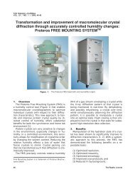
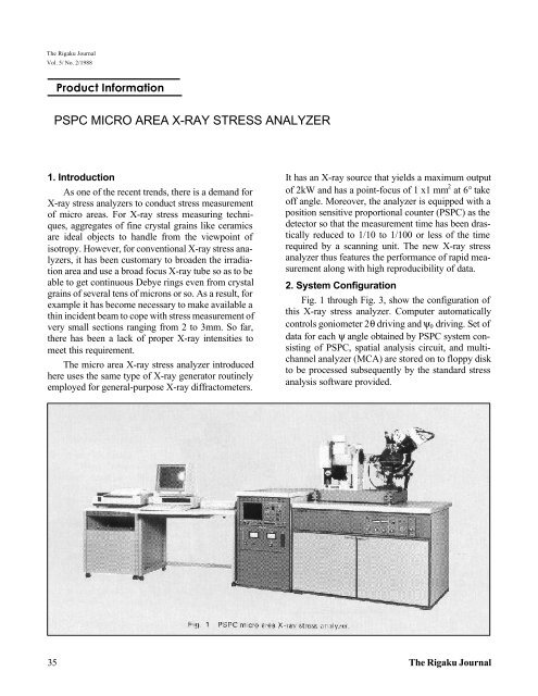
Fig. 1 through Fig. 3, show the configuration of<br />
this X-ray stress analyzer. Computer automatically<br />
controls goniometer 2θ driving and ψ 0 driving. Set of<br />
data for each ψ angle obtained by <strong>PSPC</strong> system consisting<br />
of <strong>PSPC</strong>, spatial analysis circuit, and multichannel<br />
analyzer (MCA) are stored on to floppy disk<br />
to be processed subsequently by the standard stress<br />
analysis software provided.<br />
35 The <strong>Rigaku</strong> Journal
3. Specifications<br />
(1) Goniometer<br />
X-ray source-to-sample distance: 205 mm<br />
Sample-to-detector distance:<br />
280 mm<br />
Incidence slit 4, 2, 1, 0.5, 0.3, 0.1 5 mm di a.<br />
ψ measuring range:<br />
Iso-inclination method: ψ 0 =−35° ~ 50° method<br />
Side-inclination method: ψ 0 =-3° ~ 48°<br />
Tilt oscillation angle of X-ray incidence: ± l° ~ 1-°, available only for the iso-inclination method<br />
Driving:<br />
2θ driving, with a digital motor<br />
ψ 0 driving, with a digital motor<br />
Alignment method:<br />
Microscope method or optical reflection method<br />
Arm (horizontal) length:<br />
Iso-inclination method: 150 mm or less<br />
Side-inclination method:<br />
240 mm or less<br />
(2) Standard sample stage<br />
Sample stage dimensions: 200 x 300 mm 2<br />
Fine adjustment direction:<br />
Front-rear, right-left, height and arc<br />
Front-rear stroke:<br />
20 mm<br />
Right-left stroke:<br />
20 mm<br />
Height direction:<br />
30 mm<br />
Arc adjustment: ± 30°<br />
Between sample plane and sample stage: 20~ 50mm<br />
Max. load amount Approx.:<br />
3 kgf<br />
(3) Software<br />
(i) Residual stress measurement program (iso-inclination method, side-inclination method)<br />
(ii) Residual stress analysis program<br />
• Peak position determination: Smoothing, background subtraction, LP correction, peak position determination<br />
(FWHM mid-point method, center of gravity method, parabolic approximation method)<br />
• Data output: 2θ peak angle, max. intensity, FWHM, integral width, integrated intensity, stress value, reliability<br />
limit of stress value, slope, 2θ-sin 2 ψ diagram<br />
(iii) Retained austenite quantitative measurement program.<br />
(iv) Retained austenite quantitative data analysis program<br />
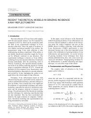
Fig. 2 Goniometer<br />
Vol. 5 No. 2 1988 36
Fig. 3 System block diagram<br />
4. Measurement Example<br />
(1) Test piece<br />
β-Silicone nitride (Si 3 N 4 ) and carbon steel (S45C)<br />
that were vacuum brazed by the active metal<br />
method<br />
(2) Measured portion<br />
Jointed surface<br />
(3) Measurement condition<br />
X-ray tube Cr(Kα), 30 kV, 45 mA<br />
Collimator: 0.3, 0.5, 1 mm dia.<br />
ψ angle: Side-inclination method<br />
ψ = 0, 1 5, 2 5, 30, 40°<br />
Stress constant K=-90.08kg/mm 2 /deg.<br />
(4) X-ray irradiation<br />
When stresses concentrate in an exceedingly<br />
small portion of the jointed surface as in the case of<br />
this sample, smoothing of the profile of a stress distribution<br />
curve can be made depending upon the area of<br />
X-ray irradiation. Fig. 4 shows the relations between<br />
the divergent optical system of the micro area X-ray<br />
stress analyzer and the irradiation area when the sideinclination<br />
method is applied.<br />
The collimator is referred to in terms of d, the<br />
pinhole diameter. The divergence angle ω is determined<br />
by the scatter pinhole φS and the collimator<br />
length L 1. The designed values are shown in Table 1.<br />
The irradiation area φA will extend as the incidence<br />
angle ψ is inclined. Eq. (1) represents the relationship<br />
between the irradiation area φA and the incidence<br />
angle ψ<br />
Fig. 4 X-ray optical system and irradiated area A for<br />
residual stress measurements with collimated X-rays.<br />
Table 1. The variation of X-ray irradiated area φA<br />
with collimated diameter φd and divergent angle ω.<br />
φd ω° φA(ψ=0) φA(ψ=40)<br />
0.1 0.13 0.15 0.38<br />
0.3 0.40 0.41 0.53<br />
0.5 0.68 0.67 0.88<br />
1 1.32 1.36 1.77<br />
37 The <strong>Rigaku</strong> Journal
where<br />
[<br />
A = d − 2 tan θ<br />
1<br />
( )<br />
+ l<br />
⎛ 2<br />
1 ⎞<br />
⎜ ⎟ + ⎛ 1 ⎞<br />
⎜ ⎟ − 2cos<br />
θ1<br />
+ θ ⎤<br />
2 ⎥ 1<br />
⎝cos<br />
θ1<br />
⎠ ⎝cos<br />
θ2<br />
⎠ cos θ1 ⋅cos θ 2<br />
cos ψ<br />
⎦⎥<br />
(1)<br />
tan θ 1 =(S-d)/2L 1<br />
tan θ 2 =(S+d)/2L 1<br />
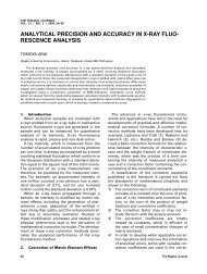
(5) Measurement result<br />
Fig. 5 shows the measurement result of a residual<br />
stress distribution in the longitudinal direction on the<br />
center line of the sample by the use of collimators 0.3,<br />
0.5 or 1 mm diameter. The abscissa denotes the distance<br />
from the jointed surface on the center line of the<br />
Si 3 N 4 surface, and the ordinate represents the residual<br />
stress value. The circles on the center line indicate the<br />
X-ray irradiation area at ψ=40° for the respective collimators.<br />
For reference, shown on the ordinate are the<br />
sample width values identical to those on abscissa.<br />
5. Conclusion<br />
As mentioned above, this new rapid X-ray stress<br />
analyzer provides high X-ray intensities from a 2 kW<br />
X-ray tube and is equipped with a <strong>PSPC</strong>. These design<br />
characteristics have made it possible to carry out<br />
measurements that were previously considered difficult.<br />
It offers a substantial reduction in the measurement<br />
time, with improved data reproducibility.<br />
Also available is an optional system with the X-Y<br />
stage used as the sample stage with a stepping motor<br />
to permit automatic shifting of the measurement area<br />
Fig. 5. Residual stress distribution with different<br />
irradiated area on the same specimen A.<br />
position by computer control. Continuous storage of<br />
collected measurement data is made on a floppy disk.<br />
Thus, the micro area stress analyzer is expected to<br />
find a wide range of application for the future.<br />
Reference<br />
S. Tanaka, K. Oguiso, collected lecture papers for the 25th<br />
Symposium on X-ray Material Strength, p. 213, Jul. '88,<br />
The Society of Materials Science, Japan.<br />
Vol. 5 No. 2 1988 38