PSPC MICRO AREA X-RAY STRESS ANALYZER - Rigaku
PSPC MICRO AREA X-RAY STRESS ANALYZER - Rigaku
PSPC MICRO AREA X-RAY STRESS ANALYZER - Rigaku

Create successful ePaper yourself
Turn your PDF publications into a flip-book with our unique Google optimized e-Paper software.
3. Specifications<br />
(1) Goniometer<br />
X-ray source-to-sample distance: 205 mm<br />
Sample-to-detector distance:<br />
280 mm<br />
Incidence slit 4, 2, 1, 0.5, 0.3, 0.1 5 mm di a.<br />
ψ measuring range:<br />
Iso-inclination method: ψ 0 =−35° ~ 50° method<br />
Side-inclination method: ψ 0 =-3° ~ 48°<br />
Tilt oscillation angle of X-ray incidence: ± l° ~ 1-°, available only for the iso-inclination method<br />
Driving:<br />
2θ driving, with a digital motor<br />
ψ 0 driving, with a digital motor<br />
Alignment method:<br />
Microscope method or optical reflection method<br />
Arm (horizontal) length:<br />
Iso-inclination method: 150 mm or less<br />
Side-inclination method:<br />
240 mm or less<br />
(2) Standard sample stage<br />
Sample stage dimensions: 200 x 300 mm 2<br />
Fine adjustment direction:<br />
Front-rear, right-left, height and arc<br />
Front-rear stroke:<br />
20 mm<br />
Right-left stroke:<br />
20 mm<br />
Height direction:<br />
30 mm<br />
Arc adjustment: ± 30°<br />
Between sample plane and sample stage: 20~ 50mm<br />
Max. load amount Approx.:<br />
3 kgf<br />
(3) Software<br />
(i) Residual stress measurement program (iso-inclination method, side-inclination method)<br />
(ii) Residual stress analysis program<br />
• Peak position determination: Smoothing, background subtraction, LP correction, peak position determination<br />
(FWHM mid-point method, center of gravity method, parabolic approximation method)<br />
• Data output: 2θ peak angle, max. intensity, FWHM, integral width, integrated intensity, stress value, reliability<br />
limit of stress value, slope, 2θ-sin 2 ψ diagram<br />
(iii) Retained austenite quantitative measurement program.<br />
(iv) Retained austenite quantitative data analysis program<br />
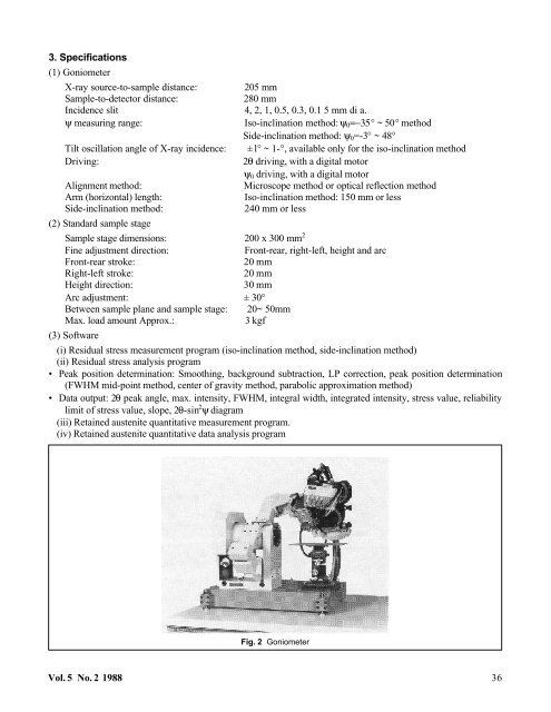
Fig. 2 Goniometer<br />
Vol. 5 No. 2 1988 36