User manual with QRP2 - Aimpoint
User manual with QRP2 - Aimpoint
User manual with QRP2 - Aimpoint

You also want an ePaper? Increase the reach of your titles
YUMPU automatically turns print PDFs into web optimized ePapers that Google loves.
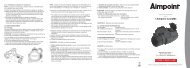
NOTE: The Rubber Cover shall be mounted to the CompM3 after the<br />
sight has been installed in the ring.<br />
a) Put the front part of the sight into the lower opening of the Rubber<br />
Cover and pull the Cover backwards over the rear part of the sight.<br />
Be careful not to pull too hard and far, the rubber could be destroyed<br />
b) Install the lens covers over the front and rear Lens.<br />
c) Install the rubber strap on to the protective adjustment caps and<br />
battery cap.<br />
To remove the rubber cover from the Sight, do the opposite way.<br />
Start to pull off the rear part of the sight. Hold the lower rear part<br />
of the rubber cover, and pull the rubber backwards and up over the<br />
sight.<br />
2.2 OPERATING PROCEDURES<br />
2.2.1 ZEROING<br />
The <strong>Aimpoint</strong> sights are delivered in a centered position. Normally<br />
this means that only small adjustments are necessary, providing that<br />
the base(s) are properly aligned.<br />
CAUTION: Do not continue to adjust windage and elevation<br />
mechanisms if you encounter resistance. The elevation adjustment<br />
screw is located on top of the sight, while the windage screw is<br />
located on the right side of the sight.<br />
a) Open front and rear lens covers.<br />
b) Turn the rotary switch clockwise until the red dot has a sufficient<br />
intensity to contrast against the target.<br />
c) Remove the windage and elevation adjustment caps.<br />
NOTE: Each click of the adjustment screw corresponds to a 16 mm<br />
movement of the point of impact at 100 meters.<br />
d) Insert adjustment tool (coin, screwdriver, knife) or cartridge casing<br />
in adjustment screw slot and turn as follows:<br />
• To move the point of impact to the right, turn side adjustment screw<br />
counter clockwise (clockwise if screw located on left side).<br />
• To move the point of impact to the left, turn side adjustment screw<br />
clockwise (counter clockwise if screw located on left side).<br />
• To move the point of impact up, turn elevation adjustment screw<br />
counter clockwise.<br />
• To move the point of impact down, turn elevation adjustment screw<br />
clockwise.<br />
e) Confirm zero field by firing at least three shots at a zero field target.<br />
Check impact points on zero field target to confirm accuracy and<br />
repeat above procedure if required.<br />
f) After initial firing, ensure that the mount and sight are secure.<br />
g) Turn rotary switch to OFF position (counter clockwise).<br />
h) Close front and rear lens covers.<br />
CHAPTER III<br />
OPERATION UNDER EXTREME CONDITIONS<br />
a) Extreme heat (moist or dry). No special procedures required.<br />
b) Extreme cold. Extreme cold might shorten battery life.<br />
c) Salt air. No special procedures required.<br />
d) Sea spray, water, mud and snow. Ensure that battery cap and<br />
two adjustment screw caps are tight before exposing the sight to<br />
sea spray, mud, snow or before lower down the sight in water. Hand<br />
tighten only. Keep lens covers closed when sight is not being used.<br />
Clean lenses <strong>with</strong> lens paper/cloth and wipe the sight dry as soon as<br />
possible after exposure to water, sea spray, mud or snow.<br />
e) Dust storms and sand storms. Keep lens caps closed when sight<br />
is not being used.<br />
f) High altitudes. No special procedures required.<br />
CAUTION: The lenses shall never be cleaned <strong>with</strong> fingers but <strong>with</strong><br />
lens paper/cloth. If no lens paper/cloth available:<br />
– To clear away debris (sand, grass etc.): blow away the dirt.<br />
– To clean lenses: mist up the lenses and dry them <strong>with</strong> a clean and<br />
soft piece of cloth.<br />
CHAPTER IV<br />
TROUBLE SHOOTING PROCEDURES<br />
4.1 RED DOT DOES NOT APPEAR<br />
Discharged battery: Replace battery<br />
Battery installed incorrectly: Remove and reinstall battery <strong>with</strong> (+)<br />
toward cap<br />
Battery is not making good contact: Clean contact surfaces and<br />
reinstall battery.<br />
Defective rotary switch: Notify dealer.<br />
4.2 IMPOSSIBLE TO ZERO<br />
Adjustment screw is at its limit: Check alignment of mount to barrel.<br />
Impact point is moving: Check mount stability.<br />
CHAPTER V<br />
MAINTENANCE<br />
a) This reflex sight does not require any particular maintenance<br />
while used under normal conditions.<br />
b) Under severe weather conditions please refer to Chapter III.<br />
c) Keep lens covers closed whenever the sight is not in use.<br />
d) Warehouse storage: Remove battery and allow lens surfaces to<br />
dry completely (if wet) before closing the lens covers.<br />
e) To clean lenses refer to Caution in Chapter III.<br />
Operator and Maintenance Manual<br />
for<br />
<strong>Aimpoint</strong> CompM3<br />
<strong>with</strong> <strong>QRP2</strong><br />
<strong>Aimpoint</strong> AB<br />
Jägershillgatan 15<br />
SE- 213 75 Malmö, Sweden<br />
Phone +46 (0)40 671 50 20<br />
Fax +46 (0)40 21 92 38<br />
e-mail: info@aimpoint.se<br />
www.aimpoint.com<br />
© Copyright 2012. Contents property of <strong>Aimpoint</strong>. All rights reserved. 13385-0
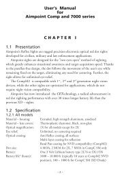
CHAPTER I<br />
1.1 PRESENTATION<br />
The <strong>Aimpoint</strong> M3 Sight is a rugged precision electronic optical red<br />
dot sight developed for military and law enforcement applications.<br />
The <strong>Aimpoint</strong> red dot sights are designed for the two eyes open<br />
method of sighting, which greatly enhances situational awareness<br />
and target acquisition speed. Due to the optic design, the dot follows<br />
the movement of the user’s eye while remaining fixed on the target,<br />
eliminating any need for centering. Further, the sights allows for<br />
unlimited eye-relief and is compatible <strong>with</strong> all generations of night<br />
vision devices.<br />
The <strong>Aimpoint</strong> M3 sight includes the enhanced ACET technology<br />
that provides roughly 5 years of constant use <strong>with</strong>out replacing the<br />
included battery.<br />
1.2 SPECIFICATION<br />
Material – housing:<br />
Surface finish:<br />
Rubber cover:<br />
Optical magnification:<br />
Eye relief:<br />
Optical coating:<br />
Extruded,<br />
High strength aluminum,<br />
Anodized<br />
Hard Anodized,<br />
Dark Graphite Grey, matte<br />
Black or Dark Brown<br />
1X<br />
Unlimited, no centering required<br />
Anti Reflex coating,<br />
all surfaces Multi-layer coating<br />
for reflection Band Pass coating<br />
for NVD compatibility<br />
Dot size:<br />
Switch Dot brightness:<br />
Battery:<br />
2MOA<br />
10 positions: 4 NVD, 6 daylight<br />
of which 1Extra Bright.<br />
One 3 Volt Lithium battery<br />
type 2L76 or DL1/3N<br />
Battery life (hours): 50 000 h on setting 7 out of 10,<br />
(ACET Diode)Typically 500 000 h<br />
at NVD setting.<br />
Length (inclusive lens covers): 130mm<br />
Width:<br />
Height:<br />
Weight:<br />
Adjustment:<br />
Mounting:<br />
55 mm<br />
55 mm<br />
322 gram <strong>with</strong> <strong>QRP2</strong> mount<br />
Range ±2 meters at 100 meters,<br />
in windage and elevation<br />
=16 mm at 100 meters.<br />
Ring Base & Top, <strong>QRP2</strong> mount<br />
Max temperature range: -45 ºC to +70 ºC<br />
Water resistance:<br />
Accessories<br />
Material for Rubber Cover:<br />
Material for Lens Covers:<br />
MOA: Minute Of Angle 1MOA = 30 mm at 100 meters<br />
NVD: Night Vision Device<br />
Submersible to 45 m water depth<br />
Chloroprene rubber<br />
(corresponding to MIL-R-6855).<br />
Thermoplastic elastomer,<br />
black, non-glare.<br />
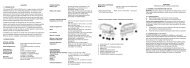
1.3 LOCATION AND DESCRIPTION OF MAJOR COMPONENTS<br />
AND FUNCTIONS<br />
1. Rubber cover 7. Lens Cover, front<br />
2. Cover for adjustment screw 8. <strong>QRP2</strong><br />
3. Adjustment Screw (elevation) 9. Ring Top<br />
4. Battery Lid 10. Screw 4pcs<br />
5. Battery (DL1/3N) 11. Rubber Strap<br />
6. Lens Cover, rear 12. Allen Wrench<br />
CHAPTER II<br />
OPERATION UNDER NORMAL CONDITIONS<br />
2.1 ASSEMBLY AND PREPARATION FOR USE<br />
WARNING: Insure the weapon is unloaded and the safety selector is<br />
in the ”safe” position before attempting to install, remove or perform<br />
maintenance on the sight.<br />
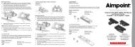
2.1.1 INSTALLING BATTERY<br />
a) Remove battery cap by turning it counter clockwise.<br />
b) Insert battery <strong>with</strong> positive (+) end toward cap.<br />
Caution while replacing battery (not necessary when the sight is<br />
unused). Before installing battery cap, inspect that the O-ring is<br />
present and not damaged. Failure to do so could result in water<br />
leakage into the battery compartment.<br />
c) Install battery cap by turning clockwise until snug. Hand tighten<br />
only. Using tools could damage equipment.<br />
d) Verify that red dot is present by turning the rotary switch clockwise.<br />
2.1.2 INSTALLING THE RUBBER COVER, LENS COVERS AND<br />
RUBBER STRAP