
You also want an ePaper? Increase the reach of your titles
YUMPU automatically turns print PDFs into web optimized ePapers that Google loves.
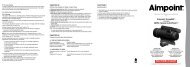
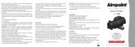
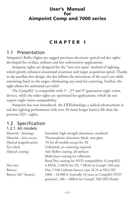
<strong>User</strong>’s Manual<br />
for<br />
<strong>Aimpoint</strong> Comp and 7000 series<br />
CHAPTER I<br />
1.1 Presentation<br />
<strong>Aimpoint</strong>’s Reflex Sights are rugged precision electronic optical red dot sights<br />
developed for civilian, military and law enforcement applications.<br />
<strong>Aimpoint</strong> sights are designed for the ”two eyes open” method of sighting,<br />
which greatly enhances situational awareness and target acquisition speed. Thanks<br />
to the parallax-free design, the dot follows the movement of the user’s eye while<br />
remaining fixed on the target, eliminating any need for centering. Further, the<br />
sight allows for unlimited eye-relief.<br />
The CompM2 is compatible with 1 st , 2 nd and 3 rd generation night vision<br />
devices, while the other sights are optimized for applications, which do not<br />
require night vision compatibility.<br />
<strong>Aimpoint</strong> has now introduced the CETechnology, a radical advancement in<br />
red dot sighting performance with over 30 times longer battery life than the<br />
previous XD – sights.<br />
1.2 Specification<br />
1.2.1 All models<br />
Material – housing:<br />
Material – lens covers:<br />
Optical magnification:<br />
Eye relief:<br />
Optical coating:<br />
Dot size:<br />
Battery:<br />
Battery life* (hours):<br />
Extruded, high strength aluminum, anodized<br />
Thermoplastic elastomer, black, non-glare<br />
1X for all models except for 2X<br />
Unlimited, no centering required<br />
Anti Reflex coating, all surfaces<br />
Multi-layer coating for reflection<br />
Band Pass coating for NVD compatibility (CompM2)<br />
4 MOA, 2 MOA for 2X, 7 MOA in CompC SM only<br />
One 3 Volt Lithium battery type 2L76 or DL1/3N<br />
1000 – 10.000 h (typically 10 years at CompM2 NVD<br />
position), 100 – 1000 h for CompC SM (XD Diode)<br />
– 2 –
Adjustment:<br />
Range ±2 m at 100 meters, in windage and elevation<br />
1 click = 10 mm at 80 meters = 13 mm at 100 meters =<br />
= 1 / 2" at 100 yards.<br />
*) Average values, depending on brightness setting<br />
MOA: Minute Of Angle 1MOA = 30 mm at 100 meters = 1" at 100 yards<br />
NVD: Night Vision Device<br />
1.2.2 Model 7000SC, 7000L, 7000SC-2X and 7000L-2X<br />
Length: 7000SC: 160 mm (6.3") 7000SC-2X: 195 mm (7.7")<br />
7000L: 200 mm (7.9") 7000L-2X: 235 mm (9.3")<br />
Width / height 7000SC/L: 55 mm (2.2") 7000SC/L-2X: 60 mm (2.4")<br />
Weight:<br />
7000SC: 200 gram (7.0 oz) 7000SC-2X: 290 gram (10.2 oz)<br />
7000L: 225 gram (7.9 oz) 7000L-2X: 315 gram (11.1 oz)<br />
Surface finish:<br />
Carbon Black or Silver Metalic/SM (only 7000SC), semi-matte<br />
Mounting:<br />
2 rings, 30 mm diameter<br />
Distance between rings: 7000SC: min 50 mm (2.0"), max 115 mm (4.5")<br />
7000L: min 60 mm (2.4"), max 155 mm (6.1")<br />
Switch, dot brightness: 10 pos.: 1 Off, 9 daylight of which 1 Extra Bright<br />
Max temperature range: -30°C to +60°C (-20°F to +140°F)<br />
Water resistance: Waterproof to 2 m (7 ft) water depth<br />
1.2.3 Model CompC and CompC-2X<br />
Length: CompC: 120 mm (4.7") CompC-2X: 155 mm (6.1")<br />
Width / height: CompC: 55 mm (2.2") CompC-2X: 60 mm (2.4")<br />
Weight:<br />
CompC: 185 gram (6.5 oz) CompC-2X: 275 gram (9.7 oz)<br />
Surface finish:<br />
Carbon Black or Silver Metallic/SM (only CompC), semi-matte<br />
Mounting:<br />
One wide ring, 30 mm diameter<br />
Switch, dot brightness: 10 pos.: 1 Off, 9 daylight of which 1 Extra Bright<br />
Max temperature range: -30°C to +60°C (-20°F to +140°F)<br />
Water resistance: Waterproof to 2 m (7 ft) water depth<br />
1.2.4 Model CompM2, CompML2, CompM2-2X and CompML2-2X<br />
Length (incl. lens covers): CompM2 / ML2: 130 mm (5.1")<br />
CompM2-2X / ML2-2X: 165 mm (6.5")<br />
Width / height: CompM2 / ML2: 55 mm (2.2")<br />
CompM2-2X / ML2-2X: 60 mm (2.4")<br />
Weight (incl. lens covers): CompM2 / ML2: 200 gram (7.1 oz)<br />
CompM2-2X / ML2-2X: 290 gram (10.2 oz)<br />
– 3 –
Surface finish:<br />
Hard Anodized, Graphite Grey, matte<br />
Mounting:<br />
One wide ring, 30 mm diam, or <strong>Aimpoint</strong> QR Ring<br />
Switch, dot brightness: CompM2 / M2-2X: 10 positions:<br />
4 NVD, 6 daylight of which 1 Extra Bright<br />
CompML2 / ML2-2X: 10 positions:<br />
1 Off, 9 daylight of which 1 Extra Bright<br />
Max temperature range: -45°C to +70°C (-50°F to +160°F)<br />
Water resistance: Submersible to 25 m (80 ft) water depth*<br />
*) Tests performed have shown that sights will stand over 100 meters (330 ft) of water depth.<br />
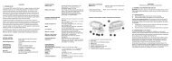
1.3 Location and description of major<br />
components and functions<br />
See fig. 1 and 2<br />
1. Battery Lid 7. Rubber Strap<br />
2. Battery (for CompM2 and ML2 models)<br />
(DL1/3N or similar) 8. Eye Protection<br />
3. Cover for adjustment screw 9. Lens Cover, rear<br />
4. Adjustment Screw (for CompM2 and ML2 models)<br />
(windage/elevation)<br />
10. Lens Cover, front<br />
5. Rotary Switch (for CompM2 and ML2 models)<br />
6. Rubber Strap 11. Lens Cover for 2X<br />
(for 7000 models and CompC) (for CompM2 and ML2 models)<br />
CHAPTER II<br />
OPERATION UNDER NORMAL CONDITIONS<br />
2.1. Assembly and preparation for use<br />
WARNING: Insure the weapon is unloaded and the safety selector is in the ”safe”<br />
position before attempting to install, remove or perform maintenance on the sight.<br />
2.1.1.Installing Battery<br />
a) Remove battery cap by turning it counterclockwise.<br />
b) Insert battery with positive (+) end toward cap.<br />
– 4 –
Caution while replacing battery (not necessary when the sight is unused)<br />
Before installing battery cap, inspect that the O-ring is present and not damaged.<br />
Failure to do so could result in water leakage into the battery compartment.<br />
c) Install battery cap by turning clockwise until snug. Hand tighten only. Using<br />
tools could damage equipment.<br />
d) Verify that red dot is present by turning the rotary switch clockwise.<br />
2.1.2.Installing Ring and Sight on the weapon<br />
<strong>Aimpoint</strong>’s sights are designed for installation on most types of weapons. For<br />
mounting, certain models come with one or two rings, for other models use standard<br />
rings available on the market. If your weapon does not have or support an<br />
appropriate base(s), please consult your dealer, gunsmith or other qualified source.<br />
a) When using two separate bases on the weapon, ensure that the bases are<br />
parallel and aligned.<br />
b) Assemble the ring(s) on the appropriate weapon base (a Weaver or Picatinny<br />
base). When using 2 rings, make sure that the distance between the rings is<br />
appropriate to the sight.<br />
Note: make sure that you have space between the bottom front part of the<br />
sight and the top of the base/weapon.<br />
c´) For Comp models: Assemble the sight to the weapon by using <strong>Aimpoint</strong>´s<br />
wide 30 mm ring or QR-mount. If other standard 30 mm<br />
rings are used, make sure that the ring(s) covers a length<br />
of minimum 25 mm or 1" (two standard rings could possibly<br />
be used).<br />
c") For 7000 models: Assemble the sight to the weapon with any standard 30<br />
mm rings.<br />
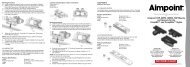
d) Ensure that the sight is correctly positioned for right or left hand shooting, see<br />
fig 3 and 4.<br />
e) When using lens covers, ensure that they are correctly positioned and can be<br />
opened.<br />
f) Finally, make sure that all screws are firmly tightened around the sight.<br />
g) Complete the zeroing (2.2.1).<br />
– 5 –
2.2. OPERATING PROCEDURES<br />
2.2.1.Zeroing<br />
<strong>Aimpoint</strong>’s sights are delivered in a centered position. Normally this means that<br />
only small adjustments are necessary, providing that the base(s) are properly aligned.<br />
CAUTION: Do not continue to adjust windage and elevation mechanisms if you<br />
encounter resistance.<br />
The elevation adjustment screw is located on top of the sight, while the windage<br />
screw is located on the right or left side, depending on how the sight has been<br />
mounted on the weapon. (<strong>Aimpoint</strong> sights can be installed to support either right<br />
hand (fig 3) or left hand (fig 4) shooters.)<br />
a) Open front and rear lens covers.<br />
b) Turn the rotary switch clockwise until the red dot has a sufficient intensity to<br />
contrast against the target.<br />
c) Remove the windage and elevation adjustment caps.<br />
NOTE: Each click of the adjustment screw corresponds to a 10 mm movement of<br />
the point of impact at 80 meters, (3 mm at 25 meters, 13 mm at 100 meters and<br />
25 mm at 200 meters or 1 / 4" at 50 yds, 1 / 2" at 100 yds and 1" at 200 yds).<br />
d) Insert adjustment tool (coin, screwdriver, knife) or cartridge casing in adjustment<br />
screw slot and turn as follows:<br />
• To move the point of impact to the right, turn windage adjustment screw<br />
counterclockwise (clockwise if screw located on left side).<br />
• To move the point of impact to the left, turn windage adjustment screw<br />
clockwise (counterclockwise if screw located on left side).<br />
• To move the point of impact up, turn elevation adjustment screw counterclockwise.<br />
• To move the point of impact down, turn elevation adjustment screw clockwise.<br />
e) Confirm zeroing by firing at least three shots at a zeroing target. Check impact<br />
points on zeroing target to confirm accuracy and repeat above procedure if required.<br />
f) After initial firing, ensure that the mount and sight are secure.<br />
g) Turn rotary switch to OFF position (counterclockwise).<br />
h) Close front and rear lens covers.<br />
– 6 –
CHAPTER III<br />
Operation under extreme conditions<br />
a) Extreme heat (moist or dry). No special procedures required.<br />
b) Extreme cold. Extreme cold might shorten battery life. Keep spare batteries in<br />
your inner pockets to keep them warm.<br />
c) Salt air. No special procedures required.<br />
d) Sea spray, water, mud and snow. Ensure that battery cap and two adjustment<br />
screw caps are tight before exposing the sight to sea spray, mud, snow or before<br />
immersing the sight in water. Hand tighten only.<br />
Keep lens covers closed when sight is not being used. Clean lenses with lens<br />
paper/cloth and wipe the sight dry as soon as possible after exposure to water,<br />
sea spray, mud or snow.<br />
e) Dust storms and sand storms. Keep lens caps closed when sight is not being<br />
used.<br />
f) High altitudes. No special procedures required.<br />
CAUTION: The lenses shall never be cleaned with fingers but with lens paper/<br />
cloth.<br />
If no lens paper/cloth available :<br />
– To clear away debris (sand, grass etc): blow away the dirt.<br />
– To clean lenses: mist up the lenses and dry them with a clean and soft piece of<br />
cloth.<br />
CHAPTER IV<br />
Trouble shooting procedures<br />
4.1 Red dot does not appear<br />
Discharged battery:<br />
Replace battery<br />
Battery installed incorrectly:<br />
Remove and reinstall battery with<br />
(+) toward cap<br />
Battery is not making good contact: Clean contact surfaces and<br />
reinstall battery.<br />
Defective rotary switch:<br />
Notify dealer/armourer<br />
– 7 –
4.2 Impossible to zero<br />
Adjustment screw is at its limit:<br />
Impact point is moving:<br />
Check alignment of mount to barrel<br />
Check mount stability<br />
CHAPTER V<br />
MAINTENANCE<br />
a) This reflex sight does not require any particular maintenance while used under<br />
normal conditions.<br />
b) Under severe weather conditions please refer to chapter III.<br />
c) Keep lens covers closed whenever the sight is not in use.<br />
d) Warehouse storage: Remove battery and allow lens surfaces to dry completely<br />
(if wet) before closing the lens covers.<br />
e) To clean lenses refer to CAUTION in chapter III.<br />
– 8 –
Fig 1
Fig 2
Fig 3<br />
Fig 4