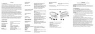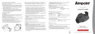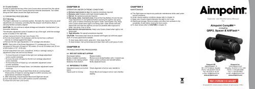
Aimpoint CompM4⢠QRP2, Spacer & killFlashâ¢
Aimpoint CompM4⢠QRP2, Spacer & killFlashâ¢
Aimpoint CompM4⢠QRP2, Spacer & killFlashâ¢

Create successful ePaper yourself
Turn your PDF publications into a flip-book with our unique Google optimized e-Paper software.
2.1.3 Lens Covers<br />
In order to preclude the loss of the Lens Covers when removed from the optical<br />
path of the Sight, the Lens Covers should be removed downwards. The rubber<br />
string will then attach around the Sight and mount.<br />
2.2 OPERATING PROCEDURES<br />
2.2.1 Zeroing<br />
The Sight is delivered in a centered position. Normally this means that only small<br />
adjustments are necessary, providing that the weapon rail (Picatinny Rail) or<br />
carrying handle is properly aligned.<br />
CAUTION: Do not continue to adjust windage and elevation mechanisms if you<br />
encounter resistance.<br />
The elevation adjustment screw is located on top of the sight, while the windage<br />
screw is located on the right side.<br />
a) Open (remove) front and rear Lens Covers (13).<br />
b) Turn the Knob Switch (10) clockwise until the red dot has a sufficient<br />
intensity to contrast against the target.<br />
c) Remove the the Caps Adjustment (1) for windage and elevation.<br />
NOTE: Each click of the Screw Adjustment (11) corresponds to a 16 mm<br />
movement of the point of impact at 100 meters, (4 mm at 25 meters and 32 mm<br />
at 200 meters or 1⁄2” at 80 yds).<br />
d) Insert adjustment tool (coin, screwdriver, knife) or cartridge casing in<br />
adjustment screw slot and turn as follows:<br />
• To move the point of impact to the right, turn windage adjustment<br />
screw counter clockwise<br />
• To move the point of impact to the left, turn windage adjustment<br />
screw clockwise<br />
• To move the point of impact up, turn elevation adjustment screw<br />
counter clockwise.<br />
• To move the point of impact down, turn elevation adjustment screw<br />
clockwise.<br />
e) Confirm zeroing by firing at least three shots at a zeroing target.<br />
Check points of impact on zeroing target to confirm accuracy and<br />
repeat above procedure if required.<br />
f) After initial firing, ensure that the Mount and Sight are secure.<br />
g) Turn Knob Switch (10) to OFF position (counter clockwise).<br />
h) Close front and rear Lens Covers.<br />
CHAPTER III<br />
Operation under extreme conditions<br />
a) Extreme heat (moist or dry). No special procedures required.<br />
b) Extreme cold. Extreme cold might shorten battery life.<br />
c) Salt air. No special procedures required.<br />
d) Sea spray, water, mud and snow. Ensure that Cap Battery (4) and the two<br />
Caps Adjustment (1) are tightened before exposing the sight to sea spray,<br />
mud, snow or before immersing the sight in water. Hand tighten only. Keep<br />
Lens Covers closed when sight is not being used. Clean lenses with lens<br />
paper/cloth and wipe the sight dry as soon as possible after exposure to<br />
water, sea spray, mud or snow.<br />
e) Dust storms and sand storms. Keep Lens Covers closed when sight is not<br />
being used.<br />
f) High altitudes. No special procedures required.<br />
CAUTION: The lenses shall never be cleaned with fingers but with lens paper/<br />
cloth. If no lens paper/cloth available :<br />
- To clear away debris (sand, grass etc): blow away the dirt.<br />
- To clean lenses: mist up the lenses and clean them with a soft piece of cloth.<br />
CHAPTER IV<br />
Trouble shooting procedures<br />
4.1 RED DOT DOES NOT APPEAR<br />
Discharged battery:<br />
Replace battery.<br />
Battery installed incorrectly: Remove and reinstall battery with (-) toward cap.<br />
Battery is not making contact: Clean contact surfaces and reinstall battery.<br />
Defective Knob Switch: Notify dealer/armourer.<br />
4.2 IMPOSSIBLE TO ZERO<br />
Adjustment screw is at its limit: Check alignment of rail (or carry handle) to<br />
barrel.<br />
Impact point is moving: Check Mount and weapon rail (or carry handle)<br />
stability.<br />
CHAPTER V<br />
Maintenance<br />
a) This Sight does not require any particular maintenance while used under<br />
normal conditions.<br />
b) Under severe weather conditions please refer to chapter III.<br />
c) Keep Lens Covers closed whenever the sight is not in use.<br />
d) Warehouse storage: Remove battery and allow lens surfaces to dry<br />
completely (if wet) before closing the lens covers.<br />
e) To clean lenses refer to CAUTION in chapter III.<br />
Operator and Maintenance Manual<br />
for<br />
<strong>Aimpoint</strong> CompM4<br />
including<br />
<strong>QRP2</strong>, <strong>Spacer</strong> & killFlash<br />
<strong>Aimpoint</strong> AB<br />
Jägershillgatan 15<br />
SE- 213 75 Malmö, Sweden<br />
Phone +46 (0)40 671 50 20<br />
Fax +46 (0)40 21 92 38<br />
e-mail: info@aimpoint.se<br />
www.aimpoint.com<br />
<strong>Aimpoint</strong> Inc.<br />
14103 Mariah Court<br />
Chantilly, VA 20151-2113, USA<br />
Phone +1 703-263-9795<br />
Fax +1 703-263-9463<br />
e-mail: info@aimpoint.com<br />
www.aimpoint.com<br />
© Copyright 2010. Contents property of <strong>Aimpoint</strong>. All rights reserved. 11755-1
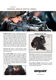
CHAPTER I<br />
1.1 Presentation<br />
<strong>Aimpoint</strong> CompM4 Reflex Sight is a rugged precision red dot Sight developed<br />
mainly for military and law enforcement applications.<br />
<strong>Aimpoint</strong> red dot sights are designed for the ”two eyes open” method of sighting,<br />
which greatly enhances situational awareness and target acquisition speed.<br />
Thanks to the parallax-free design, the dot follows the movement of the user’s eye<br />
while remaining fixed on the target, eliminating any need for centering. Further,<br />
the Sight allows for unlimited eye-relief and is compatible with 1st , 2nd and 3rd<br />
generation night vision devices.<br />
The CompM4 Sight is using a AA size battery, which together with the extremely<br />
low power consumption gives an unequalled battery life.<br />
The CompM4 combines the superior accuracy and ease of use of the well-known<br />
CompM2 model with significantly longer battery life and increased ruggedness<br />
through reinforced design.<br />
The Sight is provided with a torque knob, Quick Release (<strong>QRP2</strong>) mount.<br />
The Sight has a <strong>Spacer</strong> system that gives optimal height of the line of sight (optical<br />
axis) on different weapons.<br />
1.2 Specification<br />
Material - housing:<br />
Surface finish:<br />
Material – lens covers:<br />
Optical magnification:<br />
Eye relief:<br />
Optical coating:<br />
Dot size:<br />
Switch, dot brightness:<br />
Battery:<br />
Extruded, high strength aluminum<br />
Hard Anodized, black to dark graphite grey, matte<br />
Rubber, black<br />
1X<br />
Unlimited, no centering required<br />
Anti Reflex coating, all surfaces<br />
Multi-layer coating for reflection of red light (650 nm)<br />
Band Pass coating for NVD* compatibility<br />
2 MOA**<br />
16 positions: 7 NVD, 8 daylight and 1 Extra Bright<br />
One AA size battery, (rechargeable 1.2V),<br />
alkaline/lithium 1.5V or lithium 3-3.7V (acceptable<br />
voltage 1.2 – 5.0 V)<br />
Battery life:<br />
Over 8 years of continuous (day and night) use at<br />
pos 12 of 16 and over 3 years at pos 13 of 16.<br />
(at room temperature and with a quality battery)<br />
Typically 500 000 h at NVD setting<br />
Length: 135mm (5.3”)<br />
Width: 75mm (3”)<br />
Height: 61mm (2.4”), with <strong>Spacer</strong> 70mm (2.8”)<br />
Weight:<br />
Adjustment:<br />
Mounting:<br />
Height of optical axis***:<br />
Max temperature range:<br />
Water resistance:<br />
370g (13.1 oz), with <strong>Spacer</strong> 395g (14 oz)<br />
Range ±2 m at 100 meters (±2 yds at 100 yds), in<br />
windage and elevation, 1 click = 4 mm at 25 meters<br />
= 16 mm at 100 meters ~ 1⁄2” at 80 yards<br />
On a MIL-Std 1913 Picatinny Rail. A <strong>Spacer</strong> is<br />
available for optimal height<br />
30 mm (1.2”) with <strong>QRP2</strong> mount, 39 mm (1.5”) with<br />
<strong>QRP2</strong> mount and <strong>Spacer</strong><br />
-45 ºC to +70 ºC (-50 ºF to +160 ºF), in storage<br />
and operation<br />
Submersible to 45 m (150 ft)<br />
* NVD: Night Vision Device<br />
** MOA (Minute Of Angle): 1MOA~ 30 mm at 100 meters or ~1” at 100 yards<br />
*** Over top surface of Picatinny Rail<br />
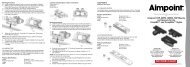
1.3 Location and description of major components<br />
See figure next page<br />
1. Cap Adjustment (2 pcs)<br />
2. Strap (for Cap Adjustment) (2 pcs)<br />
3. Battery (AA size)<br />
4. Cap Battery<br />
5. Strap (for Cap Battery)<br />
6. Screws (for Mount) (2 pcs)<br />
7. Screws (for Mount with <strong>Spacer</strong>)<br />
(2 pcs)<br />
8. Mount <strong>QRP2</strong><br />
9. <strong>Spacer</strong><br />
10. Knob, Switch<br />
11. Screw Adjustment (2 pcs)<br />
12. Knob, Torque (on Mount <strong>QRP2</strong>)<br />
13. Lens Cover (Bikini)<br />
14. Allen Wrench for screws<br />
(pos.6 and 7)<br />
15. Anti-Reflection Device (ARD)<br />
CHAPTER II<br />
Operation under normal conditions<br />
2.1 ASSEMBLY AND PREPARATION FOR USE<br />
WARNING: Ensure the weapon is unloaded and the safety selector is in the<br />
”safe” position before attempting to install, remove or perform maintenance on<br />
the sight.<br />
2.1.1 Installing Battery<br />
a) Remove Cap Battery (4) by turning it counter clockwise.<br />
b) Insert a AA-size battery with negative (-) end toward cap.<br />
Caution while replacing battery (not necessary when the sight is new).<br />
Before installing Cap Battery, inspect that the O-ring is present and not damaged.<br />
Failure to do so could result in water leakage into the battery compartment.<br />
c) Install Cap Battery by turning clockwise until snug. Hand tighten only.<br />
Using tools could damage equipment.<br />
d) Verify that red dot is present by turning the Knob Switch (10) clockwise.<br />
2.1.2 Installing Sight on the weapon<br />
The CompM4 Sight is designed for installation on most types of weapons, which<br />
have a MIL-Std 1913 Picatinny Rail.<br />
Depending on type of weapon, the optical line of sight (the centre of the lens<br />
system) may have different optimal height over the mounting rail. The height<br />
of the optical axis of the Sight alone (without <strong>Spacer</strong>) is 30 mm (1.2”). With the<br />
<strong>Spacer</strong> (9) mounted, the height of the optical axis is increased by 9 mm (0.35”).<br />
a) Assemble the Sight with the Mount <strong>QRP2</strong> (8) by means of the two short screws<br />
(6) and the Allen Wrench (14). Tighten firmly. Some thread glue (e.g. a “light”<br />
Loctite) could be used on the screw threads. See Fig A below.<br />
or<br />
aa) Assemble the Sight with the Mount <strong>QRP2</strong> (8) and the <strong>Spacer</strong> (9) by means<br />
of the two long screws (7) and the Allen Wrench (14). Tighten firmly. Some<br />
thread glue (e.g. a “light” Loctite) could be used on the screw threads. See<br />
Fig B below.<br />
b) Install the Sight to the weapon rail by using the Knob, Torque (12). Ensure<br />
that the Sight is correctly positioned and that the recoil stop fits into a groove<br />
on the Picatinny Rail. To ensure that Sight is secure, tighten Knob, Torque<br />
(12) until it snaps twice.<br />
c) When using Lens Covers, ensure that they are correctly positioned and can<br />
easily be opened/removed.<br />
d) Finally, make sure that the Knob, Torque (12) is firmly tightened around the<br />
weapon rail.<br />
e) Complete zeroing according to 2.2.1.<br />
Fig A without spacer<br />
Fig B with spacer