CHAPTER 14: Remote Sensing of Soil, Minerals, and Geomorphology
CHAPTER 14: Remote Sensing of Soil, Minerals, and Geomorphology
CHAPTER 14: Remote Sensing of Soil, Minerals, and Geomorphology

Create successful ePaper yourself
Turn your PDF publications into a flip-book with our unique Google optimized e-Paper software.
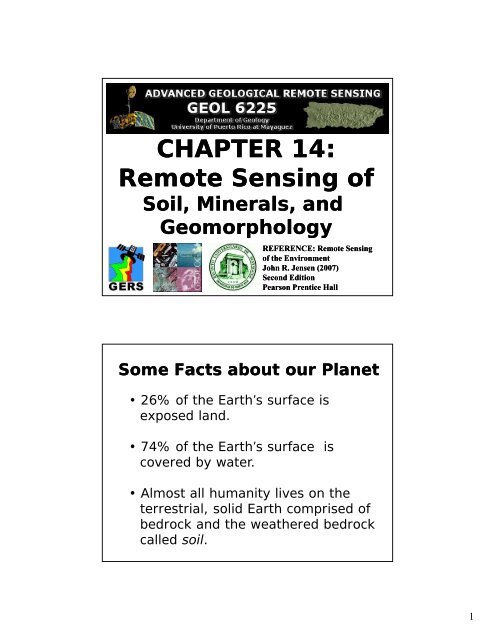
<strong>CHAPTER</strong> <strong>14</strong>:<br />
<strong>Remote</strong> <strong>Sensing</strong> <strong>of</strong><br />
<strong>Soil</strong>, <strong>Minerals</strong>, <strong>and</strong><br />
<strong>Geomorphology</strong><br />
REFERENCE: <strong>Remote</strong> <strong>Sensing</strong><br />
<strong>of</strong> the Environment<br />
John R. Jensen (2007)<br />
Second Edition<br />
Pearson Prentice Hall<br />
Some Facts about our Planet<br />
• 26% <strong>of</strong> the Earth’s surface is<br />
exposed l<strong>and</strong>.<br />
• 74% <strong>of</strong> the Earth’s surface is<br />
covered by water.<br />
Al t ll h it li th<br />
• Almost all humanity lives on the<br />
terrestrial, solid Earth comprised <strong>of</strong><br />
bedrock <strong>and</strong> the weathered bedrock<br />
called soil.<br />
1
Why <strong>Remote</strong> <strong>Sensing</strong>?<br />
• It can play a limited role in the identification, inventory, <strong>and</strong><br />
mapping <strong>of</strong> surficial soils not covered with dense vegetation.<br />
• It can provide information about the chemical composition <strong>of</strong><br />
rocks <strong>and</strong> minerals that are on the Earth’s surface, <strong>and</strong> not<br />
completely covered by dense vegetation.<br />
• Emphasis is placed on underst<strong>and</strong>ing unique absorption b<strong>and</strong>s<br />
associated with specific types <strong>of</strong> rocks <strong>and</strong> minerals using<br />
imaging i spectroscopy techniques.<br />
• It can also be used to extract geologic information including,<br />
lithology, structure, drainage patterns, <strong>and</strong> geomorphology<br />
(l<strong>and</strong>forms).<br />
<strong>Soil</strong> Characteristics<br />
• <strong>Soil</strong> is unconsolidated material at the surface <strong>of</strong> the<br />
Earth that serves as a natural medium for growing<br />
plants. Plant roots reside within this material <strong>and</strong><br />
extract water <strong>and</strong> nutrients. <strong>Soil</strong> is the weathered<br />
material between the atmosphere at the Earth’s<br />
surface <strong>and</strong> the bedrock below the surface to a<br />
maximum depth <strong>of</strong> approximately 200 cm (USDA,<br />
1998).<br />
• <strong>Soil</strong> is a mixture <strong>of</strong> inorganic mineral particles <strong>and</strong><br />
organic matter <strong>of</strong> varying size <strong>and</strong> composition. The<br />
particles make up about 50 percent <strong>of</strong> the soil’s<br />
volume. Pores containing air <strong>and</strong>/water occupy the<br />
remaining volume.<br />
2
St<strong>and</strong>ard<br />
<strong>Soil</strong> Pr<strong>of</strong>ile<br />
(U.S. Department<br />
Of Agriculture)<br />
<strong>Soil</strong> Particle Size Scales<br />
a. <strong>Soil</strong> Science Society <strong>of</strong> America <strong>and</strong> U.S. Department <strong>of</strong> Agriculture <strong>Soil</strong> Particle Size Scale<br />
S<strong>and</strong><br />
Clay<br />
Silt<br />
Gravel<br />
v. fine fine medium coarse v. coarse<br />
0.002 0.05 0.1 0.25 0.5 1 2 mm<br />
76.2<br />
Clay<br />
Silt<br />
0.15 mm<br />
Particle size relative<br />
to a grain <strong>of</strong> s<strong>and</strong><br />
0.15 mm in diameter<br />
S<strong>and</strong><br />
Clay<br />
Clay<br />
b. MIT <strong>and</strong> British St<strong>and</strong>ards Institute<br />
Silt<br />
S<strong>and</strong><br />
fine medium coarse fine medium coarse<br />
Gravel Stones<br />
0.002 0.006 0.02 0.06 0.2 0.6 2 mm<br />
c. International Society <strong>of</strong> <strong>Soil</strong> Science<br />
Silt<br />
S<strong>and</strong><br />
fine<br />
coarse<br />
Gravel<br />
0.002 0.02 0.2 2 mm<br />
3
<strong>Soil</strong> Texture Triangle<br />
100<br />
90<br />
10<br />
80<br />
20<br />
70<br />
30 read<br />
Clay<br />
60<br />
40<br />
50<br />
50<br />
read<br />
silty<br />
40 s<strong>and</strong>y<br />
clay 60<br />
clay<br />
30 clay loam<br />
silty clay<br />
70<br />
s<strong>and</strong>y clay<br />
loam<br />
20<br />
loam<br />
80<br />
Loam silt loam<br />
10<br />
s<strong>and</strong>y<br />
90<br />
loamy loam<br />
Silt<br />
S<strong>and</strong> s<strong>and</strong><br />
Clay (%)<br />
100 90 80 70 60 50 40 30 20 10<br />
S<strong>and</strong> (%)<br />
read<br />
Silt (%)<br />
100<br />
Total Upwelling Radiance (L t )Recorded<br />
by a<br />
<strong>Remote</strong> <strong>Sensing</strong> System over Exposed <strong>Soil</strong> is<br />
a Function <strong>of</strong> Electromagnetic Energy from<br />
Several Sources<br />
4
Spectral Reflectance Characteristics<br />
<strong>of</strong> <strong>Soil</strong>s Are a Function <strong>of</strong> Several<br />
Important Characteristics:<br />
• soil texture (percentage <strong>of</strong> s<strong>and</strong>,<br />
silt, <strong>and</strong> clay),<br />
• soil moisture content (e.g. dry,<br />
moist, saturated),<br />
• organic matter content,<br />
• iron-oxide content, <strong>and</strong><br />
• surface roughness.<br />
In situ Spectroradiometer<br />
Reflectance Curves for Dry<br />
Silt <strong>and</strong> S<strong>and</strong> <strong>Soil</strong>s<br />
Percent Reflectance<br />
100<br />
90<br />
80<br />
70<br />
60<br />
50<br />
40<br />
30<br />
Silt<br />
S<strong>and</strong><br />
20<br />
10<br />
0<br />
0.5 0.7 0.9 1.1 1.3 1.5 1.7 1.9 2.1 2.3 2.5<br />
Wavelength (μm)<br />
5
specular<br />
reflectance<br />
incident energy<br />
Reflectance from Dry<br />
versus Wet <strong>Soil</strong>s<br />
a.<br />
interstitial<br />
air space<br />
specular<br />
reflectance<br />
b.<br />
soil water<br />
dry<br />
soil<br />
specular reflectance<br />
volume reflectance<br />
incident energy<br />
wet<br />
soil<br />
Radiant energy may be reflected from the<br />
surface <strong>of</strong> the dry soil, or it penetrates into<br />
the soil particles, where it may be<br />
absorbed or scattered. Total reflectance<br />
from the dry soil is a function <strong>of</strong> specular<br />
reflectance <strong>and</strong> the internal volume<br />
reflectance.<br />
As soil moisture increases, each soil<br />
particle may be encapsulated with a thin<br />
membrane <strong>of</strong> capillary water. The<br />
interstitial spaces may also fill with water.<br />
The greater the amount <strong>of</strong> water in the<br />
soil, the greater the absorption <strong>of</strong> incident<br />
energy <strong>and</strong> the lower the soil reflectance.<br />
eflectance<br />
Percent Re<br />
a.<br />
ctance<br />
Percent Reflec<br />
60<br />
50<br />
40<br />
30<br />
S<strong>and</strong><br />
0 – 4% moisture content<br />
5 – 12%<br />
20<br />
22 – 32%<br />
10<br />
0<br />
0.5 0.7 0.9 1.1 1.3 1.5 1.7 1.9 2.1 2.3 2.5<br />
60<br />
Clay<br />
50 2 – 6%<br />
40<br />
30<br />
20<br />
10<br />
35 – 40%<br />
0<br />
0.5 0.7 0.9 1.1 1.3 1.5 1.7 1.9 2.1 2.3 2.5<br />
b.<br />
Wavelength (μm)<br />
Reflectance from<br />
Moist S<strong>and</strong><br />
<strong>and</strong> Clay <strong>Soil</strong>s<br />
Higher moisture content<br />
in (a) s<strong>and</strong>y soil, <strong>and</strong> (b)<br />
clayey soil results in<br />
decreased reflectance<br />
throughout the visible<br />
<strong>and</strong> near-infrared region,<br />
especially in the waterabsorption<br />
b<strong>and</strong>s at 1.4,<br />
1.9, <strong>and</strong> 2.7 μm.<br />
6
Organic<br />
Matter in<br />
a S<strong>and</strong>y<br />
<strong>Soil</strong><br />
Generally, the<br />
greater the<br />
amount <strong>of</strong><br />
organic content<br />
in a soil, the<br />
greater the<br />
absorption <strong>of</strong><br />
incident energy<br />
<strong>and</strong> the lower<br />
the spectral<br />
reflectance<br />
Iron Oxide<br />
in a S<strong>and</strong>y<br />
Loam <strong>Soil</strong><br />
Iron oxide in a<br />
s<strong>and</strong>y loam soil<br />
causes an increase<br />
in reflectance in the<br />
red portion <strong>of</strong> the<br />
spectrum (0.6 - 0.7<br />
μm) <strong>and</strong> a decrease<br />
in in near-infrared<br />
(0.85 - 0.90 μm)<br />
reflectance<br />
7
<strong>Remote</strong> <strong>Sensing</strong> <strong>of</strong><br />
Rock <strong>and</strong> <strong>Minerals</strong><br />
<strong>Remote</strong> <strong>Sensing</strong> <strong>of</strong> <strong>Soil</strong>s,<br />
<strong>Minerals</strong>, <strong>and</strong> <strong>Geomorphology</strong><br />
Rocks are assemblages <strong>of</strong> minerals that have<br />
interlocking grains or are bound together by<br />
various types <strong>of</strong> cement (usually silica or<br />
calcium carbonate). When there is minimal<br />
vegetation <strong>and</strong> soil present <strong>and</strong> the rock<br />
material is visible directly by the remote<br />
sensing system, it maybe possible to<br />
differentiate between several rock types <strong>and</strong><br />
obtain information about their characteristics<br />
using remote sensing techniques. Most rock<br />
surfaces consist <strong>of</strong> several types <strong>of</strong> minerals.<br />
8
<strong>Remote</strong> <strong>Sensing</strong> <strong>of</strong><br />
Rocks <strong>and</strong> <strong>Minerals</strong><br />
Clark (1999) suggests that it is possible to model the reflectance<br />
from an exposed rock consisting <strong>of</strong> several minerals or a single<br />
mineral based on Hapke’s (1993) equation:<br />
r λ = [[(w’/4π) x (μ / μ + μ o )] x [(1+B g )P g + H μ H μ<br />
-1<br />
o ]<br />
Where r λ is the reflectance at wavelength λ,<br />
w’ is the average single scattering albedo from the rock or mineral <strong>of</strong> interest,<br />
μ is the cosine <strong>of</strong> the angle <strong>of</strong> emitted light,<br />
u o is the cosine <strong>of</strong> the angle <strong>of</strong> incident light onto the rock or mineral <strong>of</strong> interest,<br />
g is the phase angle,<br />
B g is a back-scattering function,<br />
P g is the average single particle phase function, <strong>and</strong><br />
H is a function for isotropic scatterers.<br />
<strong>Remote</strong> <strong>Sensing</strong> <strong>of</strong> Rocks <strong>and</strong> <strong>Minerals</strong><br />
Using Spectroradiometers<br />
There are a number <strong>of</strong> processes that determine how a mineral will absorb or<br />
scatter the incident energy. Also, the processes absorb <strong>and</strong> scatter light<br />
differently depending on the wavelength (λ) <strong>of</strong> light being investigated. The<br />
variety <strong>of</strong> absorption processes (e.g., electronic <strong>and</strong> vibrational) <strong>and</strong> their<br />
wavelength dependence allow us to derive information about the chemistry <strong>of</strong> a<br />
mineral from its reflected or emitted energy. The ideal sensor to use is the<br />
imaging spectrometer because it can record much <strong>of</strong> the absorption<br />
information, much like using an in situ spectroradiometer.<br />
All materials have a complex index <strong>of</strong> refraction. If we illuminate a plane<br />
surface with photons <strong>of</strong> light from directly overhead, the light (R), will be<br />
reflected from the surface according to the Fresnel equation:<br />
R = [(n -1) 2 + K 2 ]/ [(n + 1) 2 + K 2 ]<br />
where n is the index <strong>of</strong> refraction, <strong>and</strong> K is the extinction coefficient.<br />
9
Spectra <strong>of</strong> Three<br />
<strong>Minerals</strong> Derived from<br />
NASA’s Airborne<br />
Visible Infrared<br />
Imaging Spectrometer<br />
(AVIRIS) <strong>and</strong> as<br />
Measured Using A<br />
Laboratory<br />
Spectroradiometer<br />
(after Van der Meer,<br />
1994)<br />
Alunite Laboratory Spectra, Simulated L<strong>and</strong>sat<br />
Thematic Mapper Spectra, <strong>and</strong> Spectra from a 63-<br />
Channel GERIS Instrument over Cuprite, Nevada<br />
ty)<br />
lectance (<strong>of</strong>fset for clari<br />
Percent Refl<br />
90<br />
80<br />
70<br />
60<br />
50<br />
40<br />
30<br />
20<br />
10<br />
)<br />
Percen nt Reflectance (<strong>of</strong>fset for clarity)<br />
Laboratory<br />
Spectra<br />
Alunite<br />
1 23 4 5<br />
L<strong>and</strong>sat Thematic Mapper<br />
GERIS<br />
hyperspectral<br />
23 29<br />
30 31<br />
28 32<br />
0<br />
0.4 0.6 0.8 1.0 1.2 1.4 1.6 1.8 2.0 2.2 2.4<br />
Wavelength, μm<br />
7<br />
10
Relative Refle<br />
ectance Ind<br />
ndex <strong>of</strong> <strong>of</strong> Refraction or or<br />
Ex Extinction E<br />
Coefficient Coefficient<br />
0<br />
6 Quartz Optical Constants<br />
n, index <strong>of</strong> refraction<br />
K, extinction coefficient<br />
4<br />
K<br />
2<br />
0<br />
n<br />
n<br />
n<br />
n K<br />
K<br />
8 10 12 <strong>14</strong> 16<br />
Wavelength, μm<br />
Quartz (powdered)<br />
8 10 12 <strong>14</strong> 16<br />
Wavelength, μm<br />
Index <strong>of</strong> refraction<br />
<strong>and</strong> extinction<br />
coefficient <strong>of</strong> quartz<br />
for the wavelength<br />
interval<br />
6-16 mm<br />
Spectral reflectance<br />
characteristics <strong>of</strong><br />
powdered quartz<br />
obtained using a<br />
spectroradiometer<br />
(after Clark, 1999)<br />
Mineral Maps <strong>of</strong><br />
Cuprite, NV,<br />
Derived from Low<br />
Altitude (3.9 km<br />
AGL) <strong>and</strong> High<br />
Altitude (20 km<br />
AGL) AVIRIS Data<br />
obtained on<br />
October 11 <strong>and</strong><br />
June 18, 1998<br />
Hyperspectral data were<br />
analyzed using the USGS<br />
Tetracorder program.<br />
11
<strong>Remote</strong> <strong>Sensing</strong> <strong>of</strong><br />
Geology <strong>and</strong><br />
<strong>Geomorphology</strong><br />
Geologists <strong>of</strong>ten use remote sensing in<br />
conjunction with in situ observation to<br />
identify the lithology <strong>of</strong> a rock type, i.e.,<br />
its sorigin. The edifferent e rock types ypesare<br />
formed by one <strong>of</strong> three processes;<br />
• igneous rocks are formed from moulten material;<br />
• sedimentary rocks are formed from the deposition<br />
<strong>of</strong> particles <strong>of</strong> pre-existing rocks <strong>and</strong> plant <strong>and</strong><br />
animal remains; or<br />
• metamorphic rocks are formed by applying heat<br />
<strong>and</strong> pressure to previously existing rock.<br />
12
Rock Structure: Folding <strong>and</strong> Faulting<br />
The type <strong>of</strong> rock determines how much differential stress (or<br />
compression) it can withst<strong>and</strong>. When a rock is subjected to<br />
compression, it may experience:<br />
1) elastic deformation in which case it may return to its original<br />
shape <strong>and</strong> size after the stress is removed,<br />
2) plastic deformation <strong>of</strong> rock called folding, which is<br />
irreversible (i.e., the compressional stress is beyond the elastic<br />
limit, <strong>and</strong>/or<br />
3) fracturing where the plastic limit is exceeded <strong>and</strong> the rock<br />
breaks into pieces (the pieces can be extremely large!). This may<br />
result in faulting.<br />
Rock Structure: Folding<br />
Folding takes place when horizontally bedded materials are<br />
compressed. The compression results in wavelike undulations<br />
imposed on the strata. There are four basic types <strong>of</strong> folds:<br />
• monoclines (a single fold on horizontally bedded material; like a<br />
rounded ramp),<br />
• anticlines (archlike convex upfold domes - oldest rocks in the<br />
center),<br />
• synclines (troughlike concave downfold - youngest rocks in the<br />
center),<br />
• overturned (where the folds are on top <strong>of</strong> one another):<br />
13
Effect <strong>of</strong><br />
Folding<br />
(Compressio)<br />
<strong>and</strong> Rifting<br />
(Pulling<br />
Apart) on<br />
Horizontally<br />
Bedded Strata<br />
Types <strong>of</strong><br />
Folds Found<br />
on<br />
Horizontally<br />
Bedded<br />
Terrain<br />
<strong>14</strong>
<strong>Remote</strong> <strong>Sensing</strong> <strong>of</strong><br />
Drainage Patterns<br />
<strong>Remote</strong> <strong>Sensing</strong> <strong>of</strong> Drainage Patterns<br />
Drainage patterns developed through time on a l<strong>and</strong>scape provide clues about<br />
bedrock lithology (e.g., igneous, sedimentary, metamorphic), topography<br />
(slope, aspect), the texture <strong>of</strong> the soil <strong>and</strong>/or bedrock materials, the permeability<br />
<strong>of</strong> the soil (how well water percolates through it), <strong>and</strong> the type <strong>of</strong> l<strong>and</strong>form<br />
present (e.g,. alluvial, eolian, glacial. While in situ observations are essential,<br />
physical scientists <strong>of</strong>ten use the synoptic bird’s-eye-view provided by remote<br />
sensing to appreciate regional drainage patterns, including:<br />
• Dendritic • Pinnate • Trellis • Rectangular<br />
• Parallel • Annular • Dichotomic • Braided<br />
• Deranged • Anastomotic • Sinkhole (doline)<br />
• Radial (Centrifugal) <strong>and</strong> Centripetal<br />
15
Different Drainage Patterns<br />
Different Drainage Patterns<br />
16
Different Drainage Patterns<br />
Types <strong>of</strong> Faults<br />
17
L<strong>and</strong>sat Thematic Mapper Image <strong>of</strong> the<br />
Intersection <strong>of</strong> the San Andreas <strong>and</strong><br />
Garlock Faults<br />
Garlock<br />
Fault<br />
San Andreas<br />
Fault<br />
L<strong>and</strong>sat b<strong>and</strong> 4 image<br />
Shaded relief map derived from<br />
a digital elevation model<br />
<strong>Remote</strong> <strong>Sensing</strong> <strong>of</strong><br />
Igneous L<strong>and</strong>forms<br />
18
Panchromatic<br />
Stereopair <strong>of</strong><br />
the Devil’s<br />
Tower,WY<br />
Intrusive<br />
Volcanic<br />
Neck<br />
Obtained on<br />
September 15,<br />
1953 (south is<br />
at the top).<br />
Panchromatic Stereopair <strong>of</strong> the Menan Butte Tuff Cinder<br />
Cone Volcano in Idaho Obtained on June 24, 1960.<br />
Pyroclastic material volcano<br />
19
Kilauea<br />
caldera<br />
Pu’u O’o<br />
crater<br />
Kilauea<br />
caldera<br />
Pu’u O’o crater<br />
Composite Space Shuttle<br />
SIR-C/X-SAR image<br />
(b<strong>and</strong>s C, X, L) <strong>of</strong> Kilauea<br />
Hawaii volcano on<br />
April 12, 1994<br />
SIR-C image overlaid on a digital elevation model.<br />
Overl<strong>and</strong> flow <strong>of</strong> lava on the shield volcano is evident.<br />
Kilauea Pu’u O’o<br />
crater<br />
Aerial photography <strong>of</strong> the<br />
overl<strong>and</strong> flow <strong>of</strong> lava on the<br />
Kilauea Hawaii volcano<br />
20
Three-dimensional Perspective View <strong>of</strong> Isla Isabela <strong>of</strong><br />
the Galapagos Isl<strong>and</strong>s Obtained by the Space Shuttle<br />
SIR-C/X-SAR (draped over a digital elevation model)<br />
pa’hoehoe lava<br />
a’a lava flow<br />
Extruded lava dome (shield) volcano<br />
Mount St. Helens<br />
erupting May 18, 1980<br />
(U.S.G.S.)<br />
USGS High Altitude<br />
Photography Stereopair<br />
<strong>of</strong> Composite Cone<br />
Mount St. Helens in<br />
Washington<br />
August 6, 1981<br />
21
<strong>Remote</strong> <strong>Sensing</strong> <strong>of</strong><br />
L<strong>and</strong>forms Developed<br />
On Horizontal Strata<br />
L<strong>and</strong>sat Thematic Mapper<br />
Color Composites <strong>of</strong> a Portion<br />
Of the Gr<strong>and</strong> Canyon<br />
TM B<strong>and</strong>s 4,3,2 (RGB)<br />
TM B<strong>and</strong>s 7,4,2 (RGB)<br />
22
Geologic Cross-section section <strong>of</strong> the<br />
Gr<strong>and</strong> Canyon in Arizona<br />
Panchromatic Stereopair <strong>of</strong> the<br />
Gr<strong>and</strong> Canyon in Arizona<br />
23
Gr<strong>and</strong> Canyon on the Colorado River in Arizona<br />
L<strong>and</strong>sat<br />
TM<br />
B<strong>and</strong> 4<br />
Digital<br />
Elevation<br />
Model<br />
Shaded<br />
Relief<br />
Map<br />
Slope<br />
Map<br />
<strong>Remote</strong> <strong>Sensing</strong> <strong>of</strong><br />
L<strong>and</strong>forms Developed<br />
On Folded Strata<br />
24
Panchromatic Stereopair <strong>of</strong> a Folded L<strong>and</strong>scape<br />
Near Maverick Spring, WY<br />
This dissected asymmetric dome is an erosional remnant <strong>of</strong> a lunging<br />
anticline. Note the fine-textured topography, the strike <strong>of</strong> the ridges <strong>and</strong><br />
valleys, the radial <strong>and</strong> trellis drainage controlled by the anticlinal<br />
structure, <strong>and</strong> the prominent hogback ridges.<br />
Panchromatic Stereopair <strong>of</strong> a Synclinal<br />
Valley in the Appalachians near Tyrone, PA<br />
The ridge lines <strong>of</strong> Brush Mountain on the west <strong>and</strong> Canoe Mountain on the<br />
east are composed <strong>of</strong> more resistant s<strong>and</strong>stone while the less resistant, soluble<br />
limestone sedimentary rock has been eroded. The inter-bedding <strong>of</strong> the<br />
s<strong>and</strong>stone <strong>and</strong> limestone results in hogback ridges at the periphery <strong>of</strong> the<br />
syncline with a trellis drainage pattern.<br />
25
L<strong>and</strong>sat<br />
Thematic<br />
Mapper B<strong>and</strong> 4<br />
Image <strong>of</strong> the<br />
San Rafael<br />
Swell in<br />
Southern Utah<br />
The swell is a large flattopped<br />
monoclinal upwarp<br />
bounded by hogback ridges<br />
on the southern <strong>and</strong> eastern<br />
flanks. The more resistant<br />
hogback ridges are<br />
composed <strong>of</strong> s<strong>and</strong>stone,<br />
while the less resistant shale<br />
beds have been eroded.<br />
<strong>Remote</strong> <strong>Sensing</strong> <strong>of</strong><br />
Fluvial L<strong>and</strong>forms<br />
26
oxbow<br />
lake<br />
natural<br />
levee<br />
point<br />
bar<br />
forest<br />
man-made<br />
levee<br />
me<strong>and</strong>er<br />
scars<br />
L<strong>and</strong>sat<br />
Thematic<br />
Mapper<br />
Imagery <strong>of</strong><br />
the<br />
Mississippi<br />
River B<strong>and</strong>s<br />
4,3,2 (RGB)<br />
January 13,<br />
1983<br />
Mississippi River Delta, U.S.<br />
Niger River Delta, Africa<br />
Deltas<br />
bird’s foot<br />
delta<br />
lobate<br />
delta<br />
Nile River Delta, Egypt<br />
Irrawaddy River<br />
Delta, Burmah<br />
lobate<br />
delta<br />
crenulate<br />
delta<br />
27
L<strong>and</strong>sat Thematic Mapper B<strong>and</strong> 4 imagery <strong>of</strong><br />
Alluvial Fans, Pediments, <strong>and</strong> Playas<br />
Little San<br />
Barnadino<br />
Mountains<br />
pediment<br />
alluvial<br />
fan<br />
Chocolate<br />
Mountain<br />
playa<br />
alluvial<br />
fan<br />
pediment<br />
White<br />
Mountains<br />
Salton<br />
Sea<br />
California<br />
Acqueduct<br />
Alluvial fan between the Little San<br />
Bernadino <strong>and</strong> Chocolate Mountains<br />
northeast <strong>of</strong> the Salton Sea in California<br />
Alluvial fan, several pediments, <strong>and</strong> a playa<br />
associated with an area in the White Mountain<br />
Range northwest <strong>of</strong> death Valley, California<br />
<strong>Remote</strong> <strong>Sensing</strong> <strong>of</strong><br />
Shoreline L<strong>and</strong>forms<br />
28
L<strong>and</strong>sat Thematic Mapper<br />
Color Composites <strong>of</strong> Morro<br />
Bay,California<br />
Morro<br />
Rock<br />
inlet<br />
dune<br />
beach<br />
ridge<br />
or spit<br />
Morro<br />
Bay<br />
B<strong>and</strong>s 4,3,2<br />
(RGB)<br />
B<strong>and</strong>s 7,4,3<br />
(RGB)<br />
NAPP Color-infrared<br />
Orthophotograph <strong>of</strong><br />
Sullivan’s Isl<strong>and</strong>, SC<br />
Mount<br />
Pleasant<br />
tidal<br />
inlet<br />
Spartina<br />
alterniflora<br />
dredge<br />
spoil<br />
Intercoastal<br />
Waterway<br />
Isle <strong>of</strong><br />
Palms<br />
Sullivan’s<br />
Isl<strong>and</strong><br />
beach<br />
ridges<br />
s<strong>and</strong><br />
bars<br />
29
NASA ATLAS Multispectral Scanner Data<br />
(3 x 3 m; B<strong>and</strong>s 6,4,2 = RGB) <strong>of</strong> the<br />
Tidal Flats Behind Isle <strong>of</strong> Palms, SC<br />
exposed<br />
mudflat<br />
inundated<br />
mudflat<br />
tidal<br />
channel<br />
exposed<br />
mudflat<br />
Spartina<br />
alterniflora<br />
Reefs<br />
<strong>and</strong><br />
Atolls<br />
30