SCOTSMAN EUROPE SERVICE DEPARTMENT
SCOTSMAN EUROPE SERVICE DEPARTMENT
SCOTSMAN EUROPE SERVICE DEPARTMENT

Create successful ePaper yourself
Turn your PDF publications into a flip-book with our unique Google optimized e-Paper software.
<strong>SCOTSMAN</strong> <strong>EUROPE</strong> <strong>SERVICE</strong> <strong>DEPARTMENT</strong><br />
SP-09.01 – JAN. ‘09<br />
AF SERIES – MF 26-36 – TC 180<br />
CHANGES ON GEAR<br />
REDUCER TOP CASE<br />
Starting from the following Serial Nbrs:<br />
AF 80 S.N. 06747<br />
AF 20 12523<br />
AF 30 09796<br />
AF 100 27240<br />
AF 200 03506<br />
MF 26 04432<br />
MF 36 19218<br />
TC 180 05177<br />
the top gear box case has been modified on their three evaporator/freezer support bases,<br />
as detailed on the here below photo, in order to assure a perfect perpendicularity<br />
between the gear reducer top surface and the vertical evaporator.<br />
Due to the changes made on the gear reducer top case, the old gasket P/N 640060 00 is<br />
no longer used and has been replaced by an O Ring (P/N 640041 38) located between<br />
the upper surface of the gear box and the water drip plastic tray.<br />
The new gear reducer, available under the same Part Nbr of the former one, will be<br />
supplied completed with the O Ring as well as instruction sheet (attached) once we’ll<br />
run out of stock of the old version.
OLD<br />
NEW<br />
O RING
<strong>SCOTSMAN</strong> <strong>EUROPE</strong> <strong>SERVICE</strong> <strong>DEPARTMENT</strong><br />
SP-09.02 – JAN. ‘09<br />
ALL AC, MC, AF & MF<br />
SERIES & TC 180<br />
DRAIN FITTING<br />
HOLDING NUT<br />
Starting from the next productions of all the above listed ice machines series, the former<br />
ABS plastic nut P/N 660535 00, used to hold the drain fitting on the back of the unit<br />
frame, will be replaced with a new one made in HOSTAFORM, a much stronger plastic<br />
material, so to avoid its breakage.<br />
The new Plastic Nut (see photo below) will be available under the same part nbr of the<br />
former one.
<strong>SCOTSMAN</strong> <strong>EUROPE</strong> <strong>SERVICE</strong> <strong>DEPARTMENT</strong><br />
SP-09.03 – FEBR. ‘09<br />
AC 126 - AC 176 - AC 206 -AC 226<br />
NEW MASTER AND<br />
ALARM/RE-SET SWITCHES<br />
Starting from the following serial nbrs:<br />
AC 126 S.N. 02634<br />
AC 176 03711<br />
AC 206 00341<br />
AC 226 54463<br />
as done on 2008 with the smaller AC series cuber models, the Green Master Lighted<br />
Switch as well as the Red Alarm/Re-Set Switch have been changed again going back to<br />
the original solution/application used on the AC..6 series manufactured till mid 2007.<br />
The new Switches are available under the same part nbrs of the first ones i.e.:<br />
Green Master Lighted Switch P/N 620487 00<br />
Red Alarm/Re-Set Switch 620487 01<br />
These new Switches are a little bit different in size (19,6 mm wide, at plastic clips<br />
location, rather then 19,4 mm) of the former one as well as in their contacts/spade<br />
connectors identification numbers.<br />
Attached the wiring diagram showing the electrical connections of the two Lighted<br />
Switches with the references of the electrical contacts of the old ones (inside the<br />
brackets) and new/current ones (with no brackets).<br />
Anyway, as in the new switches the contact numbers are not very easily readable we<br />
suggest you to look all the time to the small pin (see on the circle of the bottom photo)<br />
anytime it's needed to replace it.
The same are also shown on the drawings attached.<br />
The Switches used on AC..6 Series manufactured from mid 2007 up to now, will be kept available as spare parts under<br />
the following part nbrs:<br />
Green Master Lighted Switch P/N 620487 02<br />
Re-Set Switch 620487 03<br />
Red Warning Light 620504 00<br />
OLD VERSION<br />
BROWN<br />
BROWN<br />
BLACK<br />
1<br />
2<br />
1<br />
2<br />
4<br />
5<br />
4<br />
5<br />
BLUE<br />
BLUE<br />
RED<br />
WHITE<br />
NEW VERSION<br />
BROWN<br />
BROWN<br />
RED<br />
WHITE<br />
2A<br />
C1<br />
1A<br />
2A<br />
C1<br />
1A<br />
4B<br />
3B<br />
4B<br />
3B<br />
BLUE<br />
BLUE<br />
BLACK
<strong>SCOTSMAN</strong> <strong>EUROPE</strong> <strong>SERVICE</strong> <strong>DEPARTMENT</strong><br />
SP-09.04 – FEBR. ‘09<br />
NEW CUBER PC BOARD<br />
P/N 620462 06<br />
TEST JUMPER<br />
On the PC Board P/N 620462 06 there are four jumpers to select:<br />
• 6 or 12 months remind time for the water system cleaning<br />
• Operation of the Purge Out Water Pump (Jump IN on EC series)<br />
• 3 or 60 minutes delay time at first start up (3minutes in all new AC Series)<br />
• TEST<br />
In case the TEST contacts are closed with the Jumper, at the Start Up of the machine the<br />
PC Board energizes all the electrical components for maximum 3 minutes time.<br />
At the end of the 3 minutes the PC Board switch OFF the entire machine with the<br />
blinking of all the LED’s as shown on the bottom drawing.<br />
EC SERIES<br />
6-12<br />
MONTHS<br />
03 OR 60 MINUTES<br />
DELAY<br />
TEST<br />
BLINKING<br />
SYEN<br />
ON STEADY
<strong>SCOTSMAN</strong> <strong>EUROPE</strong> <strong>SERVICE</strong> <strong>DEPARTMENT</strong><br />
SP-09.05 – MARCH ‘09<br />
MV 456-606-806-1006<br />
CHANGE ON PC BAORD<br />
SOFTWARE<br />
Starting from the following serial nbrs:<br />
MV 456 S.N. 00201<br />
MV 606 00160<br />
MV 806 00019<br />
MV 1006 00021<br />
the software of the PC Board has been modified in order to have the possibility to purge<br />
out all the water of the water reservoir every 5 th harvest cycle so to reduce the scale/lime<br />
accumulation into the sump when hard water is used to produce the ice.<br />
To do it, it’s necessary to move the Jumper from the J2 pins to two of the three contacts<br />
of the J1 pins as shown on the here below photos.<br />
All new MV ..6 units are supplied with the Jumper IN on the two J2 pins (MANUAL<br />
RESET Mode) so to assure the best performance of the machine (purged water is “cold”<br />
while water filling up the sump is at tap water temperature)<br />
By moving the Jumper from J2 to J1, the MANUAL RESET Mode is however assured.<br />
Part number of the PC Board is unchanged i.e. CM 33580250 and is perfectly<br />
exchangeable with the former version.
<strong>SCOTSMAN</strong> <strong>EUROPE</strong> <strong>SERVICE</strong> <strong>DEPARTMENT</strong><br />
SP-09.06 – APRIL ‘09<br />
MF 46-56-58-66-68<br />
MFN 46-56<br />
NEW WIDER PLASTIC<br />
ICE CHUTE<br />
Starting from the following serial nbrs:<br />
MF 46 S.N. 15909<br />
MF 56 23385<br />
MF 58 01636<br />
MF 66 05363<br />
MF 68 01611<br />
MFN 46 S.N. 00029<br />
MFN 56 00036<br />
the former plastic ice chutes has been replaced with new wider ones having an inverted<br />
funnel shape so to facilitate the sliding down of the ice as shown on the drawing.<br />
As the new ice chute is wider in its bottom size (it<br />
moves from 92 x 66,5 mm to 112 x 81 mm) it’s not<br />
exchangeable with the previous one unless of partial<br />
rework of the unit base ice chute opening that must be<br />
enlarged from 98 x 70 mm to 118 x 87 mm.<br />
The part nbrs of the new ice chutes are:<br />
MF 46 P/N 660933 01<br />
MF 56-58-66-68 660933 03<br />
MFN 46 660933 01<br />
MFN 56 660933 03<br />
The old ice chutes Part Nbrs 660573 04 & 660573 07<br />
will remain available as spare parts as well as the Ice<br />
Chute & Spout Kit P/N 060550 00
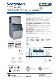
<strong>SCOTSMAN</strong> <strong>EUROPE</strong> <strong>SERVICE</strong> <strong>DEPARTMENT</strong><br />
SP-09.07 – APRIL ‘09<br />
MV 456-606-806-1006<br />
NEW PC BOARD & SENSORS<br />
KIT FOR VERY SOFT WATER<br />
A new PC Board & Sensors Kit, for the New MV ..6 Series machines, is now available<br />
as service part under Part Nbr CM 81454417.<br />
This new PC Board & Sensors Kit, that works in the same way of the current standard<br />
one, allows the correct operation of the MV ..6 Series even when water is very soft<br />
and/or de-mineralized, like the one produced by the Reverse Osmosis water treatment<br />
system.<br />
The major components of the new PC Board & Sensors Kit are:<br />
PC Board P/N CM 33580171<br />
Ice thickness sensor CM 81455066<br />
Ground cable CM 81453902<br />
Water level sensor cable CM 81454416<br />
The PC Board only is the same used on the current MV Series (MV 300 -> MV 1000)<br />
equipped with the Hi Sensitivity Board and is equipped with DIP Switches for the<br />
proper setting according to the model where installed as detailed on the last page of the<br />
attached Pure Water Board installation instructions.
PURE<br />
WATER<br />
BOARD<br />
71503782/0<br />
INSTALLATION KIT<br />
KIT DI INSTALLAZIONE<br />
PURE WATER BOARD<br />
SCHEDA PER ACQUA<br />
DEMINERALIZZATA<br />
WATER LEVEL SENSOR HARNESS<br />
CAVO DI COLLEGAMENTO SENSORE DI<br />
LIVELLO ACQUA ALLA SCHEDA<br />
GROUND CABLE<br />
CAVO DI TERRA<br />
NEW ICE SENSOR WITH HARNESS<br />
SENSORE GHIACCIO CON FILO DI COL-<br />
LEGAMENTO ALLA SCHEDA<br />
11/03/09
PURE<br />
WATER<br />
BOARD<br />
71503782/0<br />
INSTALL THE ICE SENSOR ON ITS<br />
BRACKET AND CONNECT TO THE BOARD<br />
(BOARD CONNECTOR “ICE SENSOR”)<br />
POSIZIONARE IL SENSORE GHACCIO SUL<br />
SUPPORTO E COLLEGARE IL FILO ALLA<br />
SCHEDA (CONNETTORE DELLA SCHEDA<br />
“ICE SENSOR”)<br />
REPLACE THE WATER LEVEL SENSOR<br />
HARNESS AND CONNECT IT TO THE<br />
BOARD (BOARD CONNECTOR “WATER<br />
LEV.”).<br />
SOSTITUIRE IL CAVO DEL SENSORE DI<br />
LIVELLO ACQUA E COLLEGARLO ALLA<br />
SCHEDA, (CONNETTORE DELLA SCHE-<br />
DA “WATER LEV.”).<br />
11/03/09
PURE<br />
WATER<br />
BOARD<br />
71503782/0<br />
REPLACE THE BOARD<br />
NOTE: THE BOARD CONNECTORS ARE<br />
THE SAME (EXCEPT ICE AND WATER<br />
LEVEL SENSOR CONNECTORS)<br />
THEN CONNECT THE GROUND CABLE<br />
TO THE BOARD (BOARD CONNECTOR<br />
“GND”) AND TO THE GROUND TERMINAL<br />
SOSTITUIRE LA SCHEDA<br />
NOTA: I CONNETTORI DELLA SCHEDA<br />
SONO GLI STESSI (ECCETTO I<br />
CONNETTORI DEI SENSORI GHACCIO E<br />
ACQUA)<br />
POI COLLEGARE IL CAVO DI TERRA ALLA<br />
SCHEDA (CONNETTORE DELLA SCHEDA<br />
“GND”) E AL MORSETTO DI TERRA<br />
ICE SENSOR CONNECTOR<br />
CONNETTORE SENSORE GHIACCIO<br />
WATER LEVEL SENSOR CONNECTOR<br />
CONNETTORE SENSORE DI LIVELLO<br />
ACQUA<br />
GROUND CONNECTOR<br />
CONNETTORE DI TERRA<br />
11/03/09
DIP SWITCH SELECTOR<br />
SELETTORE DIP SWITCH<br />
AUTOTEST JUMPER<br />
AUTOTEST ON: JUMPER IN<br />
AUTOTEST OFF: JUMPER OUT (STANDARD MODE)<br />
PONTICELLO PER FUNZIONE AUTOTEST<br />
AUTOTEST ON: PONTICELLO CHIUSO<br />
AUTOTEST OFF: PONTICELLO APERTO (FUNZIONAMENTO STANDARD)
<strong>SCOTSMAN</strong> <strong>EUROPE</strong> <strong>SERVICE</strong> <strong>DEPARTMENT</strong><br />
SP-09.08 – APRIL ‘09<br />
MV 456-606-806-1006<br />
WATER LEVEL SENSOR<br />
HARNESS<br />
We would like to inform you that under some very rare circumstances, the Water Level<br />
Sensor of the new MV ..6 series can switch off the water inlet valve with a very low<br />
level of water into the water reservoir (water level corresponding to the longer water<br />
sensor finger).<br />
This can happen when the Water Level Sensor Harness have the two wires connected on<br />
reverse and water is dripping onto the Ice Thickness Sensor at the beginning of the<br />
freezing cycle.<br />
If so, the signal transmitted to the PC Board through<br />
the Ice Thickness Sensor is equivalent to have the<br />
water reservoir full of water tripping OFF the water<br />
inlet solenoid valve.<br />
In this condition the machine operates into the freezing<br />
cycle with a very low level of water tripping OFF 40<br />
minutes later with the Red Alarm Led of the Too Long<br />
Harvest cycle ON.<br />
To overcome the problem the Water Level Sensor<br />
Harness must be replace with the correct one (see<br />
beside drawing and below photo) available under Part<br />
Nbr CM 81455102.
<strong>SCOTSMAN</strong> <strong>EUROPE</strong> <strong>SERVICE</strong> <strong>DEPARTMENT</strong><br />
SP-09.09 – MAY ‘09<br />
MF 36<br />
NEW PC BOARD FOR FIELD TEST<br />
On the MF 36 with the following serial numbers:<br />
From s.n. 18795 to s.n. 18816<br />
and<br />
From s.n. 18837 to s.n. 18900<br />
has been installed a new type of PC Board available under Part Nbr 620462 08 that<br />
consists of the standard PC Board used till new with the integration of the Cleaning<br />
Reminder Board – Not yet used.<br />
Moreover the compressor relay installed in this PC Board can load up to 16 amps<br />
current enabling the direct connection of the compressor to the PC Board even on bigger<br />
model (up to the MF 56 at 230/50/1).<br />
Attached you can find the schematic diagram of this new PC Board.<br />
As on the PC Board used on the most recent version of our AC Cubers, this new PC<br />
Board is equipped with a Push Button for the calibration of the Optical Ice Level<br />
Control that must be as per follow procedure:<br />
• Be sure that both Transmitter & Receiver of the Ice Level Control are properly<br />
clean and scale free<br />
• Switch OFF the machine at Power Line Master Switch<br />
• Push and Hold the PC Board Push Button<br />
• Switch ON the machine at Power Line Master Switch<br />
• Wait few seconds till the PC Board Leds flash once<br />
• Release the PC Board Push Button<br />
• Calibration is done<br />
Due to the different electrical connections, this new PC Board is NOT exchangeable<br />
with the former one used on the same models.<br />
Attached you can find the schematic diagram of the PC Board as well as the wiring<br />
diagram of the machine.
CUT OUT COND. TEMP.<br />
CUT OUT COND. TEMP.<br />
JUMP OUT – 60°C - WC<br />
JUMP OUT – 60°C - WC<br />
JUMP IN – 70°C - AC<br />
JUMP IN – 70°C - AC<br />
START UPDELAY TIME<br />
START UPDELAY TIME<br />
JUMP OUT – 60’ DELAY<br />
JUMP OUT – 60’ DELAY<br />
JUMP IN – 3’ DELAY<br />
JUMP IN – 3’ DELAY<br />
PUSH BUTTON<br />
PUSH BUTTON<br />
WATER SYSTEM<br />
WATER SYSTEM<br />
CLEANING REMIND –<br />
CLEANING REMIND –<br />
FUTURE USE<br />
FUTURE USE<br />
JUMP OUT - 12 MONTHS<br />
JUMP OUT - 12 MONTHS<br />
JUMP IN - 6 MONTHS<br />
JUMP IN - 6 MONTHS<br />
TEST<br />
TEST<br />
MICROPROCESSOR<br />
MICROPROCESSOR<br />
TRIAC<br />
TRIAC<br />
TRANSFORMER<br />
TRANSFORMER<br />
POWER<br />
POWER<br />
BIN FULL<br />
BIN FULL<br />
NO WATER<br />
NO WATER<br />
ALARM – START<br />
ALARM – START<br />
UP DELAY TIME<br />
UP DELAY TIME<br />
PRO-EL.IND.<br />
COMPRESSOR<br />
COMPRESSOR<br />
RELAY<br />
RELAY<br />
EXTERNAL SWICHES<br />
EXTERNAL SWICHES<br />
SOCKET-FUTURE USE<br />
SOCKET-FUTURE USE<br />
GEAR MOTOR<br />
GEAR MOTOR<br />
RELAY<br />
RELAY<br />
TO HI EVAP. TEMP.<br />
TO HI EVAP. TEMP.<br />
WRONG OR SLOW<br />
WRONG OR SLOW<br />
DRIVE MOTOR<br />
DRIVE MOTOR<br />
ROTATION<br />
ROTATION<br />
WATER LEVEL SENSOR<br />
WATER LEVEL SENSOR<br />
DRIVE MOTOR SENSOR<br />
DRIVE MOTOR SENSOR<br />
CONDENSER SENSOR<br />
CONDENSER SENSOR<br />
VARISTOR<br />
VARISTOR<br />
OPTICAL ICE LEVEL<br />
OPTICAL ICE LEVEL<br />
CONTROL SENSOR<br />
CONTROL SENSOR<br />
EVAPORATOR SENSOR<br />
EVAPORATOR SENSOR<br />
FUSE<br />
FUSE<br />
COMPRESSOR<br />
COMPRESSOR<br />
ELECTRICAL<br />
ELECTRICAL<br />
CONNECTIONS<br />
CONNECTIONS<br />
TERMINAL<br />
TERMINAL<br />
BOARD<br />
BOARD
SCK1
EV1<br />
Fan motor<br />
Ventilatore<br />
M1<br />
Compressor<br />
Compressore<br />
M3<br />
Drive Motor<br />
Motoriduttore<br />
OP1<br />
BIN full sensor<br />
Sensore contenitore pieno<br />
RT1<br />
Gear motor rotation sensor<br />
Sensore rotazione motoriduttore<br />
SA1<br />
Power switch<br />
Interruttore generale<br />
SB1<br />
Reset push button<br />
Pulsante di reset<br />
SCK1<br />
Printed circuit command board<br />
Scheda elettronica di comando<br />
WS1<br />
Water level control<br />
Controllo livello acqua<br />
TC1<br />
Condenser temperature sensor<br />
Sensore temperatura condensatore<br />
TC2<br />
Evaporator temperature sensor<br />
Sensore temperatura evaporatore
<strong>SCOTSMAN</strong> <strong>EUROPE</strong> <strong>SERVICE</strong> <strong>DEPARTMENT</strong><br />
SP-09.10 – MAY ‘09<br />
AC-EC 46-56-86<br />
NEW EVAPORATOR<br />
THERMOSTATS P/N 620264 11/16<br />
On the past weeks we have moved from Ranco to new Atea Thermostats due to<br />
availability problems we are having with the former supplier.<br />
The two thermostats, in the various settings/configurations, are perfectly exchangeable<br />
as they have the same numbers to identify the spade contacts as shown on the here<br />
below photos.<br />
2<br />
3<br />
6<br />
4<br />
Attached the AC/EC wiring diagram for any possible need.
<strong>SCOTSMAN</strong> <strong>EUROPE</strong> <strong>SERVICE</strong> <strong>DEPARTMENT</strong><br />
SP-09.11 – JUNE ‘09<br />
MAR SERIES – MF 86-88<br />
CORRECT SETTING OF TIME<br />
DELAY RANGE ADJUSTING SCREW<br />
We would like to point you up about the correct setting of the adjusting range screw<br />
used on both the Compressor and Drive Motor Time Delay Part Nbr. EQ DAA51CM<br />
fitted into all MAR units as well as on MF 86/88 control box.<br />
To correctly operate the small arrow of the Range screw MUST be placed in<br />
correspondence of the setting time; in this position, when the Time Delay is in<br />
operation, (start up and trip off of the machine) the small yellow led blinks slow (2<br />
blinks per second).<br />
At contrary, if it’s NOT placed in the correct position, it looks like the Time Delay is<br />
still in operation (yellow led blinks fast – 5 blinks per second) but it’s not through as it<br />
remains all the time in this position w/out energize the Compressor or the Drive Motor<br />
relay.<br />
Attached a chart that we are going to place in each machine in order to alert the<br />
installer.
CORRECT SETTING<br />
REGOLAZIONE CORRETTA<br />
SLOW BLINK<br />
LAMPEGGIO LENTO<br />
2 PER SECOND<br />
WRONG SETTING<br />
REGOLAZIONE ERRATA<br />
FAST BLINK<br />
LAMPEGGIO VELOCE<br />
5 PER SECOND<br />
OK<br />
NO<br />
CLICK<br />
NO<br />
CLICK
<strong>SCOTSMAN</strong> <strong>EUROPE</strong> <strong>SERVICE</strong> <strong>DEPARTMENT</strong><br />
SP-09.12 – JUNE ‘09<br />
MF 46-56-58-66-68 - MFN 46-56<br />
CHANGE ON AUGER BOTTOM<br />
SHAFT O RING<br />
Starting from the following serial nbrs:<br />
MF 46 S.N. 15939<br />
MF 56 23453<br />
MF 58 01647<br />
MF 66 05368<br />
MF 68 01614<br />
MFN 46 00027<br />
MFN 56 00032<br />
we have changed the size of the groove as well as of the O Ring fitted on the bottom<br />
shaft of the auger moving to a bigger one (2,62 mm in place of the current 1,78 mm<br />
chord diameter one, as shown on the here below photo)<br />
OLD<br />
NEW<br />
The larger chord assures an higher friction between the auger shaft and the inner ring of<br />
the bottom bearing so to avoid that the auger shaft can turn free inside the bottom<br />
bearing inner ring with the possibility to worn out the shaft.<br />
The new augers, available under the same part nbrs of the former ones, will be supplied<br />
completed with its larger O Ring and they are perfectly exchangeable with the previous<br />
ones.<br />
The New O Ring, P/N 640041 01 (the same of the one used on AF Ice Breaker) can<br />
NOT be installed on the old augers due to the different size of the groove.
The increase of the friction between the auger shaft and the bottom bearing inner ring may cause some problem in<br />
the withdrawing of the auger from the top of the worm tube/evaporator.<br />
To facilitate the rise up of the auger/ice breaker assy, it’s possible to use two of the four screws securing the ice<br />
breaker to the upper evaporator flange in combination with the two threaded holes using the ice breaker like an<br />
extractor as shown on the photos.<br />
As the auger is supplied with the O Ring pre-installed we suggest you, at time of installation of the upper portion of<br />
the water seal, to remove it in order to avoid any interference with the O Ring located into the S.S. ring as shown<br />
on the here below photos/procedure.<br />
1<br />
2<br />
FOOD<br />
GRADE<br />
GREASE<br />
3<br />
4
<strong>SCOTSMAN</strong> <strong>EUROPE</strong> <strong>SERVICE</strong> <strong>DEPARTMENT</strong><br />
SP-09.13 – SEPT ‘09<br />
TCL 180<br />
NEW DISPENSING VANE<br />
Starting from TCL 180 serial nbr 5435, the old dispensing vane with rectangular<br />
openings have been replaced with a new shorter one w/out any openings as shown on<br />
the here below photo.<br />
This to assure the best storage capacity as well as the correct dispensing of the ice even<br />
in case of “ice block formation” that can happen in some TCL 180’s where it’s not very<br />
frequent the request of the ice by end users.<br />
The new Dispensing Vane is available under Part Nbr 650882 12 and will be supplied<br />
since now in place of the former one Part Nbr 650882 10.
<strong>SCOTSMAN</strong> <strong>EUROPE</strong> <strong>SERVICE</strong> <strong>DEPARTMENT</strong><br />
SP-09.14 – SEPT ‘09<br />
TCS 180<br />
NEW LOCATION OF OPTICAL<br />
ICE LEVEL CONTROL<br />
On the past weeks we have received some field reports about the possible ice bridge<br />
formation over the Optical Ice Level Control used on TCS 180 that, in some<br />
circumstances it can arrive to move out the spout plastic cover with the possibility to<br />
have ice inside the machine.<br />
Test done in our lab proves it mainly when ice is not dispensed for hours (the vibrations<br />
due to the rotation of the dispending vane is more then enough to allow the ice bridge to<br />
fall down into the storage bin).<br />
To overcome the problem we have moved the Optical Ice Level Control inside the<br />
storage bin, as on the old TC 180 version, so to avoid any possible ice bridge formation.<br />
The change/improvement starts from TCS 180 s.n. 5445<br />
To up to date the TCS 180’s in the field we made available a Retrofit Kit at no charge<br />
under Part Nbr 060694 00 consisting off:<br />
• S.S. bracket<br />
• Holding screws, nuts & washers<br />
• Plastic covers for the Optical Ice Level Control eyes<br />
• Plastic plugs to close the holes on the storage bin cover<br />
as shown on the attached photos.
PLASTIC<br />
PLUG<br />
SCREWS<br />
& NUTS<br />
METAL<br />
BRACKET<br />
PLASTIC<br />
PROTECTIONS
ICE LEVEL<br />
CONTROL CABLE<br />
IN BETWEEN<br />
STORAGE BIN<br />
PLASTIC COVER<br />
AND STORAGE<br />
BIN WALL
<strong>SCOTSMAN</strong> <strong>EUROPE</strong> <strong>SERVICE</strong> <strong>DEPARTMENT</strong><br />
SP-09.15 – OCT ‘09<br />
P C BOARD PART NBR<br />
620462 06<br />
CALIBRATION OF THE<br />
OPTICAL ICE LEVEL CONTROL<br />
We would like to remind you, as written on the Instruction Sheet supply with the PC<br />
Board P/N 620462 06 (copy attached), that at time of the replacement of the PC Board<br />
or of the Optical Ice Level Control, it’s imperative to made the calibration of the two<br />
components as detailed here below:<br />
• Switch OFF the machine at Green Master Push Button Switch<br />
• Push and Hold the PC Board Push Button<br />
• Switch ON the machine at Green Master Push Button Switch<br />
• Wait few seconds till the PC Board Leds flash once<br />
• Release the PC Board Push Button<br />
• Calibration is done<br />
This procedure must be done at time of PC Board or Optical Ice Level Control<br />
replacement and also any time the machine is tripping OFF at Bin Full without any ice<br />
in between the Optical Infrared Eyes.
<strong>SCOTSMAN</strong> <strong>EUROPE</strong> <strong>SERVICE</strong> <strong>DEPARTMENT</strong><br />
SP-09.16 – OCT ‘09<br />
MV 456-606-806-1006<br />
ICE THICKNESS SENSOR<br />
Field reports detail us of some possible problems with the setting screw of the Ice<br />
Thickness Sensors used on the firsts MV ..6 series versions.<br />
The setting screw is not properly hold inside the threaded hole of the plastic bracket<br />
with the possibility that vibrations during the operation of the machine can turn it<br />
reducing its distance from the evaporator as well as the thickness of the ice produced.<br />
FOOD PROOF<br />
SILICONE<br />
In this case, the thickness of the ice can become so thin with problem in defrosting it<br />
during the harvest cycle with the machine tripping OFF at too long harvest cycle time.<br />
To overcome the problem we suggest you to remove the setting screw, put some food<br />
proof silicone into the threaded hole and screw it in again.<br />
Just a small quantity of silicone is more then enough to hold the setting screw avoiding<br />
any free rotation due to the vibrations of the machine.
<strong>SCOTSMAN</strong> <strong>EUROPE</strong> <strong>SERVICE</strong> <strong>DEPARTMENT</strong><br />
SP-09.17 – OCT ‘09<br />
MF 86 – MAR 205<br />
NEW VIBRATION ABSORBER<br />
ON DISCHARGE LINE<br />
Starting from the following serial nbr:<br />
MF 86 S.N. 00128<br />
MAR 205 02598<br />
the vibration absorber used till now has been replaced with a longer one (as shown on<br />
here below photo) so to reduce the vibrations transmitted by the compressor to the<br />
condenser.<br />
The part number of new vibration absorber is 650313 07 and it’s exchangeable with the<br />
former one.
<strong>SCOTSMAN</strong> <strong>EUROPE</strong> <strong>SERVICE</strong> <strong>DEPARTMENT</strong><br />
SP-09.18 – OCT ‘09<br />
MF 56-58-66-68<br />
NEW HIGHER BOTTOM<br />
BEARING<br />
Starting from the following serial numbers:<br />
MF 56 S.N. 23750<br />
MF 58 01691<br />
MF 66 05431<br />
MF 68 01674<br />
the bottom bearing of the freezer has been changed with a new taller one that can<br />
support 25% more radial load.<br />
In addition, the new bottom bearing has more room for the lubricant so to assure a<br />
longer life.<br />
To seat the new bottom bearing inside the worm tube we have been forced to modify the<br />
bottom bearing retainer as well as the aluminum adapter located under the worm tube.<br />
The new bottom bearing & retainer assy is available under P/N 060527 01 while the<br />
new modified aluminum adapter under P/N 764007 01.<br />
Due to these modifications the new bottom bearing & retainer assy Part Nbr 060527 01,<br />
is exchangeable with the former one only by exchanging it together with the new<br />
aluminum adaptor.<br />
For this reason is available a new kit under P/N 060688 00 consisting off:<br />
• New Brass housing<br />
• O rings<br />
• New Low bearing<br />
• New Aluminum adapter<br />
that will be supplied in place of the old bottom bearing & retainer P/N 060527 00 once<br />
we’ll run out of stock (for the moment the old bottom bearing & retainer is still used on<br />
MF 46).
The same modification/integration has been done on the Kit Bearings & Seals Part Nbr 001028 08.<br />
Under the Part Nbr 001028 08 is still available the Kit Bearing & Seal used till now (still valid for the model MF 46)<br />
while, under new Part Nbr 060692 00 is available the new one with taller bottom bearing and bearing retainer.<br />
A third Kit Bearing & Seal is made also available under Part Nbr 060692 01.<br />
It consists of the Kit Part Nbr 060692 00 with the addition of the new aluminum adapter P/N 764007 01 to be used in<br />
place of the Kit Part Nbr 001028 08 once we’ll run out of stock of the same.<br />
Here below a chart resuming the different part nbrs.<br />
Up to now<br />
Old machines<br />
From now on<br />
New machines<br />
New kit to be used<br />
in old machines<br />
It includes New<br />
Aluminum adapter<br />
Part Nbr 764007 01<br />
Bottom bearing & retainer 060527 00 060527 01 060688 00<br />
Kit Bearing & Seals 001028 08 060692 00 060692 01<br />
Aluminum Adapter 764007 00 764007 01 ******
<strong>SCOTSMAN</strong> <strong>EUROPE</strong> <strong>SERVICE</strong> <strong>DEPARTMENT</strong><br />
SP-09.19 – OCT ‘09<br />
MF 56-58-66-68<br />
MFN 56<br />
NEW HIGHER FREEZER UPPER<br />
& BOTTOM FLANGES<br />
Starting from the following serial numbers:<br />
MF 56 S.N. 23785<br />
MF 58 01695<br />
MF 66 05431<br />
MF 68 01674<br />
MFN 56 00042<br />
the upper and bottom S.S. flanges of the freezer have been changed with thicker ones<br />
(we move from 5 mm to 8 mm thickness as shown on the bottom photos) so to proper
assure the perpendicularity between the gear reducer top cover and the freezer and have the perfect alignment between<br />
the gear motor output shaft and the auger shaft.<br />
The new worm tube as well as the new freezer assembly are available under the same part nbrs of the former ones and<br />
they are perfectly exchangeable with them.<br />
From the same serial nbrs we have also relocate the outlet of the capillary tube from the suction line so to avoid any<br />
possible contact/friction with compressor or the left side panel of the machine as shown on the here below photo.
<strong>SCOTSMAN</strong> <strong>EUROPE</strong> <strong>SERVICE</strong> <strong>DEPARTMENT</strong><br />
SP-09.20 – NOV ‘09<br />
AF 20-30-80-100-200<br />
NEW BIN DOOR WITH<br />
SANITIZING BAG POUCH<br />
Starting from the following serial numbers:<br />
AF 20 S.N. 12571<br />
AF 30 09831<br />
AF 80 07266<br />
AF 100 27718<br />
AF 200 03703<br />
the bin door is now equipped, as on AC Series, with a pouch to hold the sanitizing bag<br />
as shown on the here below photo.<br />
The new bin doors, available under the following Part Nbrs:<br />
AF 80 P/N 660642 00<br />
AF 20-30-100-200<br />
781503 00R<br />
are perfectly exchangeable with the former ones and will be supplied in place of them<br />
once we’ll run out of stock.
<strong>SCOTSMAN</strong> <strong>EUROPE</strong> <strong>SERVICE</strong> <strong>DEPARTMENT</strong><br />
SP-09.21 – NOV ‘09<br />
MC 16 AT 230V 60HZ<br />
NEW FAN MOTOR ASSY<br />
Starting from the serial number 18286 the previous fan motor assy, used on both<br />
versions at 50/60Hz, has been replaced with a new more powerfull one on 60Hz only so<br />
to have a greater air flow and heat removal so to assure a better condensation mainly<br />
when machines are located in warm area.<br />
The new fan motor assy used ONLY on 230V 60Hz machines consists of:<br />
Fan motor P/N 620419 07<br />
Fan blade 620419 34<br />
Fan bracket 620419 65<br />
and it’s exchangeable with the former one only as set.
<strong>SCOTSMAN</strong> <strong>EUROPE</strong> <strong>SERVICE</strong> <strong>DEPARTMENT</strong><br />
SP-09.22 – NOV ‘09<br />
MAR 305<br />
NEW COMPRESSOR<br />
Starting from the serial number 01346 the previous Dorin Compressor (K1000CS, no<br />
longer manufactured by Dorin) has been replaced with a new one (Dorin H1000CS)<br />
available under the following part nbr:<br />
400/50/3 P/N 670104 02<br />
As the refrigerant service valves are located in different position, compared with the<br />
former one, the new compressor is not perfectly exchangeable with the previous one<br />
unless of partial modification of the copper tubes.
<strong>SCOTSMAN</strong> <strong>EUROPE</strong> <strong>SERVICE</strong> <strong>DEPARTMENT</strong><br />
SP-09.23 – NOV ‘09<br />
MF 26-36<br />
NEW WATER TUBE & FITTINGS<br />
Starting from the following serial number:<br />
MF 26 S.N. 04602<br />
MF 36 19608<br />
the entire water inlet tube/fittings has been redesigned moving from copper tube to John<br />
Guest quick connections and nylon tube.<br />
The new components are available under the following part nbrs:<br />
Water inlet plastic fitting P/N 660956 00<br />
1/4“ male fitting 651206 01<br />
1/4” OD nylon tube (sold per meter) 651206 02<br />
1/4” female – 5/16” female connector 651224 04<br />
1/4” female S.S. nozzle 723107 02<br />
as shown on the attached page.
660956 00<br />
651206 02<br />
651224 04<br />
651206 01<br />
723107 02<br />
651206 02
<strong>SCOTSMAN</strong> <strong>EUROPE</strong> <strong>SERVICE</strong> <strong>DEPARTMENT</strong><br />
SP-09.24 – DEC. ‘09<br />
AC SERIES PC BAORD<br />
PART NBR 620462 06<br />
NEW VERSION/RELEASE<br />
Since now it’s available a new version of the PC Board Part Nbr 620462 06 used on the<br />
most recent series of the AC models.<br />
The main differences, compared with the former one, are:<br />
At restart, after the trippiong OFF at Bin Full, the new PC Board made 45<br />
seconds water filling phase so to refill the water sump up to the maximum level<br />
In case of malfunction of the Optical Ice Level Control, the new PC Board<br />
switch ON alternativelt the Yellow and Red Led continuously<br />
This new version, perfectly exchangeable with the former one, will be soon installed on<br />
the AC Series once we’ll run out of stock of previous version.<br />
Dip Switches setting is as per former version while the four jumpers must be set up as<br />
below:<br />
WATER SYSTEM CLEANING REMIND<br />
JUMP IN - 6 MONTHS<br />
JUMP OUT - 12 MONTHS<br />
RAPPEL NETTOYAGE SYSTEME<br />
HYDRAULIQUE<br />
CONTACT FERME’ - 6 MOIS<br />
CONTACT OUVERTE - 12 MOIS<br />
RICHIAMO PULIZIA SISTEMA IDRICO<br />
CONTATTO CHIUSO - 6 MESI<br />
CONTATTO APERTO - 12 MESI<br />
TEST<br />
AC/EC MODELS<br />
JUMP IN – AC SERIES<br />
JUMP OUT - EC SERIES<br />
MODELES AC/EC<br />
CONTACT FERME’ - SERIES AC<br />
CONTACT OUVERTE - SERIES EC<br />
MODELLI AC/EC<br />
CONTATTO CHIUSO - SERIE AC<br />
CONTATTO APERTO - SERIE EC<br />
START UP DELAY<br />
JUMP IN - 0 MIN.<br />
JUMP OUT - 60 MIN.<br />
RETARD AU DEMARRAGE<br />
CONTACT FERME’ - 0 MIN<br />
CONTACT OUVERTE - 60 MIN<br />
RITARDO ALLA PARTENZA<br />
CONTATTO CHIUSO - 0 MIN<br />
CONTATTO APERTO - 60 MIN.<br />
Attached two resuming charts showing leds meanings and differences between the<br />
various versions of PC Boards.
PC BOARD 620462 06 – NEW RELEASE – NUOVELLE VERSION – NUOVA VERSIONE<br />
LED STATUS REASON WHY-SIGNIFICATION-SIGNIFICATO<br />
ON STEADY<br />
FIXE<br />
FISSO<br />
UNIT UNDER POWER<br />
SOUS TENSION<br />
IN TENSIONE<br />
ON STEADY<br />
FIXE<br />
FISSO<br />
BLINKING<br />
CLIGNOTANT<br />
LAMPEGGIANTE<br />
ON STEADY<br />
FIXE<br />
FISSO<br />
BLINKING<br />
CLIGNOTANT<br />
LAMPEGGIANTE<br />
ON STEADY<br />
FIXE<br />
FISSO<br />
BLINKING SLOW<br />
CLIGNOTANT LENT<br />
LAMPEGGIANTE LENTO<br />
BLINKING FAST<br />
CLIGNOTANT RAPIDE<br />
LAMPEGGIANTE VELOCE<br />
ON STEADY<br />
FIXE<br />
FISSO<br />
BLINKING<br />
CLIGNOTANT<br />
LAMPEGGIANTE<br />
ON STEADY<br />
FIXE<br />
FISSO<br />
BLINKING<br />
CLIGNOTANT<br />
LAMPEGGIANTE<br />
BLINKING ALTERNATIVELY<br />
CLIGNOTANT ALTERNE’<br />
LAMPEGGIO ALTERNATO<br />
FREEZING CYCLE<br />
EN RÉFRIGÉRATION<br />
IN CONGELAMENTO<br />
60 MINUTES DELAY AT START UP – JUMPER J3 OUT<br />
60 MINUTES DE RETARD AU DEMARRAGE – CAVALIER J3 OUVERTE<br />
60 MINUTI RITARDO PARTENZA – CONTATTI J3 APERTI<br />
TOO HI DISCHARGE PRESSURE/TEMP<br />
COUPURE HP<br />
FERMATA ALTA TEMP. CONDENSAZIONE<br />
TOO HI EVAP. TEMP. (> 0C°) AFTER 15' FROM START UP<br />
COUPURE BP (0°C LU PAR LA SONE EVAP, NON ATTEINTE APRES 15' FONCT.)<br />
TEMP. EVAP >0 °C DOPO 15' DA INIZIO CONGELAMENTO<br />
UNIT OFF AT BIN FULL<br />
CABINE PLEINE<br />
CONTENITORE PIENO<br />
I/R BEAM CUTTED<br />
FAISCEAU INFRA ROUGE CELLULE NIVEAU GLACE INTERROMPU<br />
RAGGIO INFRAROSSO INTERROTTO<br />
I/R ON AFTER TRIP OFF AT BIN FULL<br />
FAISCEAU INFRA ROUGE CELLULE NIVEAU GLACE ETABLI<br />
RAGGIO INFRAROSSO RIPRISTINATO DOPO FERMATA A CONT. PIENO<br />
I/R CALIBRATION DONE<br />
CALIBRATION FAISCEAU INFRA ROUGE CELL. NIVEAU GLACE REALISE’<br />
CALIBRAZIONE RAGGIO INFRAROSSO EFFETTUATA<br />
UNIT IN CLEANING MODE OR TRIPPING OFF AFTER TEST – JUMPER TEST IN<br />
MACHINE EN MODE DETARTRAGE OU ARRETE APRES LE TEST – CAVALIER TEST FERME’<br />
MACCHINA NELLA FASE LAVAGGIO O FERMA DOPO IL TEST – PONTICELLO TEST CHIUSO<br />
CONDENSER SENSOR OUT OF ORDER<br />
SONDE CONDENSEUR HS<br />
SONDA CONDENSATORE MALFUNZIONANTE<br />
EVAPORATOR SENSOR OUT OF ORDER<br />
SONDE EVAPORATEUR HS<br />
SONDA EVAPORATORE MALFUNZIONANTE<br />
I/R SENSOR OUT OF ORDER<br />
SONDE INFRA ROUGE CELLULE NIVEAU GLACE HS<br />
SONDA ALL’INFRAROSSO LIVELLO GHIACCIO MALFUNZIONANTE<br />
PUSH<br />
PUSH > 5" DURING WATER FILLING TO MOVE THE UNIT INTO FREEZING<br />
PUSH > 5" DURING FREEZING TO MOVE THE UNIT INTO DEFROST<br />
PUSH > 5" DURING DEFROST TO MOVE THE UNIT INTO FREEZING<br />
PUSH 2" < 5" DURING WATER FILLING TO MOVE THE UNIT INTO CLEANING<br />
PUSH DURING THE 60 MIN START UP DELAY TIME TO BY-PASS IT<br />
APPUI > 5" EN REMPLISSAGE POUR BASCULER LA MACHINE EN REFRIGERATION<br />
APPUI > 5" EN CONGELATION POUR BASCULER LA MACHINE EN DEGIVRAGE<br />
APPUI > 5" EN DEGIVRAGE POUR BASCULER LA MACHINE EN CONGELATION<br />
APPUI 2"< 5" EN REMPLISSAGE POUR BASCULER LA MACHINE EN DETARTRAGE<br />
APPUI PENDANT LE RETARD AU DEMARRAGE POUR LE BY-PASSER<br />
PREMERE > 5" DURANTE CARICAMENTO ACQUA PER METTERE LA MACCHINA IN CONGELAMENTO<br />
PREMERE > 5" DURANTE CONGELAMENTO PER METTERE LA MACCHINA IN SBRINAMENTO<br />
PREMERE > 5" DURANTE SBRINAMENTO PER METTERE LA MACCHINA IN CONGELAMENTO<br />
PREMERE 2" < 5" DURANTE CARICAMENTO ACQUA PER METTERE LA MACCHINA IN LAVAGGIO<br />
PREMERE DURANTE IL RITARDO ALLA PARTENZA PER BY-PASSARLO
PC BOARD - CARTE ELECTRONIQUE<br />
SCHEDA ELETTRONICA - STEUERKARTE<br />
SYEN<br />
CALIBRATION OF THE I/R ICE LEVEL<br />
CONTROL<br />
At time of installation it's necessary to perform the<br />
calibration of the I/R Ice Level control.<br />
• Switch OFF the machine at Master Green<br />
Push Button Switch<br />
• Push and hold the PC Board Push Button<br />
• Switch ON the machine at Master Green Push<br />
Button Switch<br />
• Few seconds later the LEDs of the PC Board<br />
starts to blink<br />
• Release the PC Board Push Button<br />
The I/R Ice Level control is now calibrate<br />
ETALONNAGE DE LA CELLULE INFRAROUGE<br />
Lors de l'installation de la carte électronique, il est<br />
nécessaire de faire l'étalonnage de la cellule<br />
infrarouge<br />
• Arrêter la machine à l'aide du bouton poussoir<br />
vert extérieur de la machine.<br />
• Pousser le bouton de la carte et le maintenir<br />
enfoncé.<br />
• Mettre en marche la machine à l'aide de<br />
bouton poussoir vert extérieur.<br />
• Apres 6-7 secondes les LEDs de la Carte<br />
commence à clignoter<br />
• Relâcher le bouton poussoir de la carte<br />
La cellule infrarouge est étalonnée.<br />
CALIBRAZIONE DELLA SONDA OTTICA<br />
All'installazione della scheda elettronica è<br />
necessario fare la calibrazione della sonda<br />
all'infrarosso<br />
• Spegnere la macchine all'interruttore a<br />
pulsante verde<br />
• Premere il punsante della scheda elettronica<br />
• Mantenendo premuto il pulsante della scheda<br />
elettronica, mettere in marca la macchina<br />
all'interruttore verde<br />
• Dopo pochi secondo i tre LED della scheda<br />
iniziano a lampeggiare<br />
• Rilasciare il pulsante della scheda elettronica<br />
La sonda all'infrarosso è calibrata.<br />
KALIBRIERUNG DER EISNIVEAU<br />
IR – LICHTSCHRANKE<br />
Bei der Installation ist es notwendig eine<br />
Kalibrierung für die IR – Lichtschranke<br />
durchzuführen<br />
• Schalten Sie die Maschine am grünen<br />
Hauptschalter aus<br />
• Drücken und halten Sie den Taster auf<br />
der Platine<br />
• Schalten Sie die Maschine bei<br />
gedrücktem Taster wieder ein<br />
• Halten Sie den Taster solange gedrückt<br />
bis die LED auf der Platine blinkt<br />
Die IR – Lichtschranke ist nun kalibriert
PC BOARD P/N 620462 06 - DIP SWITCH FACTORY SETTINGS<br />
SMALL CUBES<br />
MEDIUM CUBES<br />
LARGE CUBES<br />
DEFR. CYCLE ADD.<br />
AIR<br />
FREEZING CYCLE<br />
DEFROST CYCLE<br />
15/30"<br />
DIP SWITCH<br />
TIME<br />
WATER<br />
1 2 3 4 5 6 7 8 9 10<br />
ACS/ECS 126-176 A ON ON OFF ON OFF ON ON ON OFF ON<br />
ACS 226/ECS 226 A OFF OFF ON ON ON OFF ON ON ON ON<br />
ACS 226/ECS 226 W OFF OFF ON ON ON OFF ON ON ON OFF<br />
MCS 8 A ON ON ON ON OFF ON ON ON ON ON<br />
MCS 8 W ON ON ON ON OFF ON ON ON ON OFF<br />
ACM/ECM 106 A ON ON OFF ON ON OFF ON ON OFF ON<br />
ACM/ECM 106 W ON ON OFF ON ON OFF ON ON OFF OFF<br />
ACM/ECM 126 A ON ON OFF ON ON OFF ON ON OFF ON<br />
ACM/ECM 126-176 W ON ON OFF ON ON OFF ON ON OFF OFF<br />
ACM/ECM 176 A ON ON OFF ON OFF ON ON ON OFF ON<br />
ACM/ECM 206 A ON ON OFF ON OFF ON ON ON ON ON<br />
ACM 226/ECM 226 A ON ON OFF ON ON OFF ON ON ON ON<br />
ACM 226/ECM 226 W ON ON OFF ON ON OFF ON ON ON OFF<br />
MCM 8 A ON ON OFF ON OFF ON ON ON ON ON<br />
MCM 8 W OFF OFF ON ON ON OFF ON ON ON OFF<br />
ACL/ECL 106 A OFF OFF OFF ON OFF ON ON ON OFF ON<br />
ACL/ECL 106 W OFF OFF OFF ON OFF ON ON ON OFF OFF<br />
ACL/ECL 126 A ON ON ON OFF OFF ON OFF ON OFF ON<br />
ACL/ECL 126 W ON ON ON OFF OFF ON OFF ON OFF OFF<br />
ACL/ECL 176 A OFF OFF OFF ON OFF ON ON ON OFF ON<br />
ACL/ECL 176 W OFF OFF OFF ON OFF ON ON ON OFF OFF<br />
ACL 226/ECL 226 A OFF OFF OFF ON ON OFF ON ON ON ON<br />
ACL 226/ECL 226 W OFF OFF OFF ON ON OFF ON ON ON OFF<br />
MCL 8 A OFF OFF OFF ON OFF ON ON ON ON ON<br />
MCL 8 W OFF OFF OFF ON OFF ON ON ON ON OFF<br />
WATER SYSTEM CLEANING REMIND<br />
JUMP IN - 6 MONTHS<br />
JUMP OUT - 12 MONTHS<br />
RAPPEL NETTOYAGE SYSTEME<br />
HYDRAULIQUE<br />
CONTACT FERME’ - 6 MOIS<br />
CONTACT OUVERTE - 12 MOIS<br />
RICHIAMO PULIZIA SISTEMA IDRICO<br />
CONTATTO CHIUSO - 6 MESI<br />
CONTATTO APERTO - 12 MESI<br />
TEST<br />
AC/EC MODELS<br />
JUMP IN – AC SERIES<br />
JUMP OUT - EC SERIES<br />
MODELES AC/EC<br />
CONTACT FERME’ - SERIES AC<br />
CONTACT OUVERTE - SERIES EC<br />
MODELLI AC/EC<br />
CONTATTO CHIUSO - SERIE AC<br />
CONTATTO APERTO - SERIE EC<br />
START UP DELAY<br />
JUMP IN - 0 MIN.<br />
JUMP OUT - 60 MIN.<br />
RETARD AU DEMARRAGE<br />
CONTACT FERME’ - 0 MIN<br />
CONTACT OUVERTE - 60 MIN<br />
RITARDO ALLA PARTENZA<br />
CONTATTO CHIUSO - 0 MIN<br />
CONTATTO APERTO - 60 MIN.
<strong>SCOTSMAN</strong> <strong>EUROPE</strong> <strong>SERVICE</strong> <strong>DEPARTMENT</strong><br />
SP-09.25 – DEC. ‘09<br />
MV-MVP 456-606<br />
NEW HARVEST ASSIST SOLENOID<br />
Starting from the following serial numbers:<br />
MV 456 S.N. 00456<br />
MVP 456 00492<br />
MV 606 00543<br />
MVP 606 00583<br />
the former Harvest Assist Solenoid P/N 12002918 22 has been replaced with a new one<br />
with the plunger completely separated from the main solenoid body, as shown on the<br />
here below photos, so to avoid any possible friction between the plunger shaft and the<br />
hole of the evaporator and have it moving freely into the hole.<br />
The new Harvest Assist Solenoid, available under Part Nbr CM 19270501, is perfectly<br />
exchangeable with the former one.<br />
The same modification will be done shortly on the other MV-MVP models.<br />
Attached the simplest and fastest procedure to replace it.
Unloose and remove the<br />
two screws securing the<br />
havest assist bracket to<br />
the back side of the<br />
evaporator compartment<br />
Unloose and remove the<br />
four screws securing the<br />
harvest assist solenoid to<br />
its left side bracket and<br />
remove it from the<br />
machine<br />
Unloose and remove the<br />
four screws securing the<br />
right side bracket to the<br />
harvest assist solenoid<br />
and take it out<br />
To re-assembly follow the<br />
procedure on reverse
<strong>SCOTSMAN</strong> <strong>EUROPE</strong> <strong>SERVICE</strong> <strong>DEPARTMENT</strong><br />
SP-09.26 – DEC. ‘09<br />
MV 806 -1006<br />
NEW HARVEST ASSIST SOLENOID<br />
As done already few weeks ago with the smallest models of the MV series, starting<br />
from the following serial numbers:<br />
MV 806 S.N. 00077<br />
MV 1006 00042<br />
the former Harvest Assist Solenoid P/N 12002934 22 has been replaced with a new one<br />
with the plunger completely separated from the main solenoid body, as shown on the<br />
here below photos, so to avoid any possible friction between the plunger shaft and the<br />
hole of the evaporator.<br />
The new Harvest Assist Solenoid, available under Part Nbr CM 19270502, is perfectly<br />
exchangeable with the former one.