Network Camera FLC-1301, FXC-1302 - Eneo
Network Camera FLC-1301, FXC-1302 - Eneo
Network Camera FLC-1301, FXC-1302 - Eneo

You also want an ePaper? Increase the reach of your titles
YUMPU automatically turns print PDFs into web optimized ePapers that Google loves.
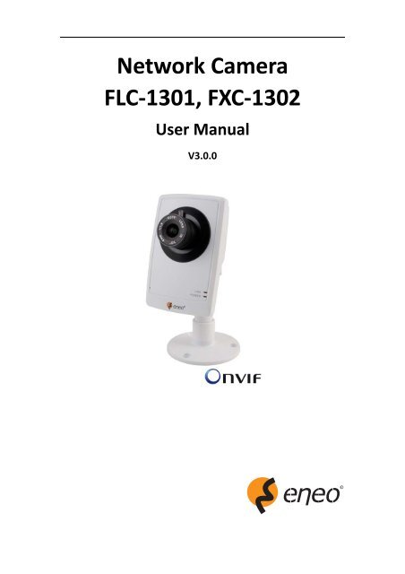
<strong>Network</strong> <strong>Camera</strong><br />
<strong>FLC</strong>‐<strong>1301</strong>, <strong>FXC</strong>‐<strong>1302</strong><br />
User Manual<br />
V3.0.0
User Manual of <strong>Network</strong> <strong>Camera</strong><br />
1
User Manual of <strong>Network</strong> <strong>Camera</strong><br />
2<br />
Safety Instructions<br />
• Read these safety instructions and the operation manual first before you install and commission<br />
the camera.<br />
• Keep the manual in a safe place for later reference.<br />
• Protect your camera from contamination with water and humidity to prevent it from permanent<br />
damage.<br />
Never switch the camera on when it gets wet. Have it checked at an authorized service center in<br />
this case.<br />
• Never operate the camera outside of the specifications as this may prevent the camera<br />
functioning.<br />
• Do not operate the cameras beyond their specified temperature, humidity or power ratings.<br />
Operate the camera only at a temperature range of ‐10°C to +50°C and at a humidity of max. 90%.<br />
• To disconnect the power cord of the unit, pull it out by the plug. Never pull the cord itself.<br />
• Pay attention when laying the connection cable and observe that the cable is not subject to heavy<br />
loads, kinks, or damage and no moisture can get in.<br />
• The warranty becomes void if repairs are undertaken by unauthorized persons.<br />
Do not open the camera housing.<br />
• Never point the camera towards the sun with the aperture open. This can destroy the sensor.<br />
• Installation, maintenance and repair have to be carried out only by authorized service centers.<br />
Before opening the cover disconnect the unit from mains input.<br />
• The fitter is responsible for the system of protection being followed in accordance with the<br />
technical data, e.g. by sealing of the cable outlet with silicone.<br />
• Contact your local dealer in case of malfunction.<br />
• Only use original parts and original accessories from Videor E. Hartig GmbH.<br />
• Do not use strong or abrasive detergents when cleaning the dome. Use a dry cloth to clean the<br />
dome surface.<br />
In case the dirt is hard to remove, use a mild detergent and wipe gently.<br />
• During assembly, care must be taken to ensure that existing seals are correctly inserted and are<br />
not displaced as a result of assembly.<br />
You must not continue to use damaged seals.
User Manual of <strong>Network</strong> <strong>Camera</strong><br />
3<br />
NOTE:<br />
This is a class A digital device. This digital device can cause harmful interference in a<br />
residential area;<br />
in this case the user may be required to take appropriate corrective action at his/her<br />
own expense.
User Manual of <strong>Network</strong> <strong>Camera</strong><br />
4<br />
Table of Contents<br />
Chapter 1 Introduction...........................................................................................................................1<br />
1.1 <strong>Network</strong> camera Functions and Features .................................................................................1<br />
1.2 Applications...............................................................................................................................1<br />
1.3 Package Contents ......................................................................................................................2<br />
Chapter 2 Installation.............................................................................................................................3<br />
2.1 <strong>Camera</strong> Description...................................................................................................................3<br />
2.1.1 <strong>Camera</strong> Physical Description...........................................................................................3<br />
2.1.3 <strong>Camera</strong> Connection.........................................................................................................4<br />
2.2 Hardware Installation................................................................................................................5<br />
Chapter 3 <strong>Network</strong> <strong>Camera</strong> Connection................................................................................................7<br />
Chapter 4 <strong>Network</strong> Access .....................................................................................................................9<br />
4.1 Access over IE Browser..............................................................................................................9<br />
4.1.1 Live View.......................................................................................................................10<br />
4.1.2 Parameters Configuration .............................................................................................12<br />
4.2 Access over Client Software....................................................................................................23<br />
4.2.1 Client Software Installation...........................................................................................23<br />
4.2.2 Live View.......................................................................................................................25<br />
4.2.3 <strong>Camera</strong> Parameters Configuration................................................................................29<br />
Chapter 5 Access over Internet............................................................................................................32<br />
5.1 Access network camera with static IP..............................................................................32<br />
5.2 Access network camera with dynamic IP.........................................................................33<br />
Chapter 6 Specifications and Drawings................................................................................................37<br />
6.1 Specifications ...................................................................................................................37<br />
6.2 Dimensional Drawings .....................................................................................................39<br />
Appendix 1 SADP Introduction.............................................................................................................40<br />
Appendix 2 Port Map ...........................................................................................................................42<br />
Appendix 3 Pin Definition ....................................................................................................................44
User Manual of <strong>Network</strong> <strong>Camera</strong><br />
1<br />
Chapter 1 Introduction<br />
<strong>Network</strong> camera is a kind of embedded digital surveillance product that combines the features<br />
of both traditional analog camera and network DVS (Digital Video Server). Due to the embedded<br />
Linux operation system and the latest Davinci hardware platform of TI, the system operates with<br />
high scheduling efficiency. Furthermore, the firmware is burned in the flash, which makes the<br />
product small, reliable and highly stable.<br />
1.1 <strong>Network</strong> camera Functions and Features<br />
Functions:<br />
<strong>Network</strong> Function: Support the TCP/IP protocols and IE browsing.<br />
Heartbeat Function: The server can acquire real time operating performance of the network<br />
camera through the heartbeat function.<br />
Alarm Function: Supports Motion Detection, Storage exception.<br />
User Management: Support multilevel right management. The administrator can create up to<br />
15 separate users with different right levels, which highly improves the system security.<br />
Compression Functions:<br />
Support 1 channel video signal and standard H.264 encoding compression, which supports both<br />
variable bit rate and variable frame rate; besides, you can self‐define both the video quality and<br />
its compressed bit rate.<br />
Remote Control:<br />
The product offers a 10M/100M self‐adaptive Ethernet interface.<br />
Support TCP/IP, HTTP, DHCP, DNS, DDNS, RTP/RTSP, PPPoE, SMTP, NTP protocols.<br />
Set the parameters, browse real time videos or check the camera performance by software or<br />
IE, and store the compressed bit rate through network.<br />
Support remote upgrades and maintenance.<br />
1.2 Applications<br />
This camera is ideal for remote control network applications. E.g.:<br />
1. <strong>Network</strong> surveillance for supermarkets and factories.<br />
2. Remote surveillance for homes and offices.<br />
3. Indoor monitoring scenes, such as hotel, corridor, stairway.
User Manual of <strong>Network</strong> <strong>Camera</strong><br />
2<br />
1.3 Package Contents<br />
1. <strong>Camera</strong> × 1<br />
2. Bracket × 1<br />
3. User Manual × 1<br />
4. Quick Start Guide × 1<br />
5. Installation Guide × 1<br />
6. CD × 1
User Manual of <strong>Network</strong> <strong>Camera</strong><br />
3<br />
Chapter 2 Installation<br />
NOTE:<br />
1. Please check if all the items on the package list have been included with your camera.<br />
2. Read the following contents carefully before the installation.<br />
3. Make sure that all the related equipment is power‐off during the installation.<br />
4. Check the power supply to prevent any damage caused by mismatching problems.<br />
5. If the product does not operate properly, please contact your dealer or the nearest service<br />
center. Never attempt to disassemble the camera yourself. Users are responsible for any<br />
problem caused by modification or repairing without authorization.<br />
2.1 <strong>Camera</strong> Description<br />
2.1.1 <strong>Camera</strong> Physical Description
User Manual of <strong>Network</strong> <strong>Camera</strong><br />
4<br />
Serial NO. Description<br />
1 Microphone hole<br />
2 Micro SD card solt<br />
3 LINK: <strong>Network</strong> status LED indicator.<br />
When the network is connected, the LED flickers in green.<br />
4 Power LED indicator, which turns red when power is applied to the unit<br />
5 Lens<br />
6 ETHERNET: 10M / 100M self‐adaptive Ethernet interface<br />
7 RESET: Reset all parameters to factory default settings<br />
8 Speaker hole<br />
9 Power supply<br />
10 Bracket mounting holes, used to fix the camera to the bracket<br />
NOTE:<br />
When the camera is power up, press the ‘RESET’ button for about 10 seconds, then all parameters,<br />
including user name, password, IP address, port number, etc., will be reset to the factory default<br />
settings.<br />
2.1.3 <strong>Camera</strong> Connection<br />
Step1:<br />
Connect one end of the network<br />
cable to the camera and the other<br />
end to PC.<br />
Step2:<br />
Connect one end of the power cord<br />
to the camera and the other end to<br />
power sokcket to supply power for<br />
the camera.<br />
Step3:<br />
Access the camera over IE or client<br />
software to view live video images.
User Manual of <strong>Network</strong> <strong>Camera</strong><br />
5<br />
2.2 Hardware Installation<br />
Cube camera can be fixed in both wall and ceiling, customers can choose diffierent ways to install<br />
the camera according to their specific needs. The following section introduces the ceiling mounting,<br />
and the wall mounting follows the same way:<br />
Step 1: Fix the camera mounting bracket to the ceiling.<br />
Fig 2.2.1 Fix camera mounting bracket<br />
NOTE:<br />
If it is wall, you need to fix the expand bolt (note: the mounting hole of the expand bolt should align<br />
with the bracket) before fixing the bracket as in Fig 2.2.1 . If the wall surface is wooden, the part of<br />
in Fig 2.2.1 can be ignored and you can use the self‐tapping screw to directly fix the bracket.<br />
Please note that the wall on which the camera is fixed should be able to bear at least three times<br />
the weight of the bracket and the camera.
User Manual of <strong>Network</strong> <strong>Camera</strong><br />
6<br />
Step 2: Screw the mounting hole to the mounting bracket, and then adjust the camera to the<br />
desired monitoring location and finally tighten the knob on bracket to secure the camera to the<br />
ceiling.<br />
Fig 2.2.2 Fix the <strong>Camera</strong><br />
Step 3: Viewing the video on the computer, if the scene is not that you want to monitor, loosen the<br />
knob on the mounting bracket and adjust the camera lens to the desired monitoring scene, and<br />
finally tighten the knob on bracket.<br />
Fig 2.2.3 Done
User Manual of <strong>Network</strong> <strong>Camera</strong><br />
7<br />
Chapter 3 <strong>Network</strong> <strong>Camera</strong> Connection<br />
Two methods can be used to connect between network camera and PC, shown as below:<br />
Fig. 3.1 Cross Line Connection<br />
Fig. 3.2 Direct Line Connection<br />
Before visiting network camera over network, user should acquire its IP address first. SADP is a<br />
software tool which can automatically detect network device in the LAN and give the device’s<br />
information like IP address, mask, port number, device serial number, software version, etc., shown<br />
as Fig. 3.3.
User Manual of <strong>Network</strong> <strong>Camera</strong><br />
8<br />
Fig. 3.3<br />
Select the device, and set its IP address and mask at the same network segment with the PC.<br />
For the detailed introduction of SADP, please refer to Appendix 1.<br />
Note: The network camera is set with the factory default IP address of “192.0.0.64”, the port of<br />
“8000”, the super user name of “admin” and the password of “12345”.
User Manual of <strong>Network</strong> <strong>Camera</strong><br />
9<br />
Chapter 4 <strong>Network</strong> Access<br />
After hardware installation, user can view live video and configure parameters for the network<br />
camera, including IP address, subnet mask and port number, etc. The following two methods can be<br />
used to access the camera:<br />
1. View live video and configure parameters over IE browser.<br />
2. View live video and configure parameters over client software.<br />
4.1 Access over IE Browser<br />
Before access to the camera over IE<br />
browser, user should adjust the security<br />
level.<br />
Open the IE browser, and set the<br />
security level to Medium in Tools/<br />
InternetOptions/Security/Custom<br />
Level..., and enable or prompt Activex<br />
Control and Plug‐in directly as well.<br />
Fig. 4.1.1 Adjust the Security Level
User Manual of <strong>Network</strong> <strong>Camera</strong><br />
10<br />
4.1.1 Live View<br />
Step 1: Install Active‐X Control<br />
Type the IP address of the network<br />
camera and press Enter, then the<br />
ActiveX mention dialog will pop<br />
up.<br />
Click Install to install the ActiveX<br />
control.<br />
Fig. 4.1.2 Install the ActiveX Control<br />
Step 2:<br />
Input the Username (default:<br />
admin), Password (default: 12345)<br />
and Port (default: 8000) of the<br />
camera, and then click [Login].<br />
Fig. 4.1.3 Login Interface
User Manual of <strong>Network</strong> <strong>Camera</strong><br />
11<br />
Step 3:<br />
After successful login, user is allowed to view the live video. Refer to Figure 4.1.4.<br />
Fig. 4.1.4 Live View Page<br />
Icons on Live View Page:<br />
Icon<br />
Description<br />
Full‐screen display mode<br />
Exit full‐screen display mode<br />
Start Preview<br />
Stop Preview<br />
Capture Picture<br />
Start/Stop Record<br />
Digital Zoom<br />
Video Parameters
User Manual of <strong>Network</strong> <strong>Camera</strong><br />
12<br />
Digital Zoom:<br />
Click mouse in the desired position of live video image and scroll the mouse to realize zoom in and<br />
zoom out function.<br />
Video Parameters:<br />
Icon<br />
Description<br />
Brightness: 0~100 configurable<br />
Contrast: 0~100 configurable<br />
Saturation: 0~100 configurable<br />
Hue: 0~100 configurable<br />
Gain: 0~100 configurable<br />
Exposure time: 0~40000<br />
configurable<br />
Restore default<br />
Fig. 4.1.5 Video Parameters<br />
4.1.2 Parameters Configuration<br />
Click Configuration to enter the Parameters Configuration interface.<br />
4.1.2.1 Local Configuration<br />
Fig. 4.1.6 Local Configuration
User Manual of <strong>Network</strong> <strong>Camera</strong><br />
13<br />
Local Configuration:<br />
Parameters<br />
Protocol type<br />
Stream type<br />
Display mode<br />
Package file size<br />
Transmission<br />
performance<br />
Save record file as<br />
Save captured<br />
picture as<br />
Description<br />
TCP and UTP selectable<br />
Main stream and Sub stream selectable<br />
Full‐screen, 4:3 mode, 16:9 mode or adjustable to resolution<br />
128M, 256M, 512M selectable<br />
Shortest delay mode, good real‐time, normal real‐time and fluency<br />
and good fluency options selectable<br />
The default directory for saving record files is C: \OCXRecordFiles,<br />
which can be modified by user<br />
The default directory for saving captured files is<br />
C:\OCXBMPCaptureFiles, which can be modified by user<br />
4.1.2.2 Remote Configuration<br />
Basic Information:<br />
In the Basic Information<br />
settings interface, user is<br />
allowed to set the Device<br />
Name and Device ID, as well as<br />
view the information of IP<br />
camera, including Device<br />
Description, Device Location,<br />
MAC address, Device Type,<br />
Device SN, Firmware Version,<br />
and U‐boot Version.<br />
Fig. 4.1.7 Basic Information
User Manual of <strong>Network</strong> <strong>Camera</strong><br />
14<br />
Channel Parameters Display<br />
Setting:<br />
According to different<br />
requirements, enable the<br />
display of Date&Time and<br />
Week by clicking the checkbox.<br />
Different date formats can be<br />
selected.<br />
The OSD Status can be set to<br />
transparent & flickering,<br />
transparent & unflickering,<br />
nontransparent & flickering, or<br />
nontransparent & unflickering.<br />
Fig. 4.1.8 Display Settings<br />
Channel Parameters Video Settings:<br />
Fig. 4.1.9 Video Settings
User Manual of <strong>Network</strong> <strong>Camera</strong><br />
15<br />
Parameter Description<br />
Stream type Select stream type to Main stream or Sub stream<br />
Resolution Select the resolution for your need,<br />
Image Quality Select image quality to Highest, High, Medium, Low, Lower or Lowest<br />
Bitrate Type Select the bitrate type to Constant bitrate or Variable bitrate<br />
Max. Bitrate Select or custom bitrate according to the resolution<br />
Frame Rate Select a proper frame rate for the corresponding resolution.<br />
Multicast Set the multicast address, with the default multicast of 0.0.0.0<br />
RTSP Port Set the RTSP port, with the default RTSP port of 554<br />
Mirror<br />
Change the left and right direction of the picture, like mirror<br />
Flip<br />
Rotate the picture 180°. Change the bottom of the picture to the top<br />
Channel Parameters <br />
Motion Detection Setting:<br />
Select the checkbox of Enable<br />
motion detection to enable this<br />
function.<br />
Zone Settings:<br />
Click Start draw button to draw<br />
motion detection zone by<br />
clicking and dragging the<br />
mouse in the live video image.<br />
User is allowed to draw<br />
multiple motion detection<br />
zones in the same picture.<br />
When all zones have been set,<br />
click Stop draw to finish<br />
drawing.<br />
Sensitivity:<br />
The sensitivity level can be set<br />
to 0, 1, 2, 3, 4 and 5. When it is<br />
set to 0, the sensitivity is<br />
disabled.<br />
Linkage:<br />
The Linkage method can be<br />
selected to either Email link or<br />
Trigger alarm output.<br />
Fig. 4.1.10 Motion Detection Zone Settings<br />
Fig. 4.1.11 Motion Detection Linkage Settings
User Manual of <strong>Network</strong> <strong>Camera</strong><br />
16<br />
Channel Parameters Text<br />
Overlay Setting:<br />
Input the characters in the Text<br />
Information box and define the<br />
OSD location in the image by<br />
setting the XPosition and<br />
YPosition, and then select the<br />
checkbox of OSD Text. After<br />
clicking Save to finish the<br />
settings, the defined title will<br />
be displayed on the image.<br />
Note:<br />
The values of XPosition and<br />
YPosition refer to the position<br />
relative to the origin as the<br />
upper left corner of the image.<br />
Fig. 4.1.12 Text Overlay Settings<br />
<strong>Network</strong> Parameters <br />
<strong>Network</strong> Setting:<br />
Set the IP Address, Subnet<br />
Mask, Gateway and DNS Server<br />
of the network camera.<br />
Fig. 4.1.13 <strong>Network</strong> Settings
User Manual of <strong>Network</strong> <strong>Camera</strong><br />
17<br />
<strong>Network</strong> Parameters <br />
PPPOE Setting:<br />
Click the checkbox of Enable<br />
PPPOE to enable this<br />
function.<br />
Input the PPPOE user name<br />
and password in the text box<br />
and then click Save to finish<br />
settings. After reboot, the<br />
camera will obtain a public IP<br />
address.<br />
Fig. 4.1.14 PPPOE Settings<br />
<strong>Network</strong> Parameters DDNS<br />
Setting:<br />
Click the checkbox of Enable<br />
DDNS to enable this function.<br />
The protocol type can be set to<br />
DynDNS.<br />
Fig. 4.1.15 DDNS Settings<br />
If the protocol type is selected to<br />
DynDNS, please input the Server<br />
Address, e.g., members.dyn dns.<br />
org.<br />
Port option is reserved and not<br />
configurable.<br />
The User Name and Password<br />
refer to the user name and<br />
password registered in the<br />
DynDNS website.<br />
The Domain Name refers to the<br />
domain name applied in the<br />
DynDNS website.<br />
Fig. 4.1.16 DynDNS Settings
User Manual of <strong>Network</strong> <strong>Camera</strong><br />
18<br />
<strong>Network</strong> Parameters NTP<br />
Setting:<br />
Click the checkbox of Enable<br />
NTP to enable this function.<br />
Input the Server Address and<br />
Port of NTP.<br />
If the public network is<br />
applied, please input the NTP<br />
Server Address with provision<br />
of time sync service, e.g.,<br />
210.72.145.44.<br />
In the private network is<br />
applied, the NTP software can<br />
be used to establish NTP server<br />
to achieve time<br />
synchronization.<br />
Fig.4.1.17 NTP Settings<br />
<strong>Network</strong> Parameters E‐mail<br />
Setting:<br />
Through E‐mail settings, the<br />
alarm message can be sent to<br />
the designated E‐mail address<br />
when alarm event occurs.<br />
Input the SMTP server, SMTP<br />
port, user name, password,<br />
E‐mail sender and receiver, JPEG<br />
can be attached in this mail by<br />
activating Attachment option,<br />
and finally click Save to finish<br />
E‐mail settings.<br />
Fig. 4.1.18 E‐mail Settings<br />
Alarm Parameters Alarm<br />
Input Setting:<br />
Set the type of Relay Status<br />
to NC or NO.<br />
The Linkage method can be<br />
selected to E‐mail link or<br />
Trigger alarm output.<br />
Fig. 4.1.19 Alarm Input Settings
User Manual of <strong>Network</strong> <strong>Camera</strong><br />
19<br />
Alarm Output Alarm Output<br />
Setting:<br />
The Output Delay refers to the<br />
length of time that the relay<br />
remains in effect after alarm<br />
occurs. The output delay time<br />
can be set to 5sec, 10sec,<br />
30sec, 1min, 2min, 5min, 10min<br />
or Manual (manually disable).<br />
Fig. 4.1.20 Alarm Output Delay Settings<br />
Alarm Deployment Time:<br />
The Deployment time can be set<br />
to a day of the week or to all<br />
week, with a period configurable<br />
for each day.<br />
Note: The alarm deployment<br />
time setting is valid only when<br />
the camera has already been<br />
configured with the motion<br />
detection, alarm input and alarm<br />
output functions.<br />
Fig. 4.1.21 Alarm Deployment Time Settings<br />
User Management:<br />
Fig. 4.1.22 User Management<br />
When the current login user is admin, it is allowed to create other users. Up to 15 users can be<br />
created. Refer to Fig. 4.1.22.
User Manual of <strong>Network</strong> <strong>Camera</strong><br />
20<br />
Add User:<br />
Click Add to enter the<br />
settings interface as<br />
shown in Fig. 4.1.23.<br />
Input the user name,<br />
password, IP address,<br />
MAC address, and then<br />
select user type. Finally,<br />
click OK to finish the user<br />
addition.<br />
Fig. 4.1.23 Add User<br />
Modify User:<br />
Click Modify to enter the<br />
settings interface as shown<br />
in Fig. 4.1.24.<br />
It is allowed to modify the<br />
user name, password, IP<br />
address, MAC address, and<br />
then select user type.<br />
Finally, click OK to finish the<br />
user modification.<br />
Note: The user admin can<br />
only be modified with its<br />
password.<br />
Fig. 4.1.24 Modify User<br />
Remote Upgrade:<br />
Click Browse to select the<br />
local update file and then<br />
click Upgrade to finish<br />
remote upgrade.<br />
Fig. 4.1.25 Remote Upgrade
User Manual of <strong>Network</strong> <strong>Camera</strong><br />
21<br />
Restore Default:<br />
Select Full Mode or Basic<br />
Mode to restore the default<br />
settings.<br />
Note:<br />
The Full Mode refers to<br />
restore all parameters to the<br />
factory default settings.<br />
The Basic Mode refers to<br />
restore the parameters to<br />
factory default settings<br />
except IP address, subnet<br />
mask, gateway and port.<br />
Fig. 4.1.26 Restore Default<br />
Reboot Device:<br />
Click OK to reboot the<br />
network camera.<br />
Fig. 4.1.27 Reboot Device
User Manual of <strong>Network</strong> <strong>Camera</strong><br />
22<br />
4.1.2.3 Advanced Configuration<br />
Note: This chapter is applicable to professional configuration.<br />
1: Input the IP address of the<br />
network camera and “config”<br />
(Such as http://171.9.9.77/config),<br />
and then click [Enter].<br />
2: Type the Username (default:<br />
admin), Password (default: 12345)<br />
and Port (default: 8000) of the<br />
camera, and then click [Login].<br />
3: The “Remote config” dialog will<br />
pop up, which has more advanced<br />
settings including schedule record<br />
and HDD settings and so on.<br />
Please refer to “FINITRA_en_93172.pdf” for a more detailed parameters configuration. You can find<br />
the document in the PC Operating System after the installation of eneo FINITRA by selecting<br />
“Start”‐> “All Programs”‐> “eneo FINITRA”.
User Manual of <strong>Network</strong> <strong>Camera</strong><br />
23<br />
4.2 Access over Client Software<br />
4.2.1 Client Software Installation<br />
Note:<br />
It is recommended to use the computer adopting INTEL P3, P4, C4, Core4 CPU, and the Intel chipset<br />
motherboard of well‐known brands (Asus, Gigabyte, MSI, ECS, and INTEL etc.) to ensure the stability<br />
of the system. After testing, the following models of the current graphics cards support the<br />
installation of the client software: ATIRadeonX1650, X1600, X1550, X1300, X800, X600, X550,<br />
HD2400, HD2600, NVIDIA GeForce 8600GT, 8500GT, 8400GS, 7600, 7300LE, 6600LE, 6200LE, and<br />
INTEL915/945G. And the graphics driver must support hardware scaling function.<br />
Step 1:<br />
Double click ‘eneo FINITRA.exe’ in the<br />
Windows Operating System. The<br />
‘Preparing Setup’ dialog box will<br />
automatically pop up as shown Fig.4.2.1.<br />
Fig. 4.2.1 Client Software Installation<br />
Step 2:<br />
Input the User Name and Company<br />
Name, and then click Next.<br />
Fig.4.2.2 Customer Information
User Manual of <strong>Network</strong> <strong>Camera</strong><br />
24<br />
Step 3:<br />
Select the destination folder and click<br />
Next to enter the next step.<br />
Fig. 4.2.3 Ready to Install the Program<br />
Step 4:<br />
Click Install to start installation till<br />
finishing the installation.<br />
Fig. 4.2.4 Installation
User Manual of <strong>Network</strong> <strong>Camera</strong><br />
25<br />
Step 5:<br />
Click Finish to close the dialog box.<br />
Fig. 4.2.5 Done<br />
After the client software has been installed, you can find the remote client software through Start‐><br />
Programs from your PC.<br />
4.2.2 Live View<br />
After the installation of eneo FINITRA, there is a short‐cut icon named “eneo FINITRA” on<br />
computer’s desktop. Please double click “eneo FINITRA” to run the software.<br />
Step 1:<br />
Used for the first time:<br />
User needs to register an administrator if<br />
the software is used for the first time.<br />
Input User name, Password, Verification,<br />
and click OK, then user can log in as the<br />
administrator.<br />
Fig. 4.2.6 Register Administrator
User Manual of <strong>Network</strong> <strong>Camera</strong><br />
26<br />
User login:<br />
Input User, Password and click Login to<br />
enter the GUI window of the software.<br />
Fig. 4.2.7 User Login<br />
Fig. 4.2.8 GUI window of the software<br />
Step 2:<br />
Click Setup to enter the configure<br />
mode, and then click Device<br />
Management.<br />
Fig. 4.2.9 Device Management
User Manual of <strong>Network</strong> <strong>Camera</strong><br />
27<br />
Step 3:<br />
Right click the left area, and then click<br />
Add Area.<br />
Input Area Name for your need, and<br />
then click OK to add area.<br />
Fig. 4.2.10 Add Area<br />
Step 4:<br />
Right click the area that you add, and<br />
then click Add Device to add network<br />
camera.<br />
Input “Device Name” for your need.<br />
Select “Normal IP” from Register Mode.<br />
Input network camera’s IP in Device IP,<br />
e.g. 192.0.0.64, Port: 8000, User Name:<br />
admin, Password: 12345.<br />
Enter the number of cameras in<br />
“Channel No.” field, e.g. enter 4 for<br />
FNR‐4004 NVR. “Multicast Address’ is<br />
optional and used for media<br />
broadcasting (D type IP address).<br />
Finally, click OK to finish settings.<br />
Fig. 4.2.11 Add Device
User Manual of <strong>Network</strong> <strong>Camera</strong><br />
28<br />
Fig. 4.2.12 <strong>Camera</strong> Adding Completed<br />
Step 5: Click the Preview, and then double click the device name in the left tree to view the live<br />
video.<br />
Fig. 4.2.13 Preview
User Manual of <strong>Network</strong> <strong>Camera</strong><br />
29<br />
4.2.3 <strong>Camera</strong> Parameters Configuration<br />
NOTE:<br />
Different types of network cameras maybe have different configuration parameters in the interface<br />
of “Config Sensor Parameters”. This section takes a type of network camera for example to<br />
introduce configuration parameters in the interface of “Config Sensor Parameters”. If the<br />
information in the actual interface of “Config Sensor Parameters” is not different from the<br />
information shown in this section, then subject to the actual interface information.<br />
For viewing better image, you can set the parameters of the camera, and operate as following:<br />
Step 1:<br />
Right click in the preview window, and<br />
click [Config Sensor Parameters…], then<br />
the [Config Sensor Parameters…] box will<br />
pop up.<br />
Fig. 4.2.14 Sensor Parameters<br />
Step 2: Video Parameters Configuration<br />
Adjust the value of “Brightness”, “Contrast”,<br />
“Saturation”, “Hue”, “Sharpness” and<br />
“Gain” for your need, which can be set<br />
from 1 to 100.<br />
Fig. 4.2.15 Video Parameters
User Manual of <strong>Network</strong> <strong>Camera</strong><br />
30<br />
Step 3: White Balance Configuration<br />
Select the mode to Auto1 or Off for your<br />
need.<br />
Fig. 4.2.16 White Balance<br />
Step 4: Exposure Configuration<br />
Select “Exposure time” and “Iris mode” for<br />
your need.<br />
Fig. 4.2.17 Exposure<br />
Step 5: Day/Night Mode Configuration<br />
Select “Day”, “Night” or “Auto” mode in<br />
Mode and adjust the value of “Day‐>Night”,<br />
“Night‐>Day”, and “Filter time” for your<br />
need.<br />
Fig. 4.2.18 Day/ Night Mode
User Manual of <strong>Network</strong> <strong>Camera</strong><br />
31<br />
Step 6: Other Parameters Configuration<br />
Select the value of “Power Line”, “Mirror”,<br />
“E‐PTZ” and “Local Output”.<br />
Fig. 4.2.19 Other Parameters<br />
Please refer to “FINITRA_en_93172.pdf” for more detailed parameters configuration. You can find<br />
the document in the PC Operating System after the installation of eneo FINITRA by selecting<br />
“Start”‐> “All Programs”‐> “eneo FINITRA” ‐> “eneo FINITRA.exe”.
User Manual of <strong>Network</strong> <strong>Camera</strong><br />
32<br />
Chapter 5 Access over Internet<br />
5.1 Access network camera with static IP<br />
When there is a static IP from an ISP, open some ports (such as 80 and 8000 ports) in the router.<br />
Then a user can visit it through a web browser or client software via the internet. The steps for port<br />
forwarding are different for each model of router. Please call the router manufacturer for assistance<br />
with port forwarding or visit www.portforward.com.<br />
Note: Refer to Appendix 2 for a detailed explanation about Port Map.<br />
Users can directly connect the network camera to the internet without using a router.<br />
Fig. 5.1 Access IPC through Router with Static IP<br />
Fig.5. 2 Access IPC with Static IP directly<br />
For the client software to view the camera, in the adding equipment column, select the normal<br />
model, and then fill in the IP info.
User Manual of <strong>Network</strong> <strong>Camera</strong><br />
33<br />
Fig. 5.3 Selecting Normal IP<br />
5.2 Access network camera with dynamic IP<br />
Fig. 5.4 Access IPC through PPPoE Dail‐up<br />
This camera supports the PPPoE auto dial‐up function, connecting the camera to a Modem for<br />
dial‐up access to an ADSL network to get a public IP address; First, through local network access to<br />
the network camera, select “Configure ”” Right Click the Device”, “Remote Configuration”, and<br />
finally select “PPPoE Settings” under “<strong>Network</strong> Paramters” to fill in the PPPoE user name and<br />
password and confirm the password. Please restart the network camera after completion of<br />
configuration. Then the network camera can obtain a dynamic IP from an ISP operation business.<br />
However, the obtained IP address is dynamically assigned via PPPoE, so the IP address always<br />
changes accompanied with modem rebooting.
User Manual of <strong>Network</strong> <strong>Camera</strong><br />
34<br />
Fig. 5.5 PPPoE configuration Dialog box<br />
It is inconvenient to view a network camera with a dynamic IP, therefore, users should register with<br />
a dynamic DNS service provider. (Such as DynDns.com)<br />
Domain name resolution contains normal domain name resolution and private domain name<br />
resolution. First, we will introduce normal domain name resolution.<br />
1. Normal Domain Name Resolution<br />
Fig. 5.6 Normal Domain Name Resolution
User Manual of <strong>Network</strong> <strong>Camera</strong><br />
35<br />
Apply a domain name from a domain name provider, then view the camera via the applied domain<br />
name. If the camera connects to the internet via a router, users should port forward the router.<br />
Please refer to Appendix 2.<br />
Input domain names in the client software or IE to view the network cameras. Take the client<br />
software configuration as an example.<br />
Fig. 5.7 Selecting Normal Domain Mode<br />
2. Private Domain Name Resolution<br />
Fig. 5.8 Private Domain Name Resolution
User Manual of <strong>Network</strong> <strong>Camera</strong><br />
36<br />
A PC with a static IP which is running the domain name resolution service is necessary.<br />
When the network camera connects to the internet through PPPoE and obtains an IP address, it will<br />
send its name and IP address to the resolution server. When the client software connects to the<br />
network camera, it will connect to the resolution server and tell the resolution server the expected<br />
camera’s name. And the server will find the camera from all the registered cameras and send its IP<br />
address to the client software. Once the client software gets the IP address, it can connect the<br />
network camera.<br />
Fig. 5.9 Selecting Private Domain Mode
User Manual of <strong>Network</strong> <strong>Camera</strong><br />
37<br />
Chapter 6 Specifications and Drawings<br />
6.1 Specifications<br />
Type <strong>FLC</strong>‐<strong>1301</strong> <strong>FXC</strong>‐<strong>1302</strong><br />
Art. No. 92712 92713<br />
Series<br />
eneo F<br />
Resolution standard<br />
SD<br />
System<br />
day&night<br />
Sensor size 1/3"<br />
Imager<br />
CMOS<br />
Sensitivity (at 50% video signal) 0.1 Lux, (colour);<br />
0.5 Lux at F1.2<br />
0.01Lux (B&W) at F1.2<br />
Digital Noise Reduction (DNR)<br />
no<br />
Low speed shutter<br />
yes, 1/25sec. ~1/100,000sec.<br />
Wide Dynamic Range (WDR)<br />
no<br />
Backlight compensation<br />
no<br />
IR cut filter<br />
OLPF (Overlay Low Pass Filter)<br />
Privacy zones masking<br />
4 areas selectable<br />
Activity detection<br />
yes<br />
Motion detector<br />
integrated motion detector<br />
Text display<br />
supplied<br />
Menu languages<br />
English, Chinese<br />
Audio support<br />
yes<br />
Audio<br />
Built‐in microphone, speaker<br />
Alarm inputs ‐<br />
Alarm outputs ‐<br />
Internal storage<br />
Micro SD card, SDHC card, SD card<br />
Digital storage media<br />
Apacer 1GB, 4GB, 8GB, 16GB; Kingston 1GB, 2GB, 4GB,<br />
8GB, 16GB, 32GB; ScanDisk 1GB, 2GB, 4GB, 8GB, 32GB;<br />
Crucial 1GB; Trancend 4GB, 8GB, 16GB; KINGMAX 4GB,<br />
8GB, 16GB; A‐Data 4GB, 16GB<br />
Compression standard<br />
H.264, MJPEG<br />
Resolution max. 640 x 480 1600 x 1200<br />
Resolution VGA 2 megapixels<br />
Image transmission rate max.<br />
30 pictures/sec.<br />
Stream types<br />
H.264, MJPEG multiple<br />
Ethernet interface<br />
100Base‐TX
User Manual of <strong>Network</strong> <strong>Camera</strong><br />
38<br />
Type <strong>FLC</strong>‐<strong>1301</strong> <strong>FXC</strong>‐<strong>1302</strong><br />
Art. No. 92712 92713<br />
Web browser<br />
MS Internet Explorer vers. 7.0 or higher<br />
<strong>Network</strong> protocols<br />
TCP/IP, HTTP, DHCP, DNS, DDNS, RTP, RTCP, PPPoE, FTP,<br />
SMTP, NTP, SNMP, HTTPS, SIP, IPv4, IPv6<br />
Remote configuration<br />
via web browser, remote software<br />
Lens type<br />
fixed focal length<br />
Lens mount<br />
CS/C mount<br />
Focal length ‐ 4mm<br />
Digital zoom<br />
no<br />
PTZ support<br />
yes<br />
Serial interfaces<br />
no<br />
Password protection<br />
yes<br />
Management Software Support<br />
Finitra, Zelaris<br />
SDK<br />
Available, SDK incl. HTTP‐API and ActiveX<br />
ONVIF core specifications 1.02<br />
Power consumption<br />
3 W<br />
Temperature range (operation)<br />
‐10°C ~ +60°C<br />
Colour (housing) ‐ RAL9010<br />
Housing material ‐ plastic<br />
Supply voltage<br />
12VDC, PoE (IEEE‐802.3af)<br />
Power over Ethernet<br />
yes<br />
Protection rating<br />
n/a<br />
Integrated wall mount ‐ yes<br />
Hidden cable management ‐ no<br />
Sunshield ‐ no<br />
Window heater ‐ no<br />
Vandalism resistant ‐ no<br />
Certificates<br />
CE<br />
Parts supplied<br />
lens, PSU<br />
Weight<br />
250 g<br />
Dimensions (HxWxD)<br />
see drawings<br />
Optional Accessories<br />
The optional accessories currently available can be found on our Homepages: www.videor.com and www.<br />
eneo-security.com
User Manual of <strong>Network</strong> <strong>Camera</strong><br />
39<br />
6.2 Dimensional Drawings<br />
70.4<br />
33<br />
110<br />
Dimensions: mm
User Manual of <strong>Network</strong> <strong>Camera</strong><br />
40<br />
Appendix 1 SADP Introduction<br />
1. Brief introduction<br />
SADP (Search Active Devices Protocol) is a kind of software which can automatically search<br />
network speed dome in LAN. User can modify the IP address, subnet mask and port of the<br />
device without visiting IP address of the device. Additionally, password of the super user in this<br />
device can be recovered as default.<br />
SADP software needs to support SADP, so we should install WinPcap at first, which is placed at<br />
the directory of SADP software.<br />
2. Search active devices online<br />
After installing WinPcap, double click sadpdlg.exe. The software will start to search active<br />
devices in LAN, and device type, IP address, Port number, Device Serial No., subnet mask, MAC<br />
address, the number of channels, main control and encoding version and device initiating time<br />
are showed in the list, as following:
User Manual of <strong>Network</strong> <strong>Camera</strong><br />
41<br />
3. Modify device information<br />
Select the device that needs modification in the device list, then basic information of the device<br />
will be demonstrated in the information column on the right. Click “modify” button to activate<br />
IP address, subnet mask, device port editing and password validating box, as follows:<br />
Select the device that needs modification in the device list, then basic information of the device<br />
will be demonstrated in the information column on the right. Click “modify” button to activate<br />
IP address, subnet mask, device port editing and password validating box, as following:<br />
Input new IP address, subnet mask, and port number, and click “save” button. If a dialog pops up,<br />
showing “saved successfully”, that means you have modified the configuration information; if<br />
“saving failed” turns up, click the “cancel” button to quit it.<br />
4. Recover default password<br />
You can reset the password of the super user as “12345” in the case of a lost password.<br />
Input certain validation code into the ‘Resume default password’ box, and click ‘OK’ to finish the<br />
administrator’s password initiating.
User Manual of <strong>Network</strong> <strong>Camera</strong><br />
42<br />
Appendix 2 Port Map<br />
Note: The following setting is about TP‐LINK router (TL‐R410), which is maybe distinct from other<br />
router’s setting.<br />
1. Firstly, select the router’s WAN connection Type. As the following Fig. shows:<br />
2. Set the “network parameter” of the router as the below figure. The setting includes subnet<br />
mask and gateway.
User Manual of <strong>Network</strong> <strong>Camera</strong><br />
43<br />
3. Set the port map in the virtual severs of Forwarding. By default, camera uses port 80, 8000, 554<br />
and 8200. You can change these ports value with IE or client software.<br />
The following figure gives the illustration. One camera’s ports are 80, 8000, 554, 8200 and its IP<br />
address is 192.168.1.23. The other camera’s ports are 81, 8001, 555, 8201 and IP is 192.168.1.24.<br />
Afterwards, enable all or TCP protocols. Enable the port map after pressing the ‘Save’.<br />
As the settings mentioned above, map the router’s port 80 and 8000 to the network camera at<br />
192.168.1.23; and port 81 and 8001 to the network camera at 192.168.1.24. In this way, user can<br />
access the 192.168.1.23 through accessing the router’s port 80 and 8000.<br />
Note: The port of the network camera cannot conflict with other ports. For example, some router’s<br />
web management port is 80. User can amend the router’s or the camera’s port to solve this<br />
problem.
User Manual of <strong>Network</strong> <strong>Camera</strong><br />
44<br />
Appendix 3 Pin Definition<br />
(1) UTP between the network port of camera and HUB (Direct Cable)<br />
(2) UTP between the network port of camera and PC (Cross Cable):
User Manual of <strong>Network</strong> <strong>Camera</strong><br />
45
User Manual of <strong>Network</strong> <strong>Camera</strong><br />
46
User Manual of <strong>Network</strong> <strong>Camera</strong><br />
47<br />
eneo ® is a registered trademark of Videor E. Hartig GmbH<br />
Exclusive distribution through specialised trade channels only.<br />
Videor E. Hartig GmbH<br />
Carl-Zeiss-Straße 8 · 63322 Rödermark, Germany<br />
Tel. +49 (0) 6074 / 888-0 · Fax +49 (0) 6074 / 888-100<br />
www.videor.com<br />
Technical changes reserved.<br />
www.eneo-security.com © Copyright by Videor E. Hartig GmbH 07/2011