
You also want an ePaper? Increase the reach of your titles
YUMPU automatically turns print PDFs into web optimized ePapers that Google loves.
Hardware<br />
Documentation<br />
Advance Information<br />
<strong>UAC</strong> <strong>357xB</strong><br />
Universal Serial Bus<br />
(USB) Codec<br />
Edition Aug. 20, 2004<br />
6251-650-1AI
<strong>UAC</strong> <strong>357xB</strong><br />
ADVANCE INFORMATION<br />
Contents<br />
Page Section Title<br />
4 1. Introduction<br />
4 1.1. Features<br />
4 1.2. Members of the <strong>UAC</strong> <strong>357xB</strong> family<br />
6 2. Hardware Description<br />
7 2.1. General Information<br />
7 2.2. Universal Serial Bus (USB)<br />
7 2.2.1. Transceiver<br />
7 2.2.2. USB Interface<br />
7 2.2.3. Microcontroller<br />
8 2.3. GPIO<br />
9 2.3.1. GPIO Port Configurations<br />
10 2.4. General Purpose Timer<br />
10 2.5. Audio Interface<br />
10 2.5.1. Audio Streaming Interface<br />
10 2.5.2. Audio Control Interface<br />
10 2.5.3. Serial Data Output<br />
10 2.5.4. Direct Streaming<br />
11 2.5.5. Microcontroller Streaming<br />
11 2.6. The <strong>UAC</strong> <strong>357xB</strong> Serial Audio Interfaces<br />
11 2.6.1. Synchronous I 2 S Input/Output<br />
11 2.6.2. Asynchronous I 2 S Input<br />
11 2.6.3. Asynchronous I 2 S Input With Optional I 2 S Output<br />
12 2.7. Power Supply<br />
12 2.8. I 2 C Bus Interface<br />
12 2.8.1. I 2 C Master<br />
12 2.8.2. I 2 C Slave<br />
13 2.9. Dual Microphone and Stereo Line Inputs<br />
13 2.9.1. Line Input<br />
14 2.9.2. Microphone Input<br />
15 2.10. Analog Output<br />
15 2.10.1. Digital-to-Analog Converters<br />
15 2.10.2. Analog Filter<br />
15 2.10.3. Analog Volume<br />
15 2.10.4. Line-out/Headphone Amplifier<br />
15 2.10.4.1. Stereo Headphone Mode<br />
16 2.10.4.2. Line Out Mode<br />
16 2.10.4.3. Mono Speaker Mode<br />
16 2.11. Special I/O<br />
16 2.11.1. SOF (Start of Frame)<br />
17 2.11.2. SEN (Suspend Enable)<br />
17 2.11.3. Suspend<br />
17 2.11.4. Reset<br />
17 2.12. Clock System<br />
2 Aug. 20, 2004; 6251-650-1AI Micronas
ADVANCE INFORMATION<br />
<strong>UAC</strong> <strong>357xB</strong><br />
Contents, continued<br />
Page Section Title<br />
18 3. Audio Processing<br />
19 3.1. DSP Loop<br />
19 3.2. Automatic Gain Control<br />
19 3.3. Quasi-Peak<br />
19 3.4. Bass Control<br />
19 3.5. Treble Control<br />
20 3.6. Parametric Equalizer<br />
20 3.7. Volume, Mute, and Balance Control<br />
20 3.8. Micronas Dynamic Bass (MB)<br />
21 3.8.1. Dynamic Amplification<br />
21 3.8.2. Adding Harmonics<br />
22 4. Firmware<br />
23 4.1. Features<br />
23 4.2. Device Descriptor<br />
23 4.3. Configuration Descriptor<br />
25 4.3.1. Audio Class Requests<br />
26 4.4. Vendor-Specific Requests<br />
26 4.4.1. Bootloader<br />
28 5. Specifications<br />
28 5.1. Outline Dimensions<br />
30 5.2. Pin Connections and Short Descriptions<br />
33 5.3. Pin Descriptions<br />
33 5.3.1. Power Supply Pins<br />
33 5.3.2. Analog Audio Pins<br />
34 5.3.3. Interface Pins<br />
34 5.3.4. Other Pins<br />
35 5.4. Pin Configuration<br />
36 5.5. Pin Circuits<br />
39 5.6. Electrical Characteristics<br />
39 5.6.1. Absolute Maximum Ratings<br />
39 5.6.2. Absolute Maximum Ratings<br />
41 5.6.3. Re<strong>com</strong>mended Operating Conditions<br />
41 5.6.3.1. General Re<strong>com</strong>mended Operating Conditions<br />
43 5.6.4. Characteristics<br />
49 5.6.5. I 2 S Interface Timing Characteristics<br />
51 6. <strong>UAC</strong> <strong>357xB</strong> Applications<br />
51 6.1. Re<strong>com</strong>mended Low-Pass Filters for Analog Outputs<br />
51 6.2. External Clocking via XTI<br />
52 6.3. Typical Application<br />
54 7. Data Sheet History<br />
Micronas Aug. 20, 2004; 6251-650-1AI 3
<strong>UAC</strong> <strong>357xB</strong><br />
ADVANCE INFORMATION<br />
Universal Serial Bus (USB) Codec<br />
Release Note: Revision bars indicate significant<br />
changes to the <strong>UAC</strong> 355xB data sheet edition 2DS.<br />
1. Introduction<br />
The <strong>UAC</strong> <strong>357xB</strong> is a new member of Micronas’ USB<br />
audio IC family. It contains a high-performance stereo<br />
audio ADC/DAC and digital interfaces for audio or control<br />
data.<br />
The audio ADC with direct dual microphone and<br />
pseudo-differential stereo line input makes the<br />
<strong>UAC</strong> <strong>357xB</strong> the ideal solution for all kinds of USB<br />
audio applications. This includes the replacement of<br />
analog sound cards in PCs. Integrated headphone<br />
amplifiers allow direct capless headphone connection.<br />
Therefore, the IC can be employed as a single-chip<br />
headset solution without extra power supply (bus-powered).<br />
In home stereo applications with PC-link the output<br />
allows noise-reduced coupling to external ground systems<br />
making active ground coupling circuitry obsolete.<br />
Analog input signals can be pseudo-differentially coupled<br />
to reduce ground noise problems.<br />
The <strong>UAC</strong> <strong>357xB</strong> offers a programmable 5-band parametric<br />
equalizer for correcting the frequency response<br />
of the applied speaker. Internal sample rate converters<br />
offer high flexibility in handling all sample rates for<br />
USB upstream and downstream independently.<br />
The <strong>UAC</strong> <strong>357xB</strong> allows all kinds of digital audio processing<br />
systems to be connected to the USB, e.g.<br />
Dolby Digital or MP3 decoding chips, such as<br />
DPL 4519G, MAS 3530H, or MAS 35x9F.<br />
General-purpose inputs and outputs connect the<br />
<strong>UAC</strong> <strong>357xB</strong> to peripheral hardware, such as buttons,<br />
keyboards, LEDs, etc. Via I 2 C, more <strong>com</strong>plex peripherals,<br />
such as LCD displays can be controlled. The<br />
<strong>UAC</strong> <strong>357xB</strong> itself can be remote-controlled via I 2 C in<br />
non-USB environments.<br />
Complete firmware plug-in download functionality of<br />
the on-chip microcontroller turns the <strong>UAC</strong> <strong>357xB</strong> into a<br />
customer-specific IC. Micronas supplies standard<br />
ROM firmware based on the USB Composite Class,<br />
Audio Class, and HID Class, supporting general codec<br />
applications and headset applications.<br />
All-in-all, the IC is designed as the ideal connecting<br />
matrix between USB, analog and digital audio input<br />
and output, home stereo, <strong>com</strong>pressed audio, and all<br />
kinds of human interface devices.<br />
1.1. Features<br />
Main Features<br />
– Single-chip, USB specification 2.0 <strong>com</strong>pliant, stereo<br />
audio ADC and DAC<br />
– Dual microphone input<br />
– Pseudo-differential line input<br />
– Capless headphone connection<br />
– Output reference for ground noise cancellation<br />
– Supports 8/16-bit mono/stereo recording and up to<br />
24-bit playback<br />
– Supports streaming of <strong>com</strong>pressed audio<br />
(e.g. Dolby Digital, MP3) to external decoders<br />
– Vendor ID, product ID, strings and device configuration<br />
with external EEPROM<br />
– Bus-powered or self-powered mode<br />
– 12 GPIO pins with HID support<br />
– I 2 S input/output interface<br />
– Integrated low-power stereo headphone amplifier<br />
– I 2 C interface (master/slave)<br />
– Customized firmware extensions with plug-ins possible<br />
– PMQFP64-2 package<br />
Audio Features<br />
– Independent adaptive sample rates of 6.4 to 48 kHz<br />
for USB recording and playback (enhanced fullduplex)<br />
– Audio baseband control: bass, treble, loudness, volume,<br />
balance, and mute<br />
– Dynamic bass management (Micronas Bass MB)<br />
– Digital speaker equalizer<br />
(5-band parametric equalizer)<br />
– THD better than −90 dB and SNR of typically 96 dB<br />
for D/A converters<br />
– THD better than −90 dB and SNR of typically 92 dB<br />
for A/D converters<br />
– Power supply rejection ratio >95 dB for analog outputs<br />
1.2. Members of the <strong>UAC</strong> <strong>357xB</strong> family<br />
Version<br />
<strong>UAC</strong> 3574B<br />
<strong>UAC</strong> 3575B<br />
Description<br />
USB headset<br />
USB codec<br />
<strong>UAC</strong> 3576B<br />
USB codec – emulator version with internal<br />
program RAM for firmware download<br />
4 Aug. 20, 2004; 6251-650-1AI Micronas
ADVANCE INFORMATION<br />
<strong>UAC</strong> <strong>357xB</strong><br />
HID<br />
and GPIO<br />
I 2 C<br />
Compressed<br />
Audio<br />
I 2 S<br />
D+<br />
D−<br />
USB<br />
Controlling<br />
ROM ROM<br />
RAM<br />
Audio<br />
Processing<br />
Unit<br />
(APU)<br />
DAC<br />
ADC<br />
Volume Volume<br />
and and<br />
Headphone<br />
Amplifier<br />
Programmable<br />
Gain<br />
OUTL<br />
OUTC<br />
OUTR<br />
Line-in L<br />
Line-in R<br />
Mic In L<br />
Mic In R<br />
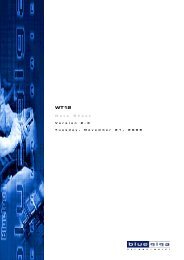
Fig. 1–1: Block diagram of the <strong>UAC</strong> <strong>357xB</strong><br />
Active Stereo Speakers<br />
USB<br />
<strong>UAC</strong> <strong>357xB</strong><br />
Headset<br />
Stereo Equipment<br />
Multichannel Audio<br />
(e.g., Dolby Digital)<br />
Additional DSP<br />
(MAS 3587F)<br />
Digital Audio I/O<br />
(e.g., MP3)<br />
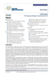
Fig. 1–2: System application diagram<br />
Micronas Aug. 20, 2004; 6251-650-1AI 5
<strong>UAC</strong> <strong>357xB</strong><br />
ADVANCE INFORMATION<br />
2. Hardware Description<br />
VBUS<br />
D− D+<br />
32<br />
36 37<br />
USB<br />
Transceiver<br />
35<br />
VREG<br />
SOF<br />
47<br />
Micro-<br />
Controller<br />
USB<br />
Interface<br />
Volt.<br />
Reg.<br />
GPIO<br />
12<br />
11<br />
17<br />
18<br />
19<br />
20<br />
28<br />
27<br />
26<br />
25<br />
24<br />
23<br />
22<br />
21<br />
STRB<br />
RD<br />
ADR3/GPIO11<br />
/PWM<br />
ADR2/GPIO10<br />
ADR1/GPIO9<br />
ADR0/GPIO8<br />
GPIO0<br />
GPIO1<br />
GPIO2<br />
GPIO3<br />
GPIO4<br />
GPIO5<br />
GPIO6<br />
GPIO7<br />
XTI<br />
XTO<br />
1<br />
2<br />
Oscillator<br />
and<br />
PLL<br />
Audio Control<br />
Interface<br />
Audio<br />
Streaming<br />
Interface<br />
Compressed<br />
Audio<br />
Output<br />
Control<br />
I/O<br />
44<br />
31<br />
45<br />
46<br />
48<br />
TEST<br />
TRDY<br />
RES<br />
SUSPEND<br />
SEN<br />
I 2 C<br />
30<br />
29<br />
SCL<br />
SDA<br />
MICINL<br />
MICINR<br />
ADCL<br />
ADCREF<br />
62<br />
56<br />
60<br />
59<br />
Select<br />
2-Ch.<br />
ADC<br />
Audio Processing Unit (APU)<br />
I 2 S<br />
41<br />
43<br />
42<br />
16<br />
13<br />
14<br />
15<br />
40<br />
USBCLK<br />
USBDAT<br />
USBWSO<br />
DAO<br />
DAI<br />
WSI<br />
CLI<br />
MCLK<br />
ADCR<br />
58<br />
MICBIAS<br />
VDD<br />
VSS<br />
AVDD<br />
AREG0<br />
AREG1<br />
AVSS0<br />
AVSS1<br />
61<br />
39<br />
38<br />
10<br />
9<br />
3<br />
5<br />
4<br />
Mic Bias<br />
Supply<br />
Voltage Reg.<br />
Reference<br />
2-Channel DAC<br />
Analog Filter<br />
Analog Volume<br />
53<br />
52<br />
54<br />
50<br />
49<br />
51<br />
FOPR<br />
FOUTR<br />
FINR<br />
FOPL<br />
FOUTL<br />
FINL<br />
SGND<br />
SREF<br />
SREFO<br />
63<br />
64<br />
55<br />
Headphone Amp.<br />
6 7<br />
8<br />
OUTC<br />
OUTL<br />
OUTR<br />
Fig. 2–1: Detailed block diagram of the <strong>UAC</strong> <strong>357xB</strong><br />
6 Aug. 20, 2004; 6251-650-1AI Micronas
ADVANCE INFORMATION<br />
<strong>UAC</strong> <strong>357xB</strong><br />
2.1. General Information<br />
This description summarizes all hardware platform<br />
capabilities of the <strong>UAC</strong> <strong>357xB</strong>. The function of a certain<br />
application, however, is defined in the microcontroller’s<br />
firmware. This is explained in Section 4. “Firmware”<br />
on page 22 for the standard codec and headset<br />
firmware.<br />
The basic functions (playback, recording, audio control,<br />
HID) of the <strong>UAC</strong> <strong>357xB</strong> can entirely be used by<br />
any USB operating system without additional drivers.<br />
However, the IC offers far more functionality if vendorspecific<br />
controlling or download code is used. With<br />
external I 2 C controlling, the IC can even work as an<br />
audio codec in a non-USB environment. The use of<br />
this <strong>com</strong>plete functionality is not described in the standard<br />
data sheet and can be found in separate application<br />
notes (www.micronas.<strong>com</strong>).<br />
A detailed block diagram of the <strong>UAC</strong> <strong>357xB</strong> is depicted<br />
in Fig. 2–4. The functions of the blocks are explained<br />
in the following sections.<br />
2.2. Universal Serial Bus (USB)<br />
2.2.1. Transceiver<br />
The differential input transceiver is used to handle the<br />
USB data signal according to the full-speed (12 MB/s)<br />
USB driver characteristics (USB SPEC 2.0). This block<br />
is supplied by an internal voltage regulator. The internal<br />
pull-up resistor on the D+ line, indicating that the<br />
<strong>UAC</strong> <strong>357xB</strong> is connected to the USB bus, can be<br />
switched on and off by firmware.<br />
2.2.2. USB Interface<br />
The USB interface does all the low-level USB protocol<br />
handling, such as NRZI coding, bit stuffing and CRC<br />
<strong>com</strong>putation. A receiver/transceiver logic handles the<br />
data traffic between the USB bus and the microcontroller<br />
memory.<br />
2.2.3. Microcontroller<br />
The microcontroller is an 8-bit RISC controller which<br />
handles the Chapter-9 processing and the decoding of<br />
class and vendor-specific USB requests. Detailed<br />
information is available in a separate document. The<br />
basic configuration is:<br />
– 2 KB RAM<br />
– 12 KB ROM<br />
In addition to that, the <strong>UAC</strong> <strong>357xB</strong> has an 8 KB RAM,<br />
which can be used instead of the lower 8 KB ROM for<br />
emulation purposes or as a RAM extension to the<br />
standard 2 KB RAM.<br />
In the emulation mode, the <strong>UAC</strong> <strong>357xB</strong> loads the 8 KB<br />
RAM via I 2 C from an external EEPROM, disables the<br />
lower 8 KB ROM after that, and restarts the microcontroller,<br />
executing the code from RAM.<br />
Another part of the RAM is reserved for download<br />
plug-ins. This is available in both Type 2 and<br />
<strong>UAC</strong> <strong>357xB</strong>, and allows the addition of smaller portions<br />
of code to the basic firmware for extended functions<br />
or workarounds, if necessary. One example is<br />
adding extra functions to the GPIO pins, like control of<br />
external <strong>com</strong>ponents via USB. Downloading of the<br />
plug-in can be done either from the USB host with an<br />
extra driver or from an external I 2 C EEPROM.<br />
Micronas Aug. 20, 2004; 6251-650-1AI 7
<strong>UAC</strong> <strong>357xB</strong><br />
ADVANCE INFORMATION<br />
2.3. GPIO<br />
There are two groups of different types of GPIOs:<br />
– Input and output pins: GPIO[0…11]<br />
– Control pins: RD, STRB<br />
GPIO[11:8]<br />
GPIO[7:0]<br />
(Address is driven by <strong>UAC</strong> 355xB)<br />
Address<br />
(External device drives data lines)<br />
Data<br />
RD<br />
STRB<br />
83 ns 166 ns (typical)<br />
<strong>UAC</strong> <strong>357xB</strong> reads data here<br />
GPIO Address Mode: Read<br />
Fig. 2–2: <strong>UAC</strong> <strong>357xB</strong> parallel interface timing (read)<br />
GPIO[11:8]<br />
GPIO[7:0]<br />
(Address is driven by <strong>UAC</strong> 355xB)<br />
Address<br />
(<strong>UAC</strong> 355xB drives data lines)<br />
Data<br />
RD<br />
STRB<br />
83 ns 166 ns (typical)<br />
valid data<br />
GPIO Address Mode: Write<br />
Fig. 2–3: <strong>UAC</strong> <strong>357xB</strong> parallel interface timing (write)<br />
The port pins can also be set into different electrical<br />
states:<br />
– weak or strong driver strength<br />
– output or tristate<br />
– internal pull-down on or off<br />
There are two GPIO pins with special alternate functions<br />
(see Table 2–1)<br />
– GPIO[10] - Start Timer<br />
– GPIO[11] - PWM Output<br />
A description of these functions can be found in Section<br />
2.4. “General Purpose Timer” on page 10.<br />
8 Aug. 20, 2004; 6251-650-1AI Micronas
ADVANCE INFORMATION<br />
<strong>UAC</strong> <strong>357xB</strong><br />
2.3.1. GPIO Port Configurations<br />
The <strong>UAC</strong> <strong>357xB</strong> can set the GPIO port into different<br />
configurations.<br />
Standard mode<br />
In this mode the GPIO[0…11] pins are used as normal<br />
I/O pins, which can be set or read from the microcontroller.<br />
Address mode<br />
In this mode the GPIO pins can be used in a memory<br />
mapped fashion. There is a 16-Byte range of the<br />
microcontrollers address space which is transparent to<br />
the GPIOs. GPIO[0…7] are mapped to the data bus<br />
and GPIO[8…11] are mapped to the lower four bits of<br />
the address bus.<br />
Table 2–1: GPIO port configurations<br />
Pin name Standard mode Address mode<br />
GPIO[0] Generic I/O Generic parallel I/O<br />
GPIO[1] Generic I/O Generic parallel I/O<br />
GPIO[2] Generic I/O Generic parallel I/O<br />
GPIO[3] Generic I/O Generic parallel I/O<br />
GPIO[4] Generic I/O Generic parallel I/O<br />
GPIO[5] Generic I/O Generic parallel I/O<br />
GPIO[6] Generic I/O Generic parallel I/O<br />
GPIO[7] Generic I/O Generic parallel I/O<br />
GPIO[8] Generic I/O Addr [0]<br />
GPIO[9] Generic I/O Addr [1]<br />
GPIO[10]<br />
GPIO[11]<br />
– Generic I/O<br />
– Start timer<br />
– Generic I/O<br />
– PWM out<br />
Addr [2]<br />
Addr [3]<br />
RD no function Shows I/O direction<br />
Read (high level) input<br />
Write (low level) output - timing diagram<br />
STRB no function Strobe pulse, marks valid data<br />
Micronas Aug. 20, 2004; 6251-650-1AI 9
<strong>UAC</strong> <strong>357xB</strong><br />
ADVANCE INFORMATION<br />
2.4. General Purpose Timer<br />
The <strong>UAC</strong> <strong>357xB</strong> audio codec family incorporates a<br />
timer. It is a 16-bit counter with clock prescaler. The<br />
clock runs at 12 MHz. The prescaler can be set to<br />
divide by 1 to 256.<br />
The current value of the counter can always be read<br />
back.<br />
2.5. Audio Interface<br />
2.5.1. Audio Streaming Interface<br />
The audio streaming interface directly connects the<br />
USB interface to the APU in order to transmit the digital<br />
audio data in both directions for playback and<br />
record. The following data formats are supported:<br />
The timer initiates interrupts on reaching the count<br />
value MaxA.<br />
The <strong>UAC</strong> <strong>357xB</strong> can start the timer with a “high” level<br />
on GPIO[10].<br />
Table 2–2: Audio Formats<br />
Playback<br />
16-bit mono<br />
Record<br />
8-bit mono<br />
The timer can be switched to PWM generation to configure<br />
GPIO[11] as PWM output.<br />
The structure of the timer is shown in Fig. 2–4. The<br />
PWM output and timer frequencies can be calculated<br />
as shown in Figure 2–4.<br />
16-bit stereo<br />
16-bit mono<br />
24-bit stereo<br />
16-bit stereo<br />
2.5.2. Audio Control Interface<br />
GPIO[10]<br />
EXT_ENB<br />
Timer Interrupt<br />
PWM GPIO[11]<br />
Control<br />
The Audio Control Interface links the microcontroller to<br />
the APU and is used to initialize the APU and to transmit<br />
audio-related USB control data, such as volume<br />
setting, tone control etc.<br />
The Audio Control Interface supports full access to all<br />
APU registers via the microcontroller.<br />
2.5.3. Serial Data Output<br />
12 MHz<br />
Prescaler<br />
Tclk<br />
Counter<br />
Used Pins: USBCLK, USBDAT<br />
Max A<br />
Max B<br />
This interface provides a data path for transferring<br />
<strong>com</strong>pressed audio to peripheral ICs, such as Micronas’<br />
Dolby Digital decoder MAS 3530H or to an MP3<br />
decoder, e.g., the MAS 3507D or MAS 3509F. This<br />
works independently from the normal USB playback.<br />
The audio format on the USB-OUT pins is burst I 2 S.<br />
Fig. 2–4: Timer structure<br />
Note: If this interface is used, the “Asynchronous I 2 S<br />
input with optional I 2 S output” is not available<br />
and vice versa.<br />
Timer frequency:<br />
Tclk = 12 MHz / Prescale<br />
PWM frequency:<br />
PWM = Tclk / (MaxA + MaxB)<br />
MaxA MaxB MaxA MaxB<br />
Fig. 2–5: PWM timing<br />
This interface operates in different modes:<br />
2.5.4. Direct Streaming<br />
In this mode, there is no preprocessing of the timing,<br />
i.e., the data on USBDAT are in phase with the 12 MHz<br />
data on the USB bus, which are sent to a specific endpoint.<br />
This can be bulk or isochronous data. The data<br />
appear as they are sent on the USB bus.<br />
10 Aug. 20, 2004; 6251-650-1AI Micronas
ADVANCE INFORMATION<br />
<strong>UAC</strong> <strong>357xB</strong><br />
2.5.5. Microcontroller Streaming<br />
In this mode, the microcontroller copies the data from<br />
the RAM to a shift register, which is connected to the<br />
USBDAT pin. The shift clock can be programmed<br />
between 6 MHz and 750 kHz and appears on USB-<br />
CLK pin.<br />
2.6.2. Asynchronous I 2 S Input<br />
Used Pins: DAI, WSI, CLI<br />
In this mode the <strong>UAC</strong> <strong>357xB</strong> is slave, i.e., asynchronous<br />
input is possible at a sampling rate range from<br />
6.4 kHz to 48 kHz. The external I 2 S source provides<br />
DAI, WSI, and CLI<br />
2.6. The <strong>UAC</strong> <strong>357xB</strong> Serial Audio Interfaces<br />
Used Pins: DAO, DAI, WSI, CLI, USBDAT, USBCLK<br />
The <strong>UAC</strong> <strong>357xB</strong> offers two digital serial interfaces<br />
(I2S). They are directly connected to the APU.<br />
The I 2 S interfaces operate in 16-bit or 32-bit mode.<br />
The master clock (MCLK) is programmable to<br />
18.432 MHz, 24.576 MHz or 36.864 MHz. Delayed<br />
word strobe or standard I 2 S format can be selected via<br />
the programmable delay bit. Word strobe polarity is<br />
programmable, too. Detailed timing diagrams can be<br />
found in Section 5.6.5. “I2S Interface Timing Characteristics”<br />
on page 49.<br />
<strong>UAC</strong> <strong>357xB</strong><br />
DAI<br />
CLI<br />
WSI<br />
asynchronous<br />
input<br />
2.6.1. Synchronous I 2 S Input/Output<br />
Used Pins: DAO, DAI, WSI, CLI<br />
In this mode, the <strong>UAC</strong> <strong>357xB</strong> is master on the I 2 S, i.e,<br />
it generates WSI and CLI for a fixed 48 kHz sampling<br />
rate. External I 2 S sources must deliver data synchronous<br />
to the output.<br />
Fig. 2–7: Asynchronous I 2 S input<br />
2.6.3. Asynchronous I 2 S Input With Optional I 2 S<br />
Output<br />
Used Pins:<br />
Output:USBDAT, USBCLK, USBWSO<br />
Input: WSI, CLI, DAI<br />
<strong>UAC</strong> <strong>357xB</strong><br />
DAI<br />
CLI<br />
WSI<br />
DAO<br />
synchronous<br />
input/output<br />
In this mode the I 2 S burst interface pins USBDAT,<br />
USBCLK and USBWSO can be used for synchronous<br />
I 2 S output (if the burst interface is not used), as<br />
described in Figure 2.6.1. The I 2 S input pins WSI, CLI,<br />
DAI, however, operate asynchronously as described in<br />
Section 2.6.2.<br />
USBDAT<br />
MCLK (optional)<br />
Fig. 2–6: Synchronous I 2 S Input/Output<br />
<strong>UAC</strong> <strong>357xB</strong><br />
USBCLK<br />
USBWSO<br />
DAI<br />
CLI<br />
WSI<br />
synchronous<br />
output<br />
asynchronous<br />
input<br />
Fig. 2–8: Asynchronous I 2 S input with optional<br />
I 2 S output<br />
Micronas Aug. 20, 2004; 6251-650-1AI 11
<strong>UAC</strong> <strong>357xB</strong><br />
ADVANCE INFORMATION<br />
2.7. Power Supply<br />
The <strong>UAC</strong> <strong>357xB</strong> has on-chip voltage regulators providing<br />
the optimal supply voltages for the analog and digital<br />
sections, thus allowing to power the IC by the USB<br />
Bus supply lines, as well as from external supply. They<br />
also serve to reduce cross-talk and EMI.<br />
For stable operation, all regulators need external<br />
capacitors.<br />
2.8. I 2 C Bus Interface<br />
Pins: SDA, SCL<br />
The <strong>UAC</strong> <strong>357xB</strong> is equipped with an I 2 C bus master/<br />
slave interface. Bus format and timing follow the original<br />
specification for I 2 C (The I 2 C Specification V2.1).<br />
It operates with 5 V signalling at 100 kHz or 400 kHz.<br />
Both master and slave mode require support from the<br />
microcontroller firmware.<br />
The regulators are<br />
1. VREG:<br />
3.4 V regulator for USB-signalling (saving external<br />
regulator)<br />
2. AREG0:<br />
3.5 V regulator for analog back-end<br />
3. AREG1:<br />
3.5 V regulator for analog circuitry apart from backend.<br />
Reference voltage for analog signals:<br />
SREF:<br />
1.7 V (optional 2.3 V) reference voltage for analog circuitry.<br />
In applications, for example home stereo equipment<br />
with noisy ground levels, however, it is better that<br />
the reference follows the AC-<strong>com</strong>ponent of the external<br />
ground system. This results in a <strong>com</strong>pensation of<br />
the noise. This AC-<strong>com</strong>ponent can be coupled into pin<br />
SREF0.<br />
Note: It is re<strong>com</strong>mended for AVSS0/1, SGND and<br />
VSS to be connected.<br />
2.8.1. I 2 C Master<br />
This mode allows control of external I 2 C devices, such<br />
as EEPROMs, LCD-Displays etc. This interface is<br />
used to download configuration data and firmware<br />
from an EEPROM after power-up. The bus protocol<br />
(subaddressing and packet length) is defined by firmware<br />
and therefore programmable.<br />
Note: Micronas standard firmware (Section 4. “Firmware”<br />
on page 22) provides support for USB to<br />
I 2 C bridging, allowing control of I 2 C devices via<br />
USB.<br />
2.8.2. I 2 C Slave<br />
In I 2 C slave mode, the interface provides an interrupt<br />
to the microcontroller after detecting the assigned I 2 C<br />
address (0x48). The corresponding interrupt service<br />
routine handles this request and interprets in<strong>com</strong>ing<br />
data according to the application.<br />
One example of handling could provide full access to<br />
all memory locations.<br />
Five-Volt Mode<br />
If a higher output level is required, the IC can operate<br />
in 5 V mode. In this case, the IC is powered from an<br />
external 5 V supply: AVDD has to be connected to<br />
AREG0 and AREG1 and SREF must be switched to<br />
5 V mode.<br />
12 Aug. 20, 2004; 6251-650-1AI Micronas
ADVANCE INFORMATION<br />
<strong>UAC</strong> <strong>357xB</strong><br />
2.9. Dual Microphone and Stereo Line Inputs<br />
Pins: ADCR, ADCL, MICINL, MICINR, MICBIAS,<br />
ADCREF<br />
The <strong>UAC</strong> <strong>357xB</strong> provides a 2-channel ADC. The A/D<br />
converters achieve a signal-to-noise ratio better than<br />
90 dB (typ.) and a bandwidth of 20 kHz (at f s =48 kHz).<br />
The ADCs can be used either for stereo line or dual<br />
microphone input. Mixed mode mic/line is possible<br />
also.<br />
2.9.1. Line Input<br />
Line signals can be coupled in a pseudo-differential<br />
way. This means an external ground reference can be<br />
coupled into pin ADCREF (AC-coupled).<br />
The input gain for the line input is programmable in the<br />
range of −3 dB to 19.5 dB. Table 2–3 shows the line<br />
input voltage versus gain setting and the input impedance<br />
(depends on gain setting) for full range ADC<br />
input (clipping level).<br />
Note: Coupling caps for ADCL, ADCR, ADCREF must<br />
be identical for optimum performance.<br />
Table 2–3: Line input levels<br />
Line Input<br />
Voltage<br />
[mVpp]<br />
3V Mode<br />
Line Input<br />
Voltage<br />
[mVpp]<br />
5V Mode<br />
Gain<br />
Setting [dB]<br />
3388 4517 −3 85<br />
2851 3801 −1.5 79<br />
2399 3198 0 73<br />
2018 2691 1.5 67<br />
1698 2264 3 61<br />
1429 1905 4.5 55<br />
1202 1603 6 49<br />
1011 1349 7.5 44<br />
851 1135 9 39<br />
716 955 10.5 34<br />
602 803 12 30<br />
507 676 13.5 26<br />
427 569 15 23<br />
Input<br />
Impedance<br />
[kΩ]<br />
359 478 16.5 19<br />
302 403 17 17<br />
254 339 19.5 14<br />
Micronas Aug. 20, 2004; 6251-650-1AI 13
<strong>UAC</strong> <strong>357xB</strong><br />
ADVANCE INFORMATION<br />
2.9.2. Microphone Input<br />
The <strong>UAC</strong> <strong>357xB</strong> allows direct connection to electret<br />
microphones and provides the microphone bias voltage<br />
of 3.1 V (2 x1.0 mA max.) on a separate pin, too.<br />
There is a fixed +21.5 dB gain followed by a programmable<br />
gain of 0 dB to +22.5 dB. Table 2–4 shows the<br />
microphone voltage versus gain setting and the input<br />
impedance (depends on gain setting) for full range<br />
ADC input (clipping level).<br />
Mic<br />
L<br />
Line<br />
Mic<br />
R<br />
Line<br />
Preamp<br />
Preamp<br />
Mic-Bias<br />
A<br />
D<br />
A<br />
D<br />
Q-Peak<br />
Mono<br />
Note: For optimum MICBIAS connection, see Fig. 6–2<br />
on page 52.<br />
Fig. 2–9: Analog input configuration<br />
Table 2–4: Microphone input levels<br />
Microphone<br />
Voltage<br />
[mV PP ]<br />
3V Mode<br />
Microphone<br />
Voltage<br />
[mV PP ]<br />
5V Mode<br />
Gain<br />
Setting [dB]<br />
Input<br />
Impedance<br />
[kΩ]<br />
283 377 0 137<br />
238 317 1.5 117<br />
200 267 3 100<br />
168 225 4.5 85<br />
142 189 6 72<br />
119 159 7.5 62<br />
100 134 9 52<br />
84 113 10.5 44<br />
71 95 12 37<br />
60 80 13.5 32<br />
50 67 15 27<br />
42 56 16.5 23<br />
36 47 17 19<br />
30 40 19.5 16<br />
25 34 21 14<br />
21 28 22.5 11<br />
After A/D conversion there is a digital quasi-peak<br />
meter providing level information in APU register.<br />
There is the option to switch the L-signal to both channels<br />
for mono applications. The quasi-peak meterreadout<br />
allows to control level meters or an AGC for<br />
the analog input.<br />
14 Aug. 20, 2004; 6251-650-1AI Micronas
ADVANCE INFORMATION<br />
<strong>UAC</strong> <strong>357xB</strong><br />
2.10. Analog Output<br />
Pins: OUTL, OUTR, FOPL, FOPR, FOUTL, FOUTR,<br />
FINL, FINR, OUTC, SREF0<br />
The analog output system <strong>com</strong>prises the stereo audio<br />
DAC, analog filters, op-amps for external out-of-bandnoise<br />
filters, analog volume, mute, and the output<br />
amplifiers.<br />
2.10.4.1. Stereo Headphone Mode<br />
Stereo headphones can directly be connected to<br />
OUTL and OUTR pins without coupling capacitors,<br />
because pin OUTC provides the signal reference. This<br />
mode results in degradation of SNR (−3 dB). If this not<br />
acceptable, the normal connection mode is still possible.<br />
2.10.1. Digital-to-Analog Converters<br />
The <strong>UAC</strong> <strong>357xB</strong> uses two multibit sigma-delta DACs<br />
with high linearity and SNR better than 95 dBA.<br />
2.10.2. Analog Filter<br />
Pins: FOPL, FOPR, FOUTL, FOUTR, FINL, FINR<br />
This block contains the op-amps for the optional analog<br />
external out-of-band-noise filters. It is re<strong>com</strong>mended<br />
to use a second-order filter for the main channels<br />
(OUTL, OUTR) (see Section 6. “<strong>UAC</strong> <strong>357xB</strong><br />
Applications” on page 51). It is possible to omit these<br />
filters and to save the external <strong>com</strong>ponents. In this<br />
case, the filter op-amp has to be switched off and the<br />
pins FOUTL/R, FINL/R and FOPL/R must be connected.<br />
The output signal will contain more out-ofband<br />
noise, which is not audible, however.<br />
2.10.3. Analog Volume<br />
The analog volume covers a range from +6 dB to<br />
−18 dB with 1.5 dB step size. But this is the analog<br />
<strong>com</strong>ponent of the overall volume system which covers<br />
a range from +12 dB to −114dB with 1dB step size<br />
and additional mute position. It is split into analog and<br />
digital volume. This splitting ensures that the DAC performance<br />
parameters do not degrade at reduced volume<br />
settings. The splitting is embedded in the audio<br />
processing and cannot be modified.<br />
OUTL<br />
OUTC<br />
OUTR<br />
OUTC<br />
Fig. 2–10: Stereo headphone capless connection.<br />
OUTL<br />
AVSS<br />
OUTR<br />
AVSS<br />
Fig. 2–11: Stereo headphone normal connection<br />
Note: Positive volumes will degrade the THD at high<br />
input levels.<br />
2.10.4. Line-out/Headphone Amplifier<br />
Pins: OUTL, OUTR, OUTC, SREFO<br />
Micronas Aug. 20, 2004; 6251-650-1AI 15
<strong>UAC</strong> <strong>357xB</strong><br />
ADVANCE INFORMATION<br />
2.10.4.2. Line Out Mode<br />
In line out mode 1) it is possible to reduce external<br />
ground noise by AC-coupling of the external ground to<br />
the pin SREFO. This method is re<strong>com</strong>mended in home<br />
stereo equipment with USB connection to a PC. If the<br />
home stereo system uses an antenna, the use of an<br />
additional antenna insulator is re<strong>com</strong>mended to avoid<br />
hum.<br />
Alternatively, external ground can be connected to<br />
AVSS while SREFO is left open. However, care must<br />
be taken to avoid ground loop noise.<br />
OUTL<br />
2.10.4.3. Mono Speaker Mode<br />
In mono speaker mode, the DC coupling capacitors<br />
are not required. In this mode, the output pins OUTL/R<br />
operate in bridge mode with <strong>com</strong>plementary signals.<br />
Therefore, the maximum output power increases,<br />
allowing small speakers to be driven directly.<br />
OUTR<br />
OUTL<br />
Fig. 2–13: Loudspeaker connection for mono mode 2)<br />
2.11. Special I/O<br />
OUTR<br />
SREFO<br />
Pins: SOF, SEN, SUSPEND, RESET<br />
The following sections describe some pins with special<br />
functions.<br />
Fig. 2–12: Lineout mode with ground noise<br />
<strong>com</strong>pensation<br />
2.11.1. SOF (Start of Frame)<br />
The SOF pin provides a 1 ms periodic signal which is<br />
derived from the USB frame rate. It can be used for<br />
test purpose or as an USB-synchronous reference for<br />
vendor-specific external circuitry.<br />
1) this is not a standard line out, because all audio processing<br />
is active on the analog output.<br />
2) load capacitance must not exceed 400pF at OUTL,<br />
OUTR and OUTC. Otherwise series resistors are<br />
required.<br />
16 Aug. 20, 2004; 6251-650-1AI Micronas
ADVANCE INFORMATION<br />
<strong>UAC</strong> <strong>357xB</strong><br />
2.11.2. SEN (Suspend Enable)<br />
Pin: SEN<br />
This is a digital input that prevents the device from<br />
entering the low-power mode (Suspend). The<br />
<strong>UAC</strong> <strong>357xB</strong> enters a low-power mode if:<br />
– there is J-state on D+, D− lines (USB-Suspend) and<br />
V bus high<br />
– V bus is low (USB disconnected)<br />
AVDD<br />
VDD<br />
RES<br />
90%<br />
20 ms<br />
Note: Both cases must be supported by the firmware<br />
In case of USB-Suspend, the SEN pin is also used as<br />
an input for the remote wake-up function.<br />
Table 2–5: SEN pin<br />
Fig. 2–14: Timing diagram of the reset procedure<br />
2.12. Clock System<br />
Pins: XTI, XTO<br />
SEN<br />
high<br />
low<br />
suspend enabled<br />
suspend disabled/remote wake-up<br />
The <strong>UAC</strong> <strong>357xB</strong> requires a 12 MHz clock source,<br />
which is realized as an on-chip oscillator with external<br />
crystal. Also an external oscillator can be used. In this<br />
case, the clock has to be connected to XTI (see also<br />
Section 6. “<strong>UAC</strong> <strong>357xB</strong> Applications” on page 51). The<br />
12 MHz is the input clock for a PLL circuit which generates<br />
all clocks needed within the IC.<br />
2.11.3. Suspend<br />
Pin: SUSPEND<br />
The SUSPEND pin is a digital output pin which indicates<br />
the low-power mode. It can be used to power<br />
down external circuitry, such as power amplifiers in a<br />
USB speaker.<br />
The clock for the APU is programmable either to<br />
48 MHz or 72 MHz. In case of 48 MHz, the<br />
<strong>UAC</strong> <strong>357xB</strong> consumes less power, but on the other<br />
hand a reduced feature-set for the audio processing<br />
has to be taken into account (see Fig. 3–1 on<br />
page 18).<br />
Table 2–6: SUSPEND pin<br />
SUSPEND<br />
high<br />
low<br />
normal power<br />
low power<br />
2.11.4. Reset<br />
Pin: RES<br />
The RES pin resets the <strong>UAC</strong> <strong>357xB</strong>. The timing of the<br />
RESET after power up is not critical. An internal circuitry<br />
handles the correct timing and ensures that all<br />
clocks are active before the reset is released internally.<br />
In low-power mode, the RES pin must not be low to<br />
avoid restart of the clock system and therefore entering<br />
normal power mode.<br />
Micronas Aug. 20, 2004; 6251-650-1AI 17
18 Aug. 20, 2004; 6251-650-1AI Micronas<br />
3. Audio Processing<br />
Mic<br />
Line<br />
Mic<br />
L Preamp A<br />
R<br />
A<br />
USB<br />
I 2 S<br />
(downstream)<br />
Mic-Bias<br />
I 2 S Synchronous Mode only<br />
in reduced feature set<br />
Q-Peak<br />
D<br />
D<br />
Mono<br />
Deemphasis<br />
off/50 µs/75 µs<br />
ADC<br />
Fig. 3–1: Signal flow in the audio processing unit (APU)<br />
mix<br />
USB<br />
mix<br />
I 2 S<br />
mix<br />
DSP-Loop<br />
Complementary<br />
High<br />
Pass<br />
Bass/<br />
Treble/<br />
AGC<br />
Loudness<br />
Q-Peak<br />
<strong>com</strong>plete mix<br />
ADC+USBmix<br />
ADC input<br />
USB L/R<br />
I 2 S input<br />
<strong>com</strong>plete mix<br />
ADC+USBmix<br />
ADC input<br />
USB L/R<br />
I 2 S input<br />
5<br />
4<br />
0<br />
1<br />
2<br />
3<br />
5<br />
4<br />
0<br />
1<br />
2<br />
3<br />
Select<br />
Select<br />
EQ<br />
dashed blocks not available in reduced feature set<br />
Scale<br />
Scale<br />
Mono/<br />
Stereo<br />
+<br />
Right<br />
Invert<br />
USB (upstream)<br />
I 2 S out<br />
Balance<br />
Vol.<br />
D<br />
D<br />
A<br />
A<br />
L<br />
R<br />
<strong>UAC</strong> <strong>357xB</strong> ADVANCE INFORMATION
ADVANCE INFORMATION<br />
<strong>UAC</strong> <strong>357xB</strong><br />
The audio processing is realized by APU firmware.<br />
The audio building blocks can be split into USB-independent<br />
features such as parametric equalizer, I 2 S<br />
I/O, and blocks which belong to USB feature units,<br />
mixer units, and selection units defined in the USB<br />
Device Class Definition for Audio Devices.<br />
Output Level<br />
dBr<br />
−9<br />
AGC off<br />
AGC on<br />
The USB feature unit provides basic manipulation of<br />
the in<strong>com</strong>ing logical channels and can be controlled by<br />
the standard windows mixer tool. The parameters for<br />
the USB-independent features are predefined in the<br />
internal ROM, in an external EEPROM or a special<br />
host application which drives the IC.<br />
The <strong>UAC</strong> <strong>357xB</strong> supports two logical channels (i.e. left<br />
and right). Multichannel or surround systems, however,<br />
can also be realized using more than one<br />
<strong>UAC</strong> <strong>357xB</strong>, because phase or delay distortion is eliminated<br />
in the device by locking the audio processing to<br />
the USB frame rate. An overview of the architecture is<br />
given in Fig. 3–1 on page 18.<br />
−15<br />
−21<br />
−30 −24 −18 −12 −6 0 +6<br />
dBr<br />
Input Level<br />
Fig. 3–2: Simplified AGC characteristics<br />
Table 3–1: AGC parameters<br />
Parameter Settings Default<br />
If the APU works with a 48 MHz clock it is necessary to<br />
select the reduced feature mode. The blocks, which<br />
are not available in reduced feature mode are shown<br />
with dashed lines in Fig. 3–1 on page 18.<br />
Decay time<br />
8 seconds<br />
4 seconds<br />
2 seconds<br />
20 ms<br />
4 seconds<br />
3.1. DSP Loop<br />
The DSP-Loop block symbolizes the option to route<br />
the audio signal to an external DSP and back into the<br />
<strong>UAC</strong> <strong>357xB</strong> via I²S I/O. This allows to add more audio<br />
processing algorithms.<br />
3.2. Automatic Gain Control<br />
The Automatic Gain Control (AGC) is one of the building<br />
blocks of the feature unit (USB Device Class Definition<br />
for Audio Devices 1.0, page 39).<br />
Different sound sources fairly often do not have the<br />
same volume level. The Automatic Gain Control solves<br />
this problem by equalizing the volume levels within a<br />
defined range. Below a threshold level the signals are<br />
not affected. The level-adjustment is performed with<br />
time constants in order to avoid short-time adjustments<br />
due to signal peaks.<br />
3.3. Quasi-Peak<br />
Two quasi-peak detectors are provided:<br />
1. after the ADCs. This allows the programming of an<br />
AGC in the microcontroller 1) or a VU-meter on the<br />
host side.<br />
2. in the DAC channel. This can be used, e.g., for a<br />
VU-meter on the host side.<br />
The feature is based on using fast attack and slow<br />
decay time constants.<br />
3.4. Bass Control<br />
The bass control provides gain or attenuation to frequency<br />
<strong>com</strong>ponents below a corner frequency of<br />
120 Hz. The bass control works identically on both<br />
channels in a range of −12 dB to +12 dB.<br />
3.5. Treble Control<br />
The treble control provides gain or attenuation to frequency<br />
<strong>com</strong>ponents above a corner frequency of<br />
6 kHz. The treble control works identically on both<br />
channels in a range of −12 dB to +12 dB.<br />
1) not supported by standard microcontroller firmware<br />
Micronas Aug. 20, 2004; 6251-650-1AI 19
<strong>UAC</strong> <strong>357xB</strong><br />
ADVANCE INFORMATION<br />
3.6. Parametric Equalizer<br />
3.8. Micronas Dynamic Bass (MB)<br />
The parametric equalizer is an audio feature which is<br />
not accessed via standard USB controls. It allows the<br />
<strong>com</strong>pensation of the frequency response of a speaker.<br />
Alternatively, frequency responses can be set to suit<br />
individual tastes. The equalizer consists of 5 individually<br />
adjustable bands. The control parameters and the<br />
parameter range for each band is shown in Table 3–2.<br />
Table 3–2: Equalizer parameters<br />
Parameter Min Max<br />
Center Frequency 50 Hz 15 kHz<br />
Gain/Attenuation −6 dB +6dB<br />
Filter Quality (Q) 0.5 3 Table 3–3: MB parameters<br />
The Micronas Dynamic Bass algorithm (MB) implements<br />
a sophisticated bass boost system, which<br />
extends the frequency range of loudspeakers or headphones.<br />
For applications without a subwoofer, the enhanced<br />
bass signal can be added back onto the left/right channels.<br />
Micronas Dynamic Bass <strong>com</strong>bines two effects:<br />
dynamic amplification and adding harmonics.<br />
Several parameters allow tuning the characteristics of<br />
MB according to the loudspeaker, the cabinet, and personal<br />
preferences. For more detailed information on<br />
how to set up MB, Micronas will provide an appropriate<br />
Application Note.<br />
The adjustment of the equalizer is supported by an<br />
application program that allows to set up frequency<br />
responses and to download the corresponding filter<br />
coefficients into the <strong>UAC</strong> <strong>357xB</strong>. When the frequency<br />
response matches the requirements, it can be programmed<br />
into the external EEPROM or can be set by<br />
a vendor specific device driver. The <strong>UAC</strong> <strong>357xB</strong> is<br />
shipped with a flat frequency response.<br />
3.7. Volume, Mute, and Balance Control<br />
The volume control is partly realized in the analog<br />
back-end. This preserves high audio quality (SNR) at<br />
low volume settings because signal and noise are<br />
attenuated in the same way. This is not the case for<br />
devices with pure digital volume control. The<br />
<strong>UAC</strong> <strong>357xB</strong> uses digital volume control only for the<br />
fine tuning. The volume setting is smoothed by an<br />
internal ramping algorithm in order to avoid audible<br />
clicks during volume change. The splitting between<br />
analog and digital volume is handled by the<br />
<strong>UAC</strong> <strong>357xB</strong> automatically.<br />
Parameter Range Default if<br />
disabled<br />
Effect<br />
Strength<br />
Harmonic<br />
Content<br />
Center<br />
Frequency<br />
Amplitude<br />
Limit<br />
Default if<br />
enabled<br />
off…max off medium<br />
0…100% 0% 50%<br />
20…300 Hz 90 Hz 90 Hz<br />
−32…0<br />
dBFS<br />
0dBFS<br />
(=no limit)<br />
0dBFS<br />
(=no limit)<br />
The balance is implemented digitally by attenuating<br />
one channel.<br />
The mute control is part of the volume system in the<br />
<strong>UAC</strong> <strong>357xB</strong>. It functions simultaneously on both channels<br />
and can be switched on and off under USB control.<br />
Similar to the volume control, clicks are avoided<br />
by a ramping algorithm.<br />
20 Aug. 20, 2004; 6251-650-1AI Micronas
ADVANCE INFORMATION<br />
<strong>UAC</strong> <strong>357xB</strong><br />
3.8.1. Dynamic Amplification<br />
Since the human impression of loudness depends on<br />
the frequency, a dynamic <strong>com</strong>pression of the low frequencies<br />
adapts the sound to the human perception.<br />
In order to prevent clipping and to adapt the system to<br />
the signal amplitude which is really present at the output<br />
of the device, the MB contains a definable limit.<br />
The output signal amplitude is monitored and if it<br />
<strong>com</strong>es close to the limit, the gain is reduced automatically.<br />
Clipping effects are avoided.<br />
Amplitude<br />
(db)<br />
MDB_LIMIT<br />
Signal Level<br />
MDB_CF<br />
SUBW_FREQ<br />
Frequency<br />
Fig. 3–3: Dynamic amplification<br />
3.8.2. Adding Harmonics<br />
MB exploits the psychoacoustic phenomenon of the<br />
‘missing fundamental’. Adding harmonics of the frequency<br />
<strong>com</strong>ponents below the cutoff frequency gives<br />
the impression of actually hearing the low frequency<br />
fundamental. In other words: Although the loudspeaker<br />
system is not capable of generating such low<br />
frequencies, the listener has the impression that it<br />
reproduces them.<br />
Amplitude (db)<br />
MDB_CF<br />
Frequency<br />
Fig. 3–4: Adding harmonics<br />
Micronas Aug. 20, 2004; 6251-650-1AI 21
22 Aug. 20, 2004; 6251-650-1AI Micronas<br />
4. Firmware<br />
Mic<br />
Line<br />
USB<br />
I 2 S<br />
L<br />
R<br />
Mic<br />
Preamp<br />
Preamp<br />
(downstream)<br />
Mic-Bias<br />
A<br />
A<br />
Q-Peak<br />
D<br />
D<br />
switch to Line-L only for Codec Firmware<br />
Mono<br />
ADC-mix only for headset firmware<br />
Deemphasis<br />
off/50 µs/75 µs<br />
ADC<br />
mix<br />
USB<br />
mix<br />
I 2 S<br />
mix<br />
Fig. 4–1: Signal flow in the audio processing unit controlled by the codec/headset firmware using standard OS driver<br />
AGC<br />
Complementary<br />
High<br />
Pass<br />
Bass/<br />
Treble/<br />
Loudness<br />
Q-Peak<br />
<strong>com</strong>plete mix<br />
ADC+USBmix<br />
ADC input<br />
USB L/R<br />
I 2 S input<br />
<strong>com</strong>plete mix<br />
ADC+USBmix<br />
ADC input<br />
USB L/R<br />
I 2 S input<br />
5<br />
4<br />
0<br />
1<br />
2<br />
3<br />
5<br />
4<br />
0<br />
1<br />
2<br />
3<br />
Select<br />
Select<br />
EQ<br />
Scale<br />
Scale<br />
Mono/<br />
Stereo<br />
+<br />
Right<br />
Invert<br />
USB (upstream)<br />
I 2 S out<br />
Balance<br />
Vol.<br />
D<br />
D<br />
A<br />
A<br />
L<br />
R<br />
<strong>UAC</strong> <strong>357xB</strong> ADVANCE INFORMATION
ADVANCE INFORMATION<br />
<strong>UAC</strong> <strong>357xB</strong><br />
The previous chapters describe the <strong>UAC</strong> <strong>357xB</strong> from<br />
the hardware point of view. The <strong>com</strong>plete functionality,<br />
however, is defined by the microcontroller firmware.<br />
This firmware tailors the device to a specific application.<br />
Micronas offers two standard firmware versions<br />
embedded in the ROM.<br />
– Type 4: Standard Codec<br />
– Type 2: Standard Headset<br />
Note: It is possible to customize many parameters<br />
(IDs, strings, equalizer setting etc.) by means of<br />
an external EEPROM.<br />
Table 4–1: Programmable Device Descriptor Items<br />
Item Default Type 4 Default<br />
Type 2<br />
idVendor 0x074D 0x074D<br />
idProduct 0x3574 0x3574<br />
bcdDevice 0x000x 1) 0x000x 1)<br />
iManufacturer 0x01 0x01<br />
iProduct 0x02 0x02<br />
iSerialNumber 0x00 0x00<br />
1) Changes with firmware revisions<br />
Both firmware versions are very similar. Differences<br />
are mentioned in the following chapters.<br />
4.1. Features<br />
The main features of the standard firmware versions<br />
are:<br />
– USB playback and record with independent sample<br />
rates<br />
– Sample rates from 6.4 kHz to 48 kHz<br />
– Microphone or Line input<br />
(only mic for Type 2)<br />
– Audio baseband processing incl. dynamic bass<br />
management<br />
– Basic audio control by GPIO-HID<br />
– Suspend mode and remote wake-up support<br />
– I 2 C master/slave support<br />
– Bootloader permitting download of configuration<br />
data, plug-ins or <strong>com</strong>plete firmware (only for<br />
<strong>UAC</strong> <strong>357xB</strong>) after power-on<br />
– Plug-in support (downloadable firmware extensions<br />
from external EEPROM or WIN driver).<br />
Most of the functions are defined in the device and<br />
configuration descriptor. The following chapters provide<br />
all noteworthy information, which is buried in this<br />
descriptors. It is assumed that the reader is familiar<br />
with the basic USB notation (USB Spec 2.01/<br />
www.usb.org).<br />
4.2. Device Descriptor<br />
The device descriptor contains the downloadable IDs<br />
and the index for several strings.<br />
Associated to the string index there are three programmable<br />
strings. The ROM firmware defines only two:<br />
Table 4–2: Strings<br />
String Default Type 4 Default Type 2<br />
Manufacturer<br />
String<br />
Micronas<br />
4.3. Configuration Descriptor<br />
Micronas<br />
Product String Type 4 Type 2<br />
The configuration descriptor contains information on<br />
the bus/self-powered and remote wake-up capabilities.<br />
The <strong>UAC</strong> <strong>357xB</strong> allows all <strong>com</strong>binations of these features.<br />
There is also a string index, allowing to associate<br />
a string to this configuration. The default string is a<br />
date code (time of code assembly). These items are<br />
programmable:<br />
Table 4–3: Programmable Configuration Descriptor<br />
Items<br />
Item Default - Type 4 Default - Type 2<br />
iConfig 0x01 0x01<br />
bmAttributes<br />
0xe0<br />
(self-powered,<br />
remote wake-up)<br />
0xa0<br />
(bus-powered,<br />
remote wake-up)<br />
MaxPower 0x00 (0 mA) 0x32 (100 mA)<br />
The configuration descriptor also provides all information<br />
concerning the audio flow in the Class Specific<br />
Audio Control Interface. Fig. 3–1 on page 18 shows<br />
the graphical representation for the codec firmware.<br />
Micronas Aug. 20, 2004; 6251-650-1AI 23
<strong>UAC</strong> <strong>357xB</strong><br />
ADVANCE INFORMATION<br />
USB<br />
Mic<br />
Associated<br />
Input<br />
Terminals<br />
IT<br />
ID11<br />
Mic<br />
EP1<br />
IT<br />
ID12<br />
IT<br />
ID10<br />
FU<br />
SU<br />
Volume, muteID6<br />
ID8<br />
analog gain<br />
“dummy selector units”<br />
FU<br />
SU<br />
Volume ID2<br />
ID7<br />
analog<br />
MU<br />
ID9<br />
Sidetone Mixer<br />
Volume,Mute,<br />
Bass,Treble<br />
BassBoost<br />
AGC<br />
FU<br />
ID1<br />
analog+digital<br />
Playback<br />
OT<br />
ID14<br />
EP4<br />
OT<br />
ID13<br />
Record<br />
D/A<br />
USB-Up<br />
Fig. 4–2: Standard headset audio signal flow<br />
USB<br />
EP1<br />
IT<br />
ID12<br />
Volume,Mute,<br />
Bass,Treble<br />
BassBoost<br />
AGC<br />
FU<br />
ID1<br />
Playback<br />
OT<br />
ID14<br />
D/A<br />
Mic<br />
Line<br />
IT<br />
ID11<br />
IT<br />
ID10<br />
FU<br />
Volume<br />
analog gain<br />
FU<br />
Volume<br />
analog gain<br />
ID2<br />
ID3<br />
SU<br />
ID8<br />
FU<br />
Volume Mute ID5<br />
EP4<br />
OT<br />
ID13<br />
Record<br />
USB-Up<br />
Fig. 4–3: Standard codec audio signal flow<br />
These are the audio structures and how they appear to<br />
the USB host. Without any additional drivers the<br />
Microsoft Windows ® operating system provides sliders<br />
in the mixing tool to control volume setting, selectors<br />
etc. Using a vendor specific application, however, it is<br />
possible to extend this to the full signal routing capabilities<br />
(see Section 3.1. on page 19).<br />
Static modifications (without sliders), like<br />
– adding a sidetone path (analog-in to analog-out) to<br />
the codec firmware<br />
– adding I 2 S I/O<br />
The mapping of this audio structure to the overall<br />
audio processing in the APU is shown in Fig. 4–1 on<br />
page 22. The dashed lines show signal paths which<br />
cannot be activated by standard Windows drivers and<br />
need support of vendor-specific drivers and applications<br />
(driver available from Micronas), especially for<br />
I 2 S input/output.<br />
Note: BassBoost enables a dynamic bass management<br />
algorithm with programmable (external<br />
EEPROM) characteristics.<br />
can be achieved by plug-ins from external EEPROM or<br />
Windows device driver.<br />
The switching units SU7 and SU8 in the headset firmware<br />
are dummy units and allow the operating system<br />
to parse the descriptor correctly.<br />
24 Aug. 20, 2004; 6251-650-1AI Micronas
ADVANCE INFORMATION<br />
<strong>UAC</strong> <strong>357xB</strong><br />
The next part of the configuration descriptor defines<br />
the audio format for playback and record. This is not<br />
programmable.<br />
GPIO[4...7] are used as media control keys:<br />
Table 4–6: Media control keys<br />
Table 4–4: Supported audio formats<br />
Pin<br />
Function<br />
Playback<br />
Record<br />
GPIO4<br />
Next Track<br />
16-bit Mono<br />
8-bit Mono<br />
GPIO5<br />
Previous Track<br />
16-bit Stereo<br />
16-bit Mono<br />
GPIO6<br />
Stop<br />
24-bit Stereo<br />
16-bit Stereo<br />
GPIO7<br />
Play/Pause<br />
The <strong>UAC</strong> <strong>357xB</strong> accepts all sample rates from 6.4 kHz<br />
to 48 kHz independently for playback and record.<br />
The final portion of the configuration descriptor defines<br />
the HID functions:<br />
The codec firmware uses the GPIO pins to connect<br />
keys which are related to the USB HID class. The<br />
standard configuration defines the GPIO0 to GPIO3 as<br />
input pins for the audio control shown in Table 4–5.<br />
With the use of this pins, the Windows Media Player<br />
can be controlled directly.<br />
The keys are polled every 1 ms by the microcontroller<br />
and the corresponding key codes are transmitted to<br />
the host on request when a key enters “high” state.<br />
The hosts polling rate is 8 ms. This parameter, however,<br />
is part of the configuration set, which can be<br />
downloaded from an external I 2 C EEPROM.<br />
Table 4–5: Standard key configuration<br />
Pin<br />
GPIO0<br />
GPIO1<br />
GPIO2<br />
GPIO3<br />
Codec Firmware<br />
Function<br />
Volume Up<br />
Volume Down<br />
Mute on-off toggle<br />
BassBoost on-off toggle<br />
GPIO[4..11] pins are not assigned to HID functions and<br />
can be used by a vendor specific driver or plug-in.<br />
Each pin can be configured as input or output pin with<br />
programmable pull down resistor and weak or strong<br />
driver strength.<br />
Headset Firmware<br />
In addition to the basic audio control there is a local<br />
mic-mute, controlled by GPIO[4]. A button connected<br />
to VDD allows to toggle between mic mute and<br />
unmute. For indication of the mute status an LED can<br />
be connected to GPIO[11]. This LED will stay solid if<br />
mic is NOT muted and will blink in 500ms rate if the<br />
mic is muted. Sidetone level is also muted with this<br />
function. However, the mute state is NOT reported to<br />
WIN OS and therefore the mute indicator in the WIN<br />
mixer will not change by this local mic mute. The WIN<br />
mixer can overwrite the local sidetone mute, i.e.,<br />
switch sidetone on again, even if the recording path is<br />
still muted.<br />
GPIO[5...10] are not used in the headset.<br />
4.3.1. Audio Class Requests<br />
The codec firmware supports all audio class requests<br />
which are required by the audio flow shown in Fig. 4–2<br />
and Fig. 4–3. The MIN/MAX/RES setting follow the<br />
limits which are defined in the audio processing apart<br />
from the main volume setting (FU1). In this case the<br />
overall range from −114 dB to +6 dB is limited to<br />
−40 dB to +3 dB (plus mute position) in order to fit the<br />
audible range to the volume slider in the WIN mixer.<br />
Micronas Aug. 20, 2004; 6251-650-1AI 25
<strong>UAC</strong> <strong>357xB</strong><br />
ADVANCE INFORMATION<br />
4.4. Vendor-Specific Requests<br />
These requests provide functions which extend standard<br />
controlling of the operating system. Micronas provides<br />
a driver for Windows-operating systems which<br />
supports:<br />
– SET MEM<br />
This request allows writing all RAM and Register<br />
locations on the chip.<br />
– GET MEM<br />
This request allows reading all memory locations on<br />
the chip. Block read is supported.<br />
– SET I 2 C<br />
This vendor request allows driving the I 2 C-master in<br />
the codec firmware. It allows writing to external I 2 C<br />
devices.<br />
– GET I 2 C<br />
This request supports I 2 C master reading from<br />
external devices.<br />
4.4.1. Bootloader<br />
The bootloader is a part of the firmware which allows<br />
<strong>com</strong>munication with an external I 2 C EEPROM. The<br />
bootloader runs immediately after power-on. At this<br />
time the device is not connected to the USB bus.<br />
When the bootloader is finished, the pull-up resistor is<br />
switched on the D+ line. If no external EEPROM,<br />
according to the configuration shown in Table 4–8 is<br />
found, the <strong>UAC</strong> <strong>357xB</strong> continues with the internal<br />
ROM code. After download of a <strong>com</strong>plete firmware<br />
(<strong>UAC</strong> <strong>357xB</strong> only), the bootloader resets the device<br />
and the code that was just downloaded is executed.<br />
The <strong>UAC</strong> <strong>357xB</strong> can have different EEPROMS connected<br />
to the I 2 C bus. The <strong>UAC</strong> <strong>357xB</strong> works as an<br />
I 2 C bus master at this point in time. Depending on<br />
EEPROM size, the EEPROM can hold different content.<br />
Various I 2 C EEPROM configurations can be used by<br />
means of bootstrap options at the pins USBDAT, USB-<br />
CLK, and USBWSO:<br />
Table 4–7: Supported I 2 C EEPROM types<br />
EEPROM size<br />
Purpose<br />
2 kbit Configuration only<br />
4…32 kbit Configuration<br />
Plug-in software<br />
64 kbit Configuration<br />
On reset loadable firmware<br />
128 kbit Configuration<br />
On reset loadable firmware<br />
Plug-in software<br />
Note: Type 2 and Type 4 cannot load external firmware.<br />
26 Aug. 20, 2004; 6251-650-1AI Micronas
ADVANCE INFORMATION<br />
<strong>UAC</strong> <strong>357xB</strong><br />
Table 4–8: I 2 C-Mode of external EEPROM<br />
USBWSO USBDAT USBCLK Address<br />
Subaddress<br />
Purpose<br />
1 1 don’t care internal ROM only<br />
I 2 C master disabled<br />
1 0 don’t care 0x50<br />
1 byte subaddressing<br />
(Type 2 and Type 4 only)<br />
0 1 0 0x51<br />
2 byte subaddressing<br />
0 1 1 0x52<br />
2 byte subaddressing<br />
0 0 0 0x51<br />
2 byte subaddressing<br />
0 0 1 0x52<br />
2 byte subaddressing<br />
Configuration data<br />
Plug-in software<br />
100 kHz I 2 C master<br />
Configuration data<br />
On reset loadable firmware<br />
Plug-in software<br />
400 kHz I 2 C<br />
Configuration data<br />
On reset loadable firmware<br />
Plug-in software<br />
400 kHz I 2 C<br />
Configuration data<br />
On reset loadable firmware<br />
Plug-in software<br />
100 kHz I 2 C<br />
Configuration data<br />
On reset loadable firmware<br />
Plug-in software<br />
100 kHz I 2 C<br />
Micronas Aug. 20, 2004; 6251-650-1AI 27
<strong>UAC</strong> <strong>357xB</strong><br />
ADVANCE INFORMATION<br />
5. Specifications<br />
5.1. Outline Dimensions<br />
Fig. 5–1:<br />
PMQFP64-2: Plastic Metric Quad Flat Package, 64 leads, 10 × 10 × 2 mm 3<br />
Ordering code: QI<br />
Weight approximately 0.5 g<br />
28 Aug. 20, 2004; 6251-650-1AI Micronas
ADVANCE INFORMATION<br />
<strong>UAC</strong> <strong>357xB</strong><br />
Fig. 5–2:<br />
PQFN64-1: Plastic Quad Flat Non-leaded package, 64 pins, 9 × 9 × 0.85 mm 3 , 0.5 mm pitch<br />
Ordering code: XK<br />
Weight approximately 0.23 g<br />
Micronas Aug. 20, 2004; 6251-650-1AI 29
<strong>UAC</strong> <strong>357xB</strong><br />
ADVANCE INFORMATION<br />
5.2. Pin Connections and Short Descriptions<br />
NC = not connected, leave vacant<br />
LV = if not used, leave vacant<br />
VSS = if not used, connect to VSS<br />
OBL = obligatory; connect as described in circuit diagram<br />
VDD= connect to VDD<br />
Pin<br />
No.<br />
Pin Name Type Connection<br />
(If not used)<br />
Short Description<br />
1 XTI IN OBL Quartz Oscillator Pin 1<br />
2 XTO OUT OBL Quartz Oscillator Pin 2<br />
3 AREG1 OUT/IN OBL Regulator Output for analog parts except amplifiers<br />
(supply voltage input for 5 V mode)<br />
4 AVSS1 IN OBL VSS 1 for analog parts except amplifiers<br />
5 AVSS0 IN OBL VSS 0 for audio output amplifiers<br />
6 OUTL OUT LV Audio Output: headphone / speaker Left<br />
7 OUTR OUT LV Audio Output: headphone / speaker Right<br />
8 OUTC OUT LV Headphone Common Output<br />
9 AREG0 OUT OBL Regulator Output for audio output amplifiers<br />
(supply voltage input for 5 V mode)<br />
10 AVDD IN OBL analog VDD<br />
11 RD 1) OUT LV GPIO Read<br />
12 STRB 1) OUT LV GPIO Strobe<br />
13 DAI IN VSS I 2 S Data Input<br />
14 WSI 1) IN/OUT LV I 2 S Word Strobe<br />
15 CLI 1) IN/OUT LV I 2 S Bit Clock<br />
16 DAO 1) OUT LV I 2 S Data Output<br />
17 ADR3/GPIO 11/<br />
PWM 1) IN/OUT LV HID IO 11<br />
18 ADR2/GPIO 10 1) IN/OUT LV HID IO 10<br />
19 ADR1/GPIO 9 1) IN/OUT LV HID IO 9<br />
20 ADR0/GPIO 8 1) IN/OUT LV HID IO 8<br />
21 GPIO 7 1) IN/OUT LV HID IO 7<br />
22 GPIO 6 1) IN/OUT LV HID IO 6<br />
23 GPIO 5 1) IN/OUT LV HID IO 5<br />
24 GPIO 4 1) IN/OUT LV HID IO 4<br />
25 GPIO 3 1) IN/OUT LV HID IO 3<br />
1) Switchable driver (weak/strong)<br />
30 Aug. 20, 2004; 6251-650-1AI Micronas
ADVANCE INFORMATION<br />
<strong>UAC</strong> <strong>357xB</strong><br />
Pin<br />
No.<br />
Pin Name Type Connection<br />
(If not used)<br />
Short Description<br />
26 GPIO 2 1) IN/OUT LV HID IO 2<br />
27 GPIO 1 1) IN/OUT LV HID IO 1<br />
28 GPIO 0 1) IN/OUT LV HID IO 0<br />
29 SDA 1) IN/OUT LV I 2 C Data<br />
30 SCL 1) IN/OUT LV I 2 C Clock<br />
31 TRDY OUT LV Test Output Pin<br />
32 VBUS IN OBL 2) Sense USB Bus<br />
33 NC LV Not Connected<br />
34 NC LV Not Connected<br />
35 VREG OUT OBL Capacitor for internal supply<br />
36 DMINUS IN/OUT OBL 2) USB DATA MINUS<br />
37 DPLUS IN/OUT OBL 2) USB DATA PLUS<br />
38 VSS IN OBL Digital VSS<br />
39 VDD IN OBL Digital VDD<br />
40 MCLK 1) OUT LV I 2 S Master Clock (384 x 48 kHz)<br />
41 USBCLK 1) IN/OUT LV Direct ISO-Endpoint Output Clock<br />
42 USBWSO 1) IN/OUT LV Direct ISO-Endpoint Output Word Strobe<br />
43 USBDAT 1) IN/OUT LV Direct ISO-Endpoint Output Data<br />
44 TEST IN VSS Test Enable<br />
45 RES IN VDD Power On Reset, active low<br />
46 SUSPEND OUT LV Low-Power Mode Indicator<br />
47 SOF OUT LV 1 ms Start-Of-Frame Signal<br />
48 SEN IN VSS Suspend Enable<br />
49 FOUTL OUT OBL Output to left external filter<br />
50 FOPL IN/OUT OBL Filter Op Amp Inverting Input, left<br />
51 FINL IN/OUT OBL Input for FiltoutL<br />
52 FOUTR OUT OBL Output to right filter op amp<br />
53 FOPR IN/OUT OBL Right Filter op amp inverting input<br />
54 FINR IN/OUT OBL Input for FILTOUTR<br />
55 SREFO IN LV External Reference for Audio Output<br />
1) Switchable driver (weak/strong)<br />
2)<br />
For non-USB codec applications leave D+/− vacant and connect VBUS pin to V DD<br />
Micronas Aug. 20, 2004; 6251-650-1AI 31
<strong>UAC</strong> <strong>357xB</strong><br />
ADVANCE INFORMATION<br />
Pin<br />
No.<br />
Pin Name Type Connection<br />
(If not used)<br />
Short Description<br />
56 MICINR IN LV Microphone Input Right<br />
57 NC LV Not Connected<br />
58 ADCR IN LV Line Input Right<br />
59 ADCREF IN LV External Reference for Microphone Input<br />
60 ADCL IN LV Line Input Left<br />
61 MICBIAS OUT LV Supply Voltage for Microphone<br />
62 MICINL IN LV Microphone Input Left<br />
63 SGND IN OBL Signal Reference Ground<br />
64 SREF IN/OUT OBL Signal Reference voltage<br />
32 Aug. 20, 2004; 6251-650-1AI Micronas
ADVANCE INFORMATION<br />
<strong>UAC</strong> <strong>357xB</strong><br />
5.3. Pin Descriptions<br />
5.3.1. Power Supply Pins<br />
The <strong>UAC</strong> <strong>357xB</strong> <strong>com</strong>bines various analog and digital<br />
functions which may be used in different modes. For<br />
optimized performance, major parts have their own<br />
power supply pins. All VSS power supply pins must be<br />
connected.<br />
VDD (39)<br />
VSS (38)<br />
The VDD and VSS power supply pair are connected<br />
internally with all digital parts of the <strong>UAC</strong> <strong>357xB</strong>.<br />
AVDD (10)<br />
AVDD is the supply pin for the voltage regulators at<br />
AREG0 (9) and AREG1 (4).<br />
AVSS0 (5)<br />
AVSS0 is the ground connection for the headphone/<br />
loudspeaker amplifier.<br />
AVSS1 (4)<br />
AVSS1 is the ground connection for the analog audio<br />
processing parts, except the headphone/loudspeaker<br />
amplifiers.<br />
SREF (64)<br />
Reference for analog audio signals. This pin is used as<br />
reference for the internal op amps. This pin must be<br />
blocked against SGND with a 3.3 µF capacitor.<br />
Note: The pin has a typical DC level of 1.725 V. It can<br />
be used as reference input for external op amps<br />
when no current load is applied.<br />
5.3.2. Analog Audio Pins<br />
FOUTL (49)<br />
FOPL (50)<br />
FINL (51)<br />
FOUTR (52)<br />
FOPR (53)<br />
FINR (54)<br />
Filter op amps are provided in the analog baseband<br />
signal paths. These inverting op amps are freely<br />
accessible for external use by these pins.<br />
The FOUTL/R pins are connected with the buffered<br />
output of the internal switch matrix. The FOPL/R pins<br />
are directly connected with the inputs of the inverting<br />
filter op amps. The FINL/R pins are connected to the<br />
outputs of the op amps.<br />
ADCL (60)<br />
ADCR (58)<br />
Line Input pins.<br />
ADCREF (59)<br />
Ground reference for pseudo-differential line input.<br />
MICINL (62)<br />
MICINR (56)<br />
MICBIAS (61)<br />
Dual microphone input pins and microphone power<br />
supply pin.<br />
OUTL (6)<br />
OUTR (7)<br />
OUTC (8)<br />
These pins are connected to the internal output amplifiers.<br />
OUTL/R can be used for either line-out or stereo<br />
headphones. These outputs are short-circuit-protected.<br />
SREFO (55)<br />
Reference pin for analog audio output signals. This pin<br />
is used to reduce ground noise problems.<br />
SGND (63)<br />
Reference ground for the internal band-gap and biasing<br />
circuits. This pin should be connected to a clean<br />
ground potential! Any external distortions on this pin<br />
will affect the analog performance of the <strong>UAC</strong> <strong>357xB</strong>.<br />
AREG0 (9)<br />
Voltage regulator output for headphone/loudspeaker<br />
amplifiers supply. Connect an external ceramic capacitor<br />
to stabilize the regulator output.<br />
AREG1 (3)<br />
Voltage regulator output for analog audio processing<br />
parts supply, except the headphone/loudspeaker<br />
amplifiers. Connect an external ceramic capacitor to<br />
stabilize the regulator output.<br />
Micronas Aug. 20, 2004; 6251-650-1AI 33
<strong>UAC</strong> <strong>357xB</strong><br />
ADVANCE INFORMATION<br />
5.3.3. Interface Pins<br />
DMINUS (36)<br />
DPLUS (37)<br />
Differential USB port pins. The DPLUS pin has an<br />
internal switchable pull-up resistor. Both pins must be<br />
connected to the USB bus via a series resistor.<br />
VBUS (32)<br />
Sense USB Bus.<br />
USBCLK (41)<br />
Direct ISO Endpoint Output Clock.<br />
USBWSO (42)<br />
Direct ISO Endpoint Word Strobe.<br />
USBDAT (43)<br />
Direct ISO Endpoint Output Data.<br />
CLI (15)<br />
Clock line for the I 2 S bus. In master mode, this line is<br />
driven by the <strong>UAC</strong> <strong>357xB</strong>; in slave mode, an external<br />
I 2 S clock has to be supplied.<br />
DAO (16)<br />
Output of digital serial sound data of the <strong>UAC</strong> <strong>357xB</strong><br />
on the I 2 S bus.<br />
DAI (13)<br />
Input of digital serial sound data to the <strong>UAC</strong> <strong>357xB</strong> via<br />
I 2 S bus.<br />
WSI (14)<br />
Word strobe line for the I 2 S bus. In master mode, this<br />
line is driven by the <strong>UAC</strong> <strong>357xB</strong>; in slave mode, an<br />
external I 2 S word strobe has to be supplied.<br />
MCLK (40)<br />
I 2 S master clock pin.<br />
SCA (29)<br />
Via this pin, the I 2 C bus data is written to or read from<br />
the <strong>UAC</strong> <strong>357xB</strong>.<br />
SCL(30)<br />
Via this pin, the I 2 C bus clock signal has to be supplied.<br />
5.3.4. Other Pins<br />
XTI (1)<br />
XTO (2)<br />
The XTI pin is connected to the input of the internal<br />
crystal oscillator; the XTO pin to its output. Both pins<br />
should be directly connected to the crystal and two<br />
ground-connected capacitors (see application diagram).<br />
Note: Do not drive external clock circuits via XTI/XTO.<br />
SEN (48)<br />
Digital input that prevents the device from entering the<br />
low-power mode. This pin is also used to signal remote<br />
wake-up.<br />
TEST (44)<br />
Test enable. This pin is for test purposes only and<br />
must always be connected to VSS.<br />
VREG (35)<br />
Voltage regulator output for USB transceiver supply.<br />
Connect an external ceramic capacitor to stabilize the<br />
regulator output.<br />
RES (45)<br />
A Low signal at this pin resets the chip.<br />
GPIO 0…ADR/GPIO 11/PWM<br />
(28, 27, 26, 25, 24, 23, 22, 21, 20, 19, 18, 17)<br />
These pins are configurable to be either input or output<br />
and can be used to connect audio function keys or signalling<br />
LEDs.<br />
RD (11)<br />
GPIO read pin.<br />
STRB (12)<br />
GPIO strobe pin.<br />
SUSPEND (46)<br />
This pin indicates that the host PC sets the USB bus to<br />
the suspend mode state.<br />
SOF(47)<br />
Start of Frame Signal. 1 ms signal that can be used for<br />
external application circuits.<br />
TRDY (31)<br />
Test Output Pin. This pin is intended for test purposes<br />
only and must not be connected.<br />
34 Aug. 20, 2004; 6251-650-1AI Micronas
ADVANCE INFORMATION<br />
<strong>UAC</strong> <strong>357xB</strong><br />
5.4. Pin Configuration<br />
USBCLK 1)<br />
USBWSO 1)<br />
USBDAT 1)<br />
TEST<br />
RES<br />
SUSPEND<br />
SOF<br />
SEN<br />
MCLK 1)<br />
VDD<br />
VSS<br />
DPLUS<br />
DMINUS<br />
VREG<br />
NC<br />
NC<br />
FOUTL<br />
FOPL<br />
FINL<br />
FOUTR<br />
FOPR<br />
FINR<br />
SREFO<br />
MICINR<br />
NC<br />
ADCR<br />
ADCREF<br />
ADCL<br />
MICBIAS<br />
MICINL<br />
SGND<br />
SREF<br />
48 47 46 45 44 43 42 41 40 39 38 37 36 35 34 33<br />
49<br />
50<br />
51<br />
52<br />
53<br />
54<br />
55<br />
56<br />
57<br />
58<br />
59<br />
60<br />
61<br />
62<br />
63<br />
64<br />
<strong>UAC</strong> <strong>357xB</strong><br />
32<br />
31<br />
30<br />
29<br />
28<br />
27<br />
26<br />
25<br />
24<br />
23<br />
22<br />
21<br />
20<br />
19<br />
18<br />
17<br />
1 2 3 4 5 6 7 8 9 10 11 12 13 14 15 16<br />
VBUS<br />
TRDY<br />
SCL 1)<br />
SDA 1)<br />
GPIO 0 1)<br />
GPIO 1 1)<br />
GPIO 2 1)<br />
GPIO 3 1)<br />
GPIO 4 1)<br />
GPIO 5 1)<br />
GPIO 6 1)<br />
GPIO 7 1)<br />
ADR0/GPIO 8 1)<br />
ADR1/GPIO 9 1)<br />
ADR2/GPIO 10 1)<br />
ADR3/GPIO 11/PWM 1)<br />
XTI<br />
XTO<br />
AREG1<br />
AVSS1<br />
AVSS0<br />
OUTL<br />
OUTR<br />
OUTC<br />
DAO 1)<br />
CLI 1)<br />
WSI 1)<br />
DAI<br />
STRB 1)<br />
RD 1)<br />
AVDD<br />
AREG0<br />
1) Switchable driver (weak/strong)<br />
Fig. 5–3: PMQFP64-2 and PQFN64-1 package<br />
Micronas Aug. 20, 2004; 6251-650-1AI 35
<strong>UAC</strong> <strong>357xB</strong><br />
ADVANCE INFORMATION<br />
5.5. Pin Circuits<br />
RES<br />
ext. filter network<br />
N<br />
actres<br />
FOUTn<br />
FOPn<br />
FINn<br />
GND<br />
Fig. 5–8: Input Pins RES, TEST, SEN, DAI<br />
SREF<br />
Fig. 5–4: Pins FINR, FOPR, FINL, FOPL<br />
MICINL/R<br />
−<br />
+<br />
A<br />
D<br />
SREF<br />
SGND<br />
115 kΩ<br />
SREF<br />
Fig. 5–9: Analog input pins MICINL, MICINR<br />
Fig. 5–5: Pins SREF, SGND<br />
ADCL/R<br />
−<br />
+<br />
A<br />
D<br />
ADCREF<br />
SREF<br />
FOUTn<br />
Fig. 5–10: Analog input pins ADCL, ADCR<br />
SREF<br />
SREF<br />
+<br />
-<br />
MICBIAS<br />
Fig. 5–6: Output Pins FOUTL, FOUTR<br />
AREG1<br />
Fig. 5–11: Micbias Output pin<br />
XTI<br />
P<br />
P<br />
P<br />
N<br />
XTO<br />
OUTn<br />
Enable<br />
N<br />
N<br />
AVSS1<br />
SREF<br />
Fig. 5–12: Output Pins OUTL, OUTR<br />
Fig. 5–7: Clock oscillator XTI, XTO<br />
36 Aug. 20, 2004; 6251-650-1AI Micronas
ADVANCE INFORMATION<br />
<strong>UAC</strong> <strong>357xB</strong><br />
SREF<br />
+<br />
-<br />
OUTC<br />
VREG<br />
P<br />
VREG<br />
Fig. 5–13: Headphone <strong>com</strong>mon pin OUTC<br />
DPLUS<br />
1.5 kΩ<br />
DMINUS<br />
+<br />
SREFO<br />
VSS<br />
SREF<br />
Reference for Output Signals SREFO<br />
DV SUP<br />
P<br />
Fig. 5–16: Digital Input/Output Pins DMINUS,<br />
DPLUS, VREG<br />
GND<br />
N<br />
P<br />
DV SUP<br />
Fig. 5–14: Digital Output Pins SOF, SUSPEND, TRDY<br />
N<br />
GND<br />
DV SUP<br />
P<br />
Fig. 5–17: Input/Output Pins GPIO0...GPIO11, WSI,<br />
CLI, USBCLK, USBWSO, USBDAT<br />
GND<br />
N<br />
Fig. 5–15: Digital Output Pins MCLK, RD, STRB, DAO<br />
Fig. 5–18: Input Pin VBUS<br />
N<br />
GND<br />
Fig. 5–19: Input/Output Pins SDA, SCL<br />
Micronas Aug. 20, 2004; 6251-650-1AI 37
<strong>UAC</strong> <strong>357xB</strong><br />
ADVANCE INFORMATION<br />
AVDD<br />
−<br />
+<br />
AREG0/1<br />
Suspend<br />
AVSS<br />
Fig. 5–20: Analog Voltage Supply Pins AVDD, AVSS,<br />
AREG0/1<br />
VDD<br />
−<br />
+<br />
VREG<br />
VSS<br />
Fig. 5–21: Digital Voltage Supply Pins VDD, VSS,<br />
VREG<br />
38 Aug. 20, 2004; 6251-650-1AI Micronas
ADVANCE INFORMATION<br />
<strong>UAC</strong> <strong>357xB</strong><br />
5.6. Electrical Characteristics<br />
Abbreviations:<br />
tbd = to be defined<br />
vacant = not applicable<br />
positive current values mean current flowing into the chip<br />
5.6.1. Absolute Maximum Ratings<br />
Stresses beyond those listed in the “Absolute Maximum Ratings” may cause permanent damage to the device. This<br />
is a stress rating only. Functional operation of the device at these conditions is not implied. Exposure to absolute<br />
maximum rating conditions for extended periods will affect device reliability.<br />
This device contains circuitry to protect the inputs and outputs against damage due to high static voltages or electric<br />
fields; however, it is advised that normal precautions be taken to avoid application of any voltage higher than absolute<br />
maximum-rated voltages to this high-impedance circuit.<br />
All voltages listed are referenced to ground except where noted.<br />
All GND pins must be connected to a low-resistive ground plane close to the IC.<br />
5.6.2. Absolute Maximum Ratings<br />
Symbol Parameter Pin<br />
Name<br />
Min.<br />
Limit Values<br />
Max.<br />
Unit<br />
T A<br />
5)<br />
Ambient Temperature −10 70 6) °C<br />
T C<br />
Case Temperature<br />
PQFN64-1<br />
PMQFP64-2<br />
–<br />
120<br />
120<br />
°C<br />
°C<br />
T S Storage Temperature −40 125 °C<br />
P MAX<br />
Maximum Power Dissipation<br />
PQFN64-1<br />
PMQFP64-2<br />
–<br />
1150<br />
850<br />
mW<br />
V SUPA Analog Supply Voltage 1) AVDD −0.3 6 V<br />
V SUPA Analog Supply Voltage 2) AVDD,<br />
AREG0/1<br />
−0.3 6 V<br />
V SUPD Digital Supply Voltage VDD −0.3 6 V<br />
∆V GRND<br />
Voltage Differences between<br />
different Grounds<br />
AVSS0,<br />
AVSS1,<br />
VSS<br />
−0.5 +0.5 V<br />
1) Internal regulators used<br />
2) If internal regulators are not used, connect AVDD to AREG0/1.<br />
5) Measured on Micronas typical 2-layer (1s1p) board based on JESD - 51.2 Standard with maximum power<br />
consumption allowed for this package<br />
6) A power-optimized board layout is re<strong>com</strong>mended. The Case Operating Temperature mentioned in the “Absolute<br />
Maximum Ratings” must not be exceeded at worst case conditions of the application.<br />
Micronas Aug. 20, 2004; 6251-650-1AI 39
<strong>UAC</strong> <strong>357xB</strong><br />
ADVANCE INFORMATION<br />
Symbol Parameter Pin<br />
Name<br />
Min.<br />
Limit Values<br />
Max.<br />
Unit<br />
V Idig Input Voltage, all digital inputs −0.3 V SUPD + 0.3 V<br />
I Idig Input Current, all digital inputs 4) −20 +20 mA<br />
I Odig Output Current, all digital outputs −50 +50 mA<br />
V Iana Input Voltage, all analog inputs −0.3 V VAREG0/1 + 0.3 V<br />
I Iana Input Current, all analog inputs 4) −5 +5 mA<br />
I Oaudio Output Current, audio output 4)7) OUTL/R/C −0.2 0.2 A<br />
I MICBIAS Output Current 3) MICBIAS −5 −5 mA<br />
I AREG0 Output Current, analog regulator 4) AREG0 −500 +20 mA<br />
I AREG1 Output Current, analog regulator 4) AREG1 −50 +20 mA<br />
4) Positive value means current flowing into the circuit<br />
7) These pins are short-circuit proof!<br />
40 Aug. 20, 2004; 6251-650-1AI Micronas
ADVANCE INFORMATION<br />
<strong>UAC</strong> <strong>357xB</strong><br />
5.6.3. Re<strong>com</strong>mended Operating Conditions<br />
Functional operation of the device beyond those indicated in the “Re<strong>com</strong>mended Operating Conditions/Characteristics”<br />
is not implied and may result in unpredictable behavior, reduce reliability and lifetime of the device.<br />
All voltages listed are referenced to ground except where noted.<br />
All GND pins must be connected to a low-resistive ground plane close to the IC.<br />
Do not insert the device into a live socket. Instead, apply power by switching on the external power supply.<br />
5.6.3.1. General Re<strong>com</strong>mended Operating Conditions<br />
Symbol Parameter Pin Name Min. Typ. Max. Unit<br />
Temperature Ranges and Supply Voltages<br />
T A Ambient Operating Temperature −10 70 2) °C<br />
P MAX<br />
Maximum Power Dissipation<br />
3)<br />
mW<br />
V SUPA Analog Audio Supply Voltage AVDD 4.1 5.0 5.6 V<br />
C SUPA<br />
Capacitor at analog supply pins to<br />
ground<br />
AVDD 220 nF<br />
V SUPD Digital Supply Voltage VDD 4.1 5.0 5.6 V<br />
C SUPD<br />
Capacitor at digital supply pin to<br />
ground<br />
VDD 100 nF<br />
C SUPUSB Capacitor at VBUS pin to ground VBUS 22 nF<br />
Analog Reference<br />
C SREF1 Analog Reference Capacitor SREF 1 3.3 µF<br />
C SREF2 Ceramic Capacitor in parallel SREF 100 nF<br />
Analog Audio Inputs<br />
C inAD<br />
C inMI<br />
DC-Decoupling Capacitor at A/D<br />
converter inputs<br />
DC-Decoupling Capacitor at<br />
microphone input<br />
ADCL/R 470 nF<br />
MICINL/R 470 nF<br />
Analog Audio Filter Inputs and Outputs<br />
Z AFLO Analog Filter Load Output 1) FOUTL/R 7.5<br />
Z AFLI Analog Filter Load Input 1) FINL/R 5.0<br />
6<br />
7.5<br />
kΩ<br />
pF<br />
kΩ<br />
pF<br />
1) Please refer to Section 6. “<strong>UAC</strong> <strong>357xB</strong> Applications” on page 51<br />
2) A power-optimized board layout is re<strong>com</strong>mended. The Case Operating Temperatures mentioned in the “Re<strong>com</strong>mended<br />
Operating Conditions” must not be exceeded at worst case conditions of the application.<br />
3) P MAX variation: user-determined by application circuit for I/Os<br />
Micronas Aug. 20, 2004; 6251-650-1AI 41
<strong>UAC</strong> <strong>357xB</strong><br />
ADVANCE INFORMATION<br />
Symbol Parameter Pin Name Min. Typ. Max. Unit<br />
Analog Audio Outputs<br />
Z AOL_HP Output Load Headphone OUTL/R 16 32<br />
100 400<br />
Ω<br />
pF<br />
Z Line_out<br />
(if the max. capacitive load is<br />
exceeded, a decoupling resistor<br />
of 220 Ω is mandatory)<br />
FINL/R 15 pF<br />
Crystal Characteristics 4)<br />
T AC Ambient Temperature Range 0 70 °C<br />
F P<br />
Load Resonance Frequency XTI 12 MHz<br />
at C load = 22 pF 5)<br />
V ACLK Clock Amplitude XTI, XTO 0.5 V REG1<br />
−0.5<br />
V PP<br />
∆F/F s Accuracy of Adjustment −500 500 ppm<br />
∆F/F s<br />
Frequency Variation<br />
versus Temperature<br />
−500 500 ppm<br />
R EQ Equivalent Series Resistance 12 30 Ω<br />
C 0 Shunt (parallel) Capacitance 3 5 pF<br />
Voltage Regulator<br />
C VREG<br />
C AREG0<br />
C AREG1<br />
Transceiver<br />
Voltage Regulator Capacitor<br />
(ceramic, X5R)<br />
Voltage Regulator Capacitor<br />
(ceramic, X5R)<br />
Voltage Regulator Capacitor<br />
(ceramic, X5R)<br />
VREG 330 1000 nF<br />
AREG0 330 470 600 nF<br />
AREG1 150 220 270 nF<br />
R USB Input Series Resistance DPLUS/<br />
DMINUS<br />
24<br />
(±5%)<br />
Ω<br />
4) For device characteristics please refer to page 43<br />
5) C load should typically be 22 pF (+30% / −10%), e.g., Y5U. Refer to application circuit (see Fig. 6–2 on page 52).<br />
42 Aug. 20, 2004; 6251-650-1AI Micronas
ADVANCE INFORMATION<br />
<strong>UAC</strong> <strong>357xB</strong><br />
5.6.4. Characteristics<br />
At T A =0°C to 70 °C, V SUPD = 4.1 V to 5.6 V, V SUPA = 4.1 V to 5.6 V. Typical values at T A =20°C,<br />
V SUPD =V SUPA = 5.0 V, quartz frequency = 12 MHz, duty cycle = 50%, bass/treble: 0 dB,<br />
Micronas Dynamic Bass: off, AGC: off, equalizer: off (positive current flowing into the IC),<br />
3 V Mode, reduced feature set, if not otherwise specified.<br />
Symbol Parameter Pin Name Min. Typ. Max. Unit Test Conditions<br />
Digital Supply<br />
I VDD Current Consumption 1) VDD 57<br />
45<br />
70<br />
mA<br />
72 MHz APU clock<br />
48 MHz APU clock<br />
30 80 µA Suspend<br />
Digital Input Pin<br />
I I Input Leakage Current GPIO[11:0],<br />
±1 µA V GND ≤ V I ≤ V SUP<br />
V IL Input Low Voltage<br />
SEN,<br />
RES,<br />
VBUS,<br />
0.4 V<br />
DAI, WSI,<br />
V IH Input High Voltage CLI V SUPD<br />
V<br />
−0.4V<br />
Digital Output Pin<br />
V OH Output High Voltage GPIO[11:0]<br />
SUSPEND,<br />
SOF, RD,<br />
STRB,<br />
WSI, CLI,<br />
V SUPD<br />
− 0.4<br />
V OL Output Low Voltage 0.4 V<br />
I O_max Max. Output Current DAO,<br />
1 3)<br />
SDA, SCL,<br />
8 2)3)<br />
MCLK<br />
V<br />
mA<br />
Pins set to output<br />
I out =8 mA<br />
output set to “weak”<br />
output set to “strong”<br />
Analog Supply<br />
I AVDD<br />
Current Consumption<br />
Analog Audio<br />
AVDD<br />
18 23 mA<br />
all analog blocks on,<br />
Mute<br />
120 135 µA Suspend<br />
29 mA R L ≥ 32 Ω<br />
(external 16 Ω series<br />
resistor required)<br />
Volume = 0 dB,<br />
Input signal 1kHz at<br />
0dB FS<br />
31 mA with OUTC<br />
PSRR AA<br />
Power Supply Rejection<br />
Ratio for Analog Audio<br />
Outputs (internal regulators<br />
active)<br />
AVDD, 4)<br />
OUTL/R/S<br />
95 dB 1 kHz sine wave at<br />
100 mV rms<br />
55 dB ≤ 100 kHz sine wave at<br />
100 mV rms<br />
1) no load attached to GPIOs.<br />
2) max. output current for driving LEDs is 20 mA.<br />
3) the sum of these digital output pin currents must not exceed 100 mA. Higher currents might damage the device.<br />
4) not tested in production.<br />
Please consider power limitations due to USB specification.<br />
Micronas Aug. 20, 2004; 6251-650-1AI 43
<strong>UAC</strong> <strong>357xB</strong><br />
ADVANCE INFORMATION<br />
Symbol Parameter Pin Name Min. Typ. Max. Unit Test Conditions<br />
Microphone Bias<br />
V MICBIAS<br />
I MICBIAS<br />
PSRR MICB<br />
Open Circuit Voltage<br />
Microphone Bias<br />
Output Current Microphone<br />
Bias<br />
Power Supply Rejection<br />
Ratio for Microphone Bias<br />
MICBIAS 2.9 3.0 3.1 V<br />
MICBIAS 2 mA<br />
AVDD, 4)<br />
MICBIAS<br />
100 dB internal regulators<br />
active, at maximum<br />
load current (0.5 mA),<br />
1 kHz sine wave at<br />
100 mV rms<br />
Analog Supply Voltage Regulators<br />
V AREG Output Voltage AREG0/1,<br />
AVSS0/1<br />
3.3 3.5 3.7 V<br />
Reference Frequency Generation<br />
V DCXTI<br />
DC Voltage at Oscillator<br />
Pins<br />
XTI/O 0.5*<br />
V Areg1<br />
V<br />
C LI<br />
C LO<br />
Input Capacitance at<br />
Oscillator Pin<br />
Input Capacitance at<br />
Oscillator Pin<br />
XTI 3 pF<br />
XTO 3 pF<br />
V XTALOUT<br />
Voltage Swing at Oscillator<br />
Pins (peak-peak)<br />
XTI/O 0.6 *<br />
V Areg1<br />
1.0 *<br />
V Areg1<br />
V<br />
T OSC_rise Oscillator Start-Up Time 10 ms after min. V SUPA is<br />
reached<br />
USB Transceiver<br />
V REG Regulator Voltage VREG 3.25 3.4 3.55 V C L =1 µF<br />
R O<br />
Driver Output Resistance<br />
including the 24 Ω external<br />
serial resistor<br />
D+/D− 28 43 Ω static, LOW or HIGH<br />
t r / t f Rise and Fall Times D+/D− 4 20 ns C L =50 pF,<br />
driver mode<br />
MA_TRTF Rise/Fall Time Matching D+/D− 90 110 % C L =50 pF,<br />
driver mode<br />
V XOVER Crossover Voltage D+/D− 1.3 1.65 2.0 V C L =50 pF,<br />
driver mode<br />
V CM_DREC<br />
V T_SREC<br />
Differential Receiver<br />
Common-Mode Range<br />
Single-ended Receiver<br />
Threshold Voltage<br />
D+/D− 0.8 2.5 V<br />
D+/D− 0.8 2.0 V<br />
R pu Switchable Pull-up Resistor VREG, D+ 1.5 kΩ USB connected<br />
4) not tested in production<br />
44 Aug. 20, 2004; 6251-650-1AI Micronas
ADVANCE INFORMATION<br />
<strong>UAC</strong> <strong>357xB</strong><br />
Symbol Parameter Pin Name Min. Typ. Max. Unit Test Conditions<br />
Analog Audio<br />
V SREF Signal Reference Voltage SREF 1.6 1.725 1.8 V R L >> 10 MΩ,<br />
referred to SGND<br />
V AI<br />
V MI<br />
Analog Line Input Clipping<br />
Level (at input volume 0 dB)<br />
Microphone Input Clipping<br />
Level (at minimum input<br />
volume, i.e., 0 dB)<br />
ADCL/R 2.4 V pp<br />
MICINL/R 283 mV pp<br />
V AO Analog Output Voltage AC OUTL/R 2.4 V pp BW = 20 Hz...22 kHz,<br />
R L ≥ 10kΩ, volume =<br />
0 dB, Input 1 kHz at<br />
0dB FS digital (I 2 S)<br />
R inAI<br />
Analog Line Input<br />
Resistance<br />
ADCL/R 60 85 120 kΩ at minimum input<br />
volume, i.e., −3 dB<br />
10 14 20 at maximum input<br />
volume, i.e., +19.5 dB<br />
R inMI Microphone input resistance MICINL/R 98 137 200 kΩ at minimum input<br />
volume, i.e., 0 dB<br />
8 11 16 at maximum input<br />
volume, i.e., +22.5 dB<br />
R inAO Analog output resistance 4) OUTL/R/C 3 6 Ω volume=0 dB<br />
SNR AI<br />
SNR MI<br />
Signal-to-noise ratio of line<br />
input 2) ADCL/R 88 92 dB(A) BW = 20 Hz...22 kHz,<br />
A-weighted, Input<br />
1kHz at V AI −20 dB,<br />
volume= 0 dB, digital<br />
output (I 2 S)<br />
Signal-to-noise ratio of<br />
microphone input 3) MICINL/R 80 85 dB(A) BW = 20 Hz...22 kHz,<br />
A-weighted, Input<br />
1kHz at V MI −20 dB,<br />
volume= 0 dB, digital<br />
output (I 2 S)<br />
THD AI<br />
Total harmonic distortion of<br />
analog inputs<br />
ADCL/R<br />
MICINL/R<br />
−94<br />
−90<br />
−90<br />
−80<br />
dB<br />
BW = 20 Hz...22 kHz,<br />
volume = 0 dB,<br />
Input 1 kHz at<br />
−3 dB FS = V AI − 3dB<br />
resp., V MI −3 dB, digital<br />
output (I 2 S)<br />
2) related to 0 dB FS input level<br />
3) applying a signal of 280 mV pp at the Microphone input delivers a 0 dB FS signal at the ADC output (volume=0 dB)<br />
4) not tested in production<br />
Micronas Aug. 20, 2004; 6251-650-1AI 45
<strong>UAC</strong> <strong>357xB</strong><br />
ADVANCE INFORMATION<br />
Symbol Parameter Pin Name Min. Typ. Max. Unit Test Conditions<br />
XTALK AI<br />
Crosstalk attenuation<br />
left/right channel for analog<br />
inputs<br />
ADCR/L -<br />
ADCL/R,<br />
MICL/R-<br />
MICR/L,<br />
−95<br />
−81<br />
−85<br />
dB<br />
BW = 20 Hz...22 kHz,<br />
volume = 0 dB,<br />
Input 1 kHz at −3 dB FS ,<br />
digital output (I 2 S)<br />
ADCL/R-<br />
MICINL/R<br />
−76<br />
−70<br />
PSRR A0<br />
Power Supply Rejection<br />
Ratio<br />
AVDD,<br />
OUTL/R<br />
88 4) dB 1 kHz sine wave at<br />
100 mV rms<br />
AVDD,<br />
OUTL/R<br />
54 4) dB ≤ 100 kHz sine wave at<br />
100 mV rms<br />
PSRR AI<br />
Power supply rejection ratio<br />
for analog audio inputs<br />
AVDD,<br />
ADCL/R<br />
MICINL/R<br />
80 4) dB 1 kHz sine at<br />
100 mV rms , 3 V Mode,<br />
digital output (I 2 S)<br />
66 4) dB ≤ 10 kHz sine at<br />
100 mV rms , 3 V Mode,<br />
digital output (I 2 S)<br />
CMRR AI<br />
Common Mode Rejection<br />
for Analog Line Input<br />
ADCL/R<br />
ADCREF<br />
−55<br />
1 kHz sine at<br />
100 mV RMS<br />
…600 mV RMS ,<br />
3V mode<br />
R D/A D/A Pass Band Ripple OUTL/R 0.1 4) dB 0...20 kHz<br />
(with 2 nd- order post<br />
filter)<br />
A D/A D/A Stop Band Attenuation 40 4) dB 31 kHz...164 kHz<br />
(with 2 nd -order post<br />
filter)<br />
THD HP Total Harmonic Distortion OUTL/R −90 −85 dB BW = 20 Hz...22 kHz,<br />
R L ≥10 kΩ, Volume =<br />
0 dB, Input 1 kHz at<br />
−3 dB FS digital (I 2 S)<br />
THD HP Total Harmonic Distortion OUTL/R<br />
OUTL/R−<br />
OUTC<br />
−78 dB BW = 20 Hz...22 kHz,<br />
unweighted, R L ≥ 32 Ω,<br />
Volume = 0 dB, Input<br />
1kHz at −3 dB FS digital<br />
(I 2 S)<br />
SNR AO1 Signal-to-Noise Ratio 2) OUTL/R<br />
OUTL/R−<br />
OUTC<br />
90 97<br />
94<br />
dB (A)<br />
BW = 20 Hz...22 kHz,<br />
A-weighted, R L ≥10 kΩ,<br />
Volume = 0 dB,<br />
Input 1 kHz at<br />
− 20 dB FS digital (I 2 S)<br />
SNR AO2 Signal-to-Noise Ratio 2) OUTL/R 95 102 dB (A) BW = 20 Hz...22 kHz,<br />
A-weighted, R L ≥10 kΩ,<br />
Volume = −40 dB,<br />
Input 1 kHz at<br />
−3 dB FS digital (I 2 S)<br />
2) related to 0 dB FS input level<br />
3) applying a signal of 100 mV rms at the Microphone input delivers a 0 dB FS signal at the ADC output (volume=0 dB)<br />
4) not tested in production<br />
46 Aug. 20, 2004; 6251-650-1AI Micronas
ADVANCE INFORMATION<br />
<strong>UAC</strong> <strong>357xB</strong><br />
Symbol Parameter Pin Name Min. Typ. Max. Unit Test Conditions<br />
Lev Mute Mute Level L/R OUTL/R −110 dB BW = 20 Hz...22 kHz<br />
unweighted, no digital<br />
input signal,<br />
Volume = Mute<br />
G INL/R<br />
Gain from ADC Inputs to<br />
Outputs<br />
ADCL/R,<br />
OUTL/R<br />
−0.5 0 0.5 dB R L ≥ 10 kΩ,<br />
Volume = 0 dB;<br />
Input = −3 dB FS<br />
=V AI −3dB<br />
P HP<br />
P HP<br />
VOL AO<br />
Output Power<br />
(Speaker/Headphone) 4) OUTL/R 20 mW eff R L = 32 Ω,<br />
Volume = 0 dB,<br />
Input = 0 dB FS digital<br />
(I 2 S)<br />
Output Power in Bridge<br />
Mode<br />
(Mono Speaker/<br />
Headphone) 4) OUTL/R 180 mW eff R L = 16 Ω, right channel<br />
inverted and output set<br />
to mono (Bridge Mode)<br />
Volume = 0 dB, Input =<br />
0dB FS digital (I 2 S)<br />
Output Volume Setting OUTL/R −114 12 dB<br />
Range 5)<br />
dVOL AO<br />
Output Volume<br />
Step Size<br />
OUTL/R 1 dB<br />
VOL GA Output Volume Error OUTL/R −0.5 0 0.5 dB<br />
VOL dGA<br />
Analog Output Volume<br />
Step Size Error<br />
OUTL/R −0.5 0 0.5 dB<br />
XTALK HP<br />
Crosstalk<br />
Left/Right Channel<br />
(Headphone)<br />
OUTL/R<br />
OUTL/R−<br />
OUTC<br />
−88<br />
−78<br />
−80 dB R L = 32 Ω, 3 V Mode,<br />
Volume = 0 dB,<br />
Input = −3 dB FS digital<br />
(I 2 S)<br />
GNSUP<br />
Ground Noise<br />
Suppression 6)<br />
SREFO<br />
OUTL/R−<br />
OUTC<br />
−23 dB Volume=0 dB,<br />
Input@SREFO =<br />
0dB FS , 1 kHz<br />
2) related to 0 dB FS input level<br />
4) not tested in production<br />
5) This is the maximum possible range. The actual range is set by the firmware.<br />
6)<br />
measured between SREFO and OUTL/R/C<br />
Micronas Aug. 20, 2004; 6251-650-1AI 47
<strong>UAC</strong> <strong>357xB</strong><br />
ADVANCE INFORMATION<br />
Different Characteristics in Five-Volt Mode<br />
Symbol Parameter Pin Name Min. Typ. Max. Unit Test Conditions<br />
V MICBIAS<br />
Open Circuit Voltage<br />
Microphone Bias<br />
MICBIAS 3.9 4.1 4.3<br />
V SREF Signal Reference Voltage SREF 2.25 2.3 2.35 V R L >> 10 MΩ,<br />
referred to SGND<br />
V AI<br />
V MI<br />
Analog Line Input Clipping<br />
Level (at input volume 0 dB)<br />
Microphone Input Clipping<br />
Level (at minimum input<br />
volume, i.e., 0 dB)<br />
ADCL/R 3.2 V pp<br />
MICINL/R 370 mV pp<br />
V AO Analog Output Voltage AC OUTL/R 3.2 V pp BW = 20 Hz...22 kHz,<br />
R L ≥ 10kΩ, volume =<br />
0 dB, Input 1 kHz at<br />
−3 dB FS digital (I 2 S)<br />
THD HP Total Harmonic Distortion OUTL/R −82 −75 dB BW = 20 Hz...22 kHz,<br />
R L = 32 Ω, Volume =<br />
0 dB, Input 1 kHz at −<br />
3dB FS digital (I 2 S)<br />
SNR AO1 Signal-to-Noise Ratio 2) OUTL/R<br />
OUTL/R−<br />
OUTC<br />
90 99<br />
95<br />
dB(A)<br />
BW = 20 Hz...22 kHz,<br />
A-weighted, R L ≥10kΩ,<br />
Volume = 0 dB,<br />
Input 1 kHz at<br />
− 20 dB FS digital (I 2 S)<br />
SNR AO2 Signal-to-Noise Ratio 2) OUTL/R 95 109 dB(A) BW = 20 Hz...22 kHz,<br />
A-weighted, R L ≥10kΩ,<br />
Volume = −40 dB,<br />
Input 1 kHz at<br />
−3 dB FS digital (I 2 S)<br />
P HP<br />
P HP<br />
Output Power<br />
(Speaker/Headphone)<br />
Output Power in Bridge<br />
Mode<br />
(Mono Speaker/Headphone)<br />
OUTL/R 40 mW eff R L = 32 Ω,<br />
Volume = 0 dB,<br />
Input = 0 dB FS digital<br />
(I 2 S)<br />
OUTL/R 320 mW eff R L = 16 Ω, no series<br />
resistors, right channel<br />
inverted and output set<br />
to mono (bridge mode)<br />
Volume = 0 dB, Input =<br />
0dB FS digital (I 2 S)<br />
Different Characteristics for Full-Feature Set (see Fig. 2–1 on page 6), Three-Volt Mode<br />
SNR AO1 Signal-to-Noise Ratio 2) OUTL/R 88 95 dB(A) BW = 20 Hz...22 kHz,<br />
A-weighted, R L ≥10kΩ,<br />
Volume = 0 dB,<br />
Input 1 kHz at<br />
− 20 dB FS digital (I 2 S)<br />
SNR AO2 Signal-to-Noise Ratio 2) OUTL/R 93 100 dB(A) BW = 20 Hz...22 kHz,<br />
A-weighted,<br />
R L ≥ 10 kΩ, Volume = −<br />
40 dB,<br />
Input 1 kHz at<br />
−3 dB FS digital (I 2 S)<br />
2) related to 0 dB FS input level<br />
4) not tested in production<br />
48 Aug. 20, 2004; 6251-650-1AI Micronas
ADVANCE INFORMATION<br />
<strong>UAC</strong> <strong>357xB</strong><br />
5.6.5. I 2 S Interface Timing Characteristics<br />
Symbol Parameter Pin Name Min. Typ. Max. Unit Test Conditions<br />
t s_I2S<br />
t h_I2S<br />
I 2 S Input Setup Time<br />
before Rising Edge of Clock<br />
I 2 S Input Hold Time<br />
after Rising Edge of Clock<br />
CLI<br />
DAI<br />
USBCLK<br />
USBDAT<br />
10 ns<br />
40 ns<br />
t d_I2S<br />
I 2 S Output Delay Time<br />
after Falling Edge of Clock<br />
CLI<br />
WSI<br />
DAO<br />
USBCLK<br />
USBWSI<br />
USBDAT<br />
30 ns C L =30 pF<br />
t o_I2S<br />
I 2 S Output Setup Time<br />
before Rising Edge of Clock<br />
CLI<br />
DAO<br />
USBCLK<br />
USBDAT<br />
4 ns C L =30 pF<br />
The interfaces can be used in three different modes.<br />
WSI - Input<br />
1/F I2SWS<br />
CLI - Input<br />
SONY format<br />
PHILIPS format<br />
Detail D<br />
SONY format<br />
PHILIPS format<br />
Detail C<br />
Detail A<br />
DAI - Input<br />
R LSB L MSB<br />
L LSB R MSB<br />
R LSB L LSB<br />
16/32 bit left channel<br />
16/32 bit right channel<br />
Detail B<br />
DAO - Output<br />
R LSB L MSB<br />
L LSB R MSB<br />
R LSB L LSB<br />
16/32 bit left channel<br />
16/32 bit right channel<br />
Detail C<br />
1/F CLI =325.5 ns<br />
Detail D<br />
1/F CLI =325.5 ns<br />
Detail A,B<br />
CLI - Output<br />
CLI - Output<br />
CLI - Output<br />
T s_I2S T h_I2S<br />
DAI - Input<br />
T s_I2S<br />
T d_I2S<br />
T o_I2S<br />
T d_I2S<br />
WSI as OUTPUT<br />
WSI as OUTPUT<br />
DAO - Output<br />
(30 pF load)<br />
Fig. 5–22: Timing: synchronous I 2 S input / output<br />
Micronas Aug. 20, 2004; 6251-650-1AI 49
<strong>UAC</strong> <strong>357xB</strong><br />
ADVANCE INFORMATION<br />
WSI - Input<br />
SONY format<br />
PHILIPS format<br />
SONY format<br />
PHILIPS format<br />
Detail C<br />
CLI - Input<br />
Detail A<br />
DAI - Input<br />
R LSB L MSB<br />
L LSB R MSB<br />
R LSB L LSB<br />
16/32 bit left channel<br />
16/32 bit right channel<br />
Detail C<br />
1/F CLI =325.5 ns<br />
Detail D<br />
1/F CLI =325.5 ns<br />
Detail A<br />
CLI - Input<br />
CLI - Output<br />
CLI - Input<br />
T s_I2S T h_I2S<br />
DAI - Input<br />
T s_I2S<br />
T d_I2S<br />
WSI as INPUT<br />
WSI as OUTPUT<br />
Fig. 5–23: Timing asynchronous I 2 S input<br />
USBWSO<br />
- Output<br />
SONY format<br />
PHILIPS format<br />
SONY format<br />
PHILIPS format<br />
USBCLK<br />
Detail D<br />
Detail C<br />
- Output<br />
Detail A<br />
USBDAT<br />
R LSB L MSB<br />
L LSB R MSB<br />
R LSB L LSB<br />
- Output<br />
16/32 bit left channel<br />
16/32 bit right channel<br />
Detail C<br />
1/F CLI =325.5 ns<br />
Detail D<br />
1/F CLI =325.5 ns<br />
Detail A<br />
USBCLK - Output<br />
USBCLK-Output<br />
USBCLK - Output<br />
T o_I2S<br />
T d_I2S<br />
T s_I2S<br />
T d_I2S<br />
USBWSO as Output<br />
USBWSO as Output<br />
USBDAT - Output<br />
Fig. 5–24: Timing synchronous I 2 S Output<br />
50 Aug. 20, 2004; 6251-650-1AI Micronas
ADVANCE INFORMATION<br />
<strong>UAC</strong> <strong>357xB</strong><br />
6. <strong>UAC</strong> <strong>357xB</strong> Applications<br />
6.1. Re<strong>com</strong>mended Low-Pass Filters for Analog<br />
Outputs<br />
6.2. External Clocking via XTI<br />
AC-coupling of the clock signal<br />
2 nd -order<br />
11 kΩ<br />
The input level should be in the range of 0.5 to 2.5 V PP .<br />
for a load capacitance of 22 pF at XTO.<br />
11 kΩ 11 kΩ<br />
220 pF<br />
DC-coupling of the clock signal<br />
FOUTL(R)<br />
1.0 nF<br />
AVSS1<br />
FOPL(R)<br />
FINL(R)<br />
The DC input level must be 0.5×V AREG1 which is typically<br />
1.75 V. The input level should not exceed 0.5 to<br />
2.5 V PP .<br />
−<br />
See also Section 2.12. on page 17.<br />
Fig. 6–1: 2 nd -order low-pass filter<br />
If the filter is not used, then FOUTL(R), FOPL(R), and<br />
FINL(R) are to be connected (dashed line) and the<br />
internal op-amp must be switched off.<br />
Table 6–1: Attenuation of 2 nd -order low-pass filter<br />
Frequency<br />
Gain<br />
24 kHz −1.5 dB<br />
30 kHz −3.0 dB<br />
Note: First or third-order low-pass is also possible, but<br />
then the frequency response degrades.<br />
Micronas Aug. 20, 2004; 6251-650-1AI 51
52 Aug. 20, 2004; 6251-650-1AI Micronas<br />
6.3. Typical Application<br />
Right In<br />
Right Mic<br />
Left Mic<br />
Left Out<br />
Right Out<br />
P2<br />
P3<br />
Left In<br />
PK1<br />
PK3<br />
P4<br />
Out Ref GND<br />
P5<br />
Out Ref GND<br />
PK2<br />
1<br />
2<br />
3<br />
4<br />
5<br />
Headphone >16 Ohm<br />
AGND<br />
J7<br />
R28<br />
11k<br />
R29<br />
11k<br />
COMMON<br />
AGND<br />
HPdet<br />
C2<br />
C3<br />
1<br />
2MICdet Right<br />
3<br />
4<br />
5 JP2<br />
1<br />
2MICdet Left<br />
3<br />
4<br />
JP8<br />
5<br />
R7<br />
11k<br />
R9<br />
11k<br />
C37<br />
470n<br />
Fig. 6–2: Circuit for a typical codec application<br />
470n<br />
470n<br />
AGND<br />
MicBias Right<br />
3<br />
2<br />
1<br />
MicBias Left<br />
Out Ref GND<br />
Out Ref GND<br />
J8<br />
C23<br />
150u<br />
C24<br />
150u<br />
+<br />
+<br />
Left Capless<br />
3<br />
2<br />
1<br />
Ext. GND Ref<br />
JX1<br />
3<br />
2<br />
1<br />
12MHz<br />
Right Capless<br />
R1<br />
R31<br />
1k<br />
1k<br />
C4<br />
470n<br />
3<br />
2<br />
1<br />
J9<br />
12MHz<br />
AGND<br />
+<br />
C34<br />
6,8u/16V<br />
AGND<br />
C35<br />
6,8u/16V<br />
C13<br />
22p<br />
C14<br />
22p<br />
JP13<br />
R34<br />
470k<br />
R18<br />
220k<br />
AGND<br />
X1<br />
12MHz<br />
AGND<br />
AGND<br />
AVDD<br />
AGND<br />
MICdet Left<br />
AGND<br />
DVDD<br />
AGND<br />
C17<br />
220n<br />
JP9<br />
GPIO6<br />
HPdet<br />
R33<br />
100<br />
+<br />
JP4<br />
GPIO9<br />
C33<br />
470n<br />
3.3uF/Low ESR<br />
AGND<br />
C5<br />
220n<br />
C18<br />
470n<br />
RD<br />
STRB<br />
DAI<br />
WSI<br />
CLI<br />
DAO<br />
MICdet Right<br />
R25<br />
470k<br />
C15<br />
AGND<br />
JP3<br />
GPIO7<br />
R32<br />
220<br />
R37<br />
220<br />
C19<br />
1<br />
2<br />
3<br />
4<br />
5<br />
6<br />
7<br />
8<br />
9<br />
10<br />
11<br />
12<br />
13<br />
14<br />
15<br />
16<br />
+<br />
DVDD<br />
J2<br />
CE2<br />
100n<br />
XTI<br />
XTO<br />
AREG1<br />
AVSS1<br />
AVSS0<br />
OUTL<br />
OUTR<br />
OUTC<br />
AREG0<br />
AVDD<br />
RD<br />
STRB<br />
DAI<br />
WSI<br />
CLI<br />
DAO<br />
JP11<br />
No HID<br />
1<br />
2<br />
3<br />
Out Ref GND<br />
3.3uF/Low ESR<br />
R3 11k<br />
C7<br />
220p<br />
R2<br />
11k<br />
R23<br />
4.7k<br />
C8<br />
220p<br />
GPIO11<br />
GPIO10<br />
GPIO9<br />
GPIO8<br />
GPIO7<br />
GPIO6<br />
GPIO5<br />
GPIO4<br />
GPIO3<br />
GPIO2<br />
GPIO1<br />
GPIO0<br />
SDA<br />
SCL<br />
TRDY<br />
VBUS<br />
J4<br />
CE1<br />
1<br />
2<br />
3<br />
J6<br />
CE0<br />
DGND<br />
1<br />
2<br />
3<br />
+<br />
C36<br />
64<br />
63<br />
62<br />
61<br />
60<br />
59<br />
58<br />
57<br />
56<br />
55<br />
54<br />
53<br />
52<br />
51<br />
50<br />
49<br />
SREF<br />
SGND<br />
MICINL<br />
MICBIAS<br />
ADCL<br />
ADCREF<br />
ADCR<br />
n.c.<br />
MICINR<br />
SREFO<br />
FINR<br />
FOPR<br />
FOUTR<br />
FINL<br />
FOPL<br />
FOUTL<br />
U1<br />
<strong>UAC</strong><strong>357xB</strong> 06-01<br />
GPIO11<br />
GPIO10<br />
GPIO9<br />
GPIO8<br />
GPIO7<br />
GPIO6<br />
GPIO5<br />
GPIO4<br />
GPIO3<br />
GPIO2<br />
GPIO1<br />
GPIO0<br />
SDA<br />
SCL<br />
TRDY<br />
VBUS<br />
17<br />
18<br />
19<br />
20<br />
21<br />
22<br />
23<br />
24<br />
25<br />
26<br />
27<br />
28<br />
29<br />
30<br />
31<br />
32<br />
DVDD<br />
R4<br />
11k<br />
AGND<br />
R5 11k<br />
R6 11k<br />
R8<br />
11k<br />
SEN<br />
SOF<br />
SUSPENDQ<br />
RESQ<br />
TEST<br />
USBDAT<br />
USBWSO<br />
USBCLK<br />
MCLK<br />
VDD<br />
VSS<br />
D +<br />
D -<br />
VREG<br />
n.c.<br />
n.c.<br />
SCL<br />
AGND<br />
C9<br />
1n<br />
C10<br />
1n<br />
POW1<br />
7,5V DC<br />
DGND<br />
J1<br />
SEN<br />
- +<br />
D1<br />
1N4001<br />
2<br />
K A<br />
1<br />
DGND<br />
R13<br />
11k<br />
R15<br />
11k<br />
R17<br />
11k<br />
48 SEN 2<br />
JP5<br />
1<br />
47 SOF<br />
JP6<br />
JP7<br />
46 #SUSPEND DAT 2<br />
12<br />
1<br />
45 #RES<br />
44 TEST<br />
WSO<br />
CLK<br />
43 USBDAT<br />
42 USBWSO<br />
41 USBCLK<br />
DGND<br />
40 MCLK<br />
C20<br />
39 DVDD<br />
C21 C25<br />
38 DGND 100n DVDD<br />
100n<br />
6.8u/10V/lowESR<br />
37 R21 24<br />
JP1<br />
36 R22 24<br />
2<br />
VBUS 1<br />
L2<br />
35<br />
L3<br />
34 C6<br />
SELF/BUS<br />
L4<br />
33<br />
470n<br />
L1<br />
DGND<br />
LED-RED<br />
R30<br />
#SUSPEND<br />
DL1<br />
DGND<br />
1k<br />
JP10<br />
DGND<br />
R35<br />
DL2<br />
GPIO8 2<br />
1<br />
COMMON Shortcut<br />
1k<br />
LED-YELLOW DGND<br />
DVDD<br />
DVDD<br />
C31<br />
6<br />
1<br />
2<br />
3<br />
U2<br />
8<br />
SCL<br />
CE0<br />
CE1<br />
CE2<br />
I2C EEPROM<br />
VCC<br />
SDA<br />
WC<br />
GND<br />
4<br />
DGND<br />
1<br />
2<br />
3<br />
R12<br />
220k<br />
100n<br />
DVDD<br />
DGND<br />
5<br />
7<br />
DGND<br />
C32<br />
220n<br />
C26<br />
100n<br />
R24<br />
4.7k<br />
SDA<br />
C29<br />
1<br />
+<br />
6,8u/16V<br />
+<br />
Vin<br />
U3<br />
VOLTREG<br />
DVDD<br />
GND<br />
2<br />
DGND<br />
Vout<br />
DVDD<br />
Single Connection Point<br />
DGND<br />
R26<br />
100k<br />
3<br />
C27<br />
100n<br />
L5<br />
Ferrite<br />
JP14<br />
KS1<br />
DVDD<br />
GPIO0<br />
GPIO1<br />
GPIO2<br />
GPIO3<br />
GPIO4<br />
GPIO5<br />
GPIO6<br />
GPIO7<br />
TRDY<br />
TEST<br />
SOF<br />
#RES<br />
#SUSPEND<br />
DVDD<br />
SEN<br />
DVDD<br />
GPIO8<br />
GPIO9<br />
GPIO10<br />
GPIO11<br />
STRB<br />
RD<br />
DVDD<br />
DAI<br />
WSI<br />
CLI<br />
Ferrite<br />
Ferrite<br />
Ferrite<br />
Ferrite<br />
MCLK<br />
CLI<br />
WSI<br />
DAO<br />
DGND<br />
USBCLK<br />
USBWSO<br />
USBDAT<br />
C28<br />
100n<br />
AVDD<br />
C30<br />
AGND<br />
P9<br />
50 49<br />
48 47<br />
46 45<br />
44 43<br />
42 41<br />
40 39<br />
38 37<br />
36 35<br />
34 33<br />
32 31<br />
30 29<br />
28 27<br />
SCL<br />
26 25<br />
SDA<br />
24 23<br />
22 21<br />
12MHz<br />
20 19<br />
18 17<br />
16 15<br />
14 13<br />
12 11<br />
10 9<br />
8 7<br />
6 5<br />
4 3<br />
2 1<br />
PI3<br />
DGND<br />
9 10<br />
7 8<br />
5 6 I2S In<br />
3 4<br />
1 2<br />
PU1<br />
DGND<br />
1<br />
2<br />
3<br />
4<br />
5<br />
PI1<br />
10<br />
8<br />
6<br />
4<br />
2<br />
PI2<br />
10<br />
8<br />
6<br />
4<br />
2<br />
6,8u/16V<br />
+<br />
JP12<br />
9<br />
7<br />
5<br />
3<br />
1<br />
9<br />
7<br />
5<br />
3<br />
1<br />
R36 100<br />
Out Ref GND<br />
USB Type B<br />
DGND<br />
I2S Out<br />
Burst I2S out<br />
<strong>UAC</strong> <strong>357xB</strong> ADVANCE INFORMATION
ADVANCE INFORMATION<br />
<strong>UAC</strong> <strong>357xB</strong><br />
Micronas Aug. 20, 2004; 6251-650-1AI 53
<strong>UAC</strong> <strong>357xB</strong><br />
ADVANCE INFORMATION<br />
7. Data Sheet History<br />
1. Advance Information: “<strong>UAC</strong> <strong>357xB</strong> Universal Serial<br />
Bus (USB) Codec”, Aug. 20, 2004, 6251-650-1AI.<br />
First release of the advance information.<br />
Micronas GmbH<br />
Hans-Bunte-Strasse 19<br />
D-79108 Freiburg (Germany)<br />
P.O. Box 840<br />
D-79008 Freiburg (Germany)<br />
Tel. +49-761-517-0<br />
Fax +49-761-517-2174<br />
E-mail: docservice@micronas.<strong>com</strong><br />
Internet: www.micronas.<strong>com</strong><br />
Printed in Germany<br />
Order No. 6251-650-1AI<br />
All information and data contained in this data sheet are without any<br />
<strong>com</strong>mitment, are not to be considered as an offer for conclusion of a<br />
contract, nor shall they be construed as to create any liability. Any new<br />
issue of this data sheet invalidates previous issues. Product availability<br />
and delivery are exclusively subject to our respective order confirmation<br />
form; the same applies to orders based on development samples delivered.<br />
By this publication, Micronas GmbH does not assume responsibility<br />
for patent infringements or other rights of third parties which may<br />
result from its use.<br />
Further, Micronas GmbH reserves the right to revise this publication and<br />
to make changes to its content, at any time, without obligation to notify<br />
any person or entity of such revisions or changes.<br />
No part of this publication may be reproduced, photocopied, stored on a<br />
retrieval system, or transmitted without the express written consent of<br />
Micronas GmbH.<br />
54 Aug. 20, 2004; 6251-650-1AI Micronas