
You also want an ePaper? Increase the reach of your titles
YUMPU automatically turns print PDFs into web optimized ePapers that Google loves.
<strong>UAC</strong> <strong>357xB</strong><br />
ADVANCE INFORMATION<br />
2.4. General Purpose Timer<br />
The <strong>UAC</strong> <strong>357xB</strong> audio codec family incorporates a<br />
timer. It is a 16-bit counter with clock prescaler. The<br />
clock runs at 12 MHz. The prescaler can be set to<br />
divide by 1 to 256.<br />
The current value of the counter can always be read<br />
back.<br />
2.5. Audio Interface<br />
2.5.1. Audio Streaming Interface<br />
The audio streaming interface directly connects the<br />
USB interface to the APU in order to transmit the digital<br />
audio data in both directions for playback and<br />
record. The following data formats are supported:<br />
The timer initiates interrupts on reaching the count<br />
value MaxA.<br />
The <strong>UAC</strong> <strong>357xB</strong> can start the timer with a “high” level<br />
on GPIO[10].<br />
Table 2–2: Audio Formats<br />
Playback<br />
16-bit mono<br />
Record<br />
8-bit mono<br />
The timer can be switched to PWM generation to configure<br />
GPIO[11] as PWM output.<br />
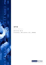
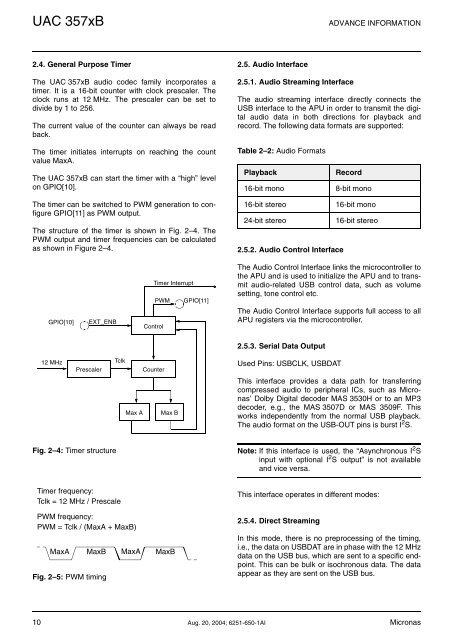
The structure of the timer is shown in Fig. 2–4. The<br />
PWM output and timer frequencies can be calculated<br />
as shown in Figure 2–4.<br />
16-bit stereo<br />
16-bit mono<br />
24-bit stereo<br />
16-bit stereo<br />
2.5.2. Audio Control Interface<br />
GPIO[10]<br />
EXT_ENB<br />
Timer Interrupt<br />
PWM GPIO[11]<br />
Control<br />
The Audio Control Interface links the microcontroller to<br />
the APU and is used to initialize the APU and to transmit<br />
audio-related USB control data, such as volume<br />
setting, tone control etc.<br />
The Audio Control Interface supports full access to all<br />
APU registers via the microcontroller.<br />
2.5.3. Serial Data Output<br />
12 MHz<br />
Prescaler<br />
Tclk<br />
Counter<br />
Used Pins: USBCLK, USBDAT<br />
Max A<br />
Max B<br />
This interface provides a data path for transferring<br />
<strong>com</strong>pressed audio to peripheral ICs, such as Micronas’<br />
Dolby Digital decoder MAS 3530H or to an MP3<br />
decoder, e.g., the MAS 3507D or MAS 3509F. This<br />
works independently from the normal USB playback.<br />
The audio format on the USB-OUT pins is burst I 2 S.<br />
Fig. 2–4: Timer structure<br />
Note: If this interface is used, the “Asynchronous I 2 S<br />
input with optional I 2 S output” is not available<br />
and vice versa.<br />
Timer frequency:<br />
Tclk = 12 MHz / Prescale<br />
PWM frequency:<br />
PWM = Tclk / (MaxA + MaxB)<br />
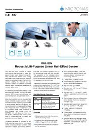
MaxA MaxB MaxA MaxB<br />
Fig. 2–5: PWM timing<br />
This interface operates in different modes:<br />
2.5.4. Direct Streaming<br />
In this mode, there is no preprocessing of the timing,<br />
i.e., the data on USBDAT are in phase with the 12 MHz<br />
data on the USB bus, which are sent to a specific endpoint.<br />
This can be bulk or isochronous data. The data<br />
appear as they are sent on the USB bus.<br />
10 Aug. 20, 2004; 6251-650-1AI Micronas