
Create successful ePaper yourself
Turn your PDF publications into a flip-book with our unique Google optimized e-Paper software.
ADVANCE INFORMATION<br />
<strong>UAC</strong> <strong>357xB</strong><br />
6. <strong>UAC</strong> <strong>357xB</strong> Applications<br />
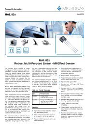
6.1. Re<strong>com</strong>mended Low-Pass Filters for Analog<br />
Outputs<br />
6.2. External Clocking via XTI<br />
AC-coupling of the clock signal<br />
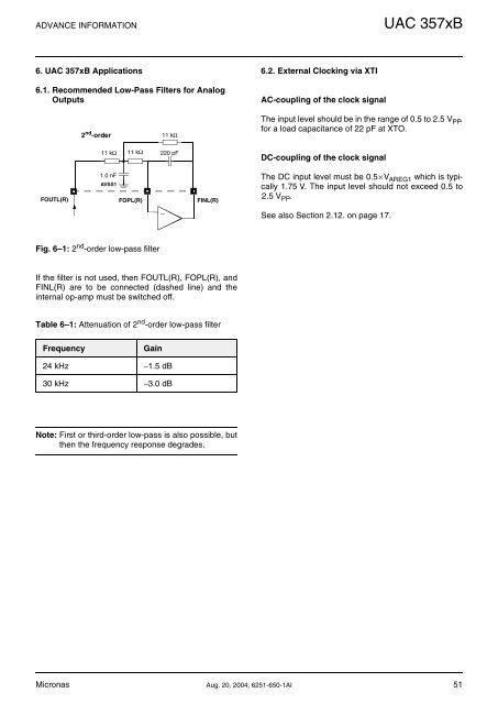
2 nd -order<br />
11 kΩ<br />
The input level should be in the range of 0.5 to 2.5 V PP .<br />
for a load capacitance of 22 pF at XTO.<br />
11 kΩ 11 kΩ<br />
220 pF<br />
DC-coupling of the clock signal<br />
FOUTL(R)<br />
1.0 nF<br />
AVSS1<br />
FOPL(R)<br />
FINL(R)<br />
The DC input level must be 0.5×V AREG1 which is typically<br />
1.75 V. The input level should not exceed 0.5 to<br />
2.5 V PP .<br />
−<br />
See also Section 2.12. on page 17.<br />
Fig. 6–1: 2 nd -order low-pass filter<br />
If the filter is not used, then FOUTL(R), FOPL(R), and<br />
FINL(R) are to be connected (dashed line) and the<br />
internal op-amp must be switched off.<br />
Table 6–1: Attenuation of 2 nd -order low-pass filter<br />
Frequency<br />
Gain<br />
24 kHz −1.5 dB<br />
30 kHz −3.0 dB<br />
Note: First or third-order low-pass is also possible, but<br />
then the frequency response degrades.<br />
Micronas Aug. 20, 2004; 6251-650-1AI 51