
You also want an ePaper? Increase the reach of your titles
YUMPU automatically turns print PDFs into web optimized ePapers that Google loves.
<strong>UAC</strong> <strong>357xB</strong><br />
ADVANCE INFORMATION<br />
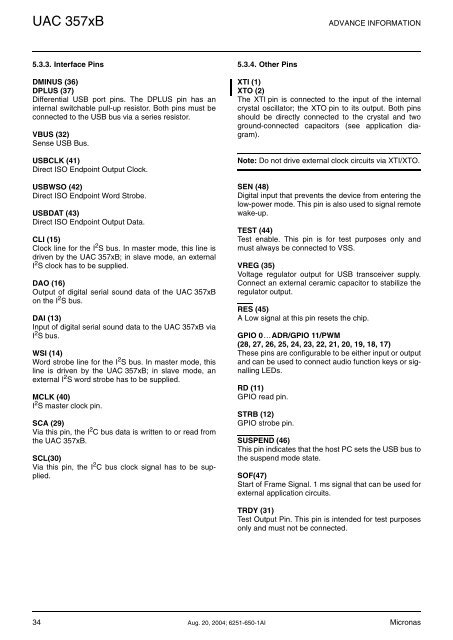
5.3.3. Interface Pins<br />
DMINUS (36)<br />
DPLUS (37)<br />
Differential USB port pins. The DPLUS pin has an<br />
internal switchable pull-up resistor. Both pins must be<br />
connected to the USB bus via a series resistor.<br />
VBUS (32)<br />
Sense USB Bus.<br />
USBCLK (41)<br />
Direct ISO Endpoint Output Clock.<br />
USBWSO (42)<br />
Direct ISO Endpoint Word Strobe.<br />
USBDAT (43)<br />
Direct ISO Endpoint Output Data.<br />
CLI (15)<br />
Clock line for the I 2 S bus. In master mode, this line is<br />
driven by the <strong>UAC</strong> <strong>357xB</strong>; in slave mode, an external<br />
I 2 S clock has to be supplied.<br />
DAO (16)<br />
Output of digital serial sound data of the <strong>UAC</strong> <strong>357xB</strong><br />
on the I 2 S bus.<br />
DAI (13)<br />
Input of digital serial sound data to the <strong>UAC</strong> <strong>357xB</strong> via<br />
I 2 S bus.<br />
WSI (14)<br />
Word strobe line for the I 2 S bus. In master mode, this<br />
line is driven by the <strong>UAC</strong> <strong>357xB</strong>; in slave mode, an<br />
external I 2 S word strobe has to be supplied.<br />
MCLK (40)<br />
I 2 S master clock pin.<br />
SCA (29)<br />
Via this pin, the I 2 C bus data is written to or read from<br />
the <strong>UAC</strong> <strong>357xB</strong>.<br />
SCL(30)<br />
Via this pin, the I 2 C bus clock signal has to be supplied.<br />
5.3.4. Other Pins<br />
XTI (1)<br />
XTO (2)<br />
The XTI pin is connected to the input of the internal<br />
crystal oscillator; the XTO pin to its output. Both pins<br />
should be directly connected to the crystal and two<br />
ground-connected capacitors (see application diagram).<br />
Note: Do not drive external clock circuits via XTI/XTO.<br />
SEN (48)<br />
Digital input that prevents the device from entering the<br />
low-power mode. This pin is also used to signal remote<br />
wake-up.<br />
TEST (44)<br />
Test enable. This pin is for test purposes only and<br />
must always be connected to VSS.<br />
VREG (35)<br />
Voltage regulator output for USB transceiver supply.<br />
Connect an external ceramic capacitor to stabilize the<br />
regulator output.<br />
RES (45)<br />
A Low signal at this pin resets the chip.<br />
GPIO 0…ADR/GPIO 11/PWM<br />
(28, 27, 26, 25, 24, 23, 22, 21, 20, 19, 18, 17)<br />
These pins are configurable to be either input or output<br />
and can be used to connect audio function keys or signalling<br />
LEDs.<br />
RD (11)<br />
GPIO read pin.<br />
STRB (12)<br />
GPIO strobe pin.<br />
SUSPEND (46)<br />
This pin indicates that the host PC sets the USB bus to<br />
the suspend mode state.<br />
SOF(47)<br />
Start of Frame Signal. 1 ms signal that can be used for<br />
external application circuits.<br />
TRDY (31)<br />
Test Output Pin. This pin is intended for test purposes<br />
only and must not be connected.<br />
34 Aug. 20, 2004; 6251-650-1AI Micronas