
Create successful ePaper yourself
Turn your PDF publications into a flip-book with our unique Google optimized e-Paper software.
ADVANCE INFORMATION<br />
<strong>UAC</strong> <strong>357xB</strong><br />
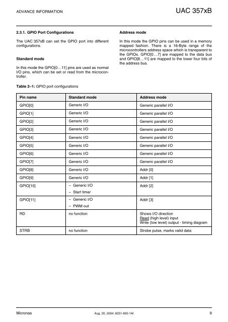
2.3.1. GPIO Port Configurations<br />
The <strong>UAC</strong> <strong>357xB</strong> can set the GPIO port into different<br />
configurations.<br />
Standard mode<br />
In this mode the GPIO[0…11] pins are used as normal<br />
I/O pins, which can be set or read from the microcontroller.<br />
Address mode<br />
In this mode the GPIO pins can be used in a memory<br />
mapped fashion. There is a 16-Byte range of the<br />
microcontrollers address space which is transparent to<br />
the GPIOs. GPIO[0…7] are mapped to the data bus<br />
and GPIO[8…11] are mapped to the lower four bits of<br />
the address bus.<br />
Table 2–1: GPIO port configurations<br />
Pin name Standard mode Address mode<br />
GPIO[0] Generic I/O Generic parallel I/O<br />
GPIO[1] Generic I/O Generic parallel I/O<br />
GPIO[2] Generic I/O Generic parallel I/O<br />
GPIO[3] Generic I/O Generic parallel I/O<br />
GPIO[4] Generic I/O Generic parallel I/O<br />
GPIO[5] Generic I/O Generic parallel I/O<br />
GPIO[6] Generic I/O Generic parallel I/O<br />
GPIO[7] Generic I/O Generic parallel I/O<br />
GPIO[8] Generic I/O Addr [0]<br />
GPIO[9] Generic I/O Addr [1]<br />
GPIO[10]<br />
GPIO[11]<br />
– Generic I/O<br />
– Start timer<br />
– Generic I/O<br />
– PWM out<br />
Addr [2]<br />
Addr [3]<br />
RD no function Shows I/O direction<br />
Read (high level) input<br />
Write (low level) output - timing diagram<br />
STRB no function Strobe pulse, marks valid data<br />
Micronas Aug. 20, 2004; 6251-650-1AI 9