
Create successful ePaper yourself
Turn your PDF publications into a flip-book with our unique Google optimized e-Paper software.
ADVANCE INFORMATION<br />
<strong>UAC</strong> <strong>357xB</strong><br />
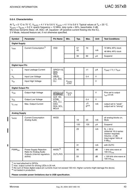
5.6.4. Characteristics<br />
At T A =0°C to 70 °C, V SUPD = 4.1 V to 5.6 V, V SUPA = 4.1 V to 5.6 V. Typical values at T A =20°C,<br />
V SUPD =V SUPA = 5.0 V, quartz frequency = 12 MHz, duty cycle = 50%, bass/treble: 0 dB,<br />
Micronas Dynamic Bass: off, AGC: off, equalizer: off (positive current flowing into the IC),<br />
3 V Mode, reduced feature set, if not otherwise specified.<br />
Symbol Parameter Pin Name Min. Typ. Max. Unit Test Conditions<br />
Digital Supply<br />
I VDD Current Consumption 1) VDD 57<br />
45<br />
70<br />
mA<br />
72 MHz APU clock<br />
48 MHz APU clock<br />
30 80 µA Suspend<br />
Digital Input Pin<br />
I I Input Leakage Current GPIO[11:0],<br />
±1 µA V GND ≤ V I ≤ V SUP<br />
V IL Input Low Voltage<br />
SEN,<br />
RES,<br />
VBUS,<br />
0.4 V<br />
DAI, WSI,<br />
V IH Input High Voltage CLI V SUPD<br />
V<br />
−0.4V<br />
Digital Output Pin<br />
V OH Output High Voltage GPIO[11:0]<br />
SUSPEND,<br />
SOF, RD,<br />
STRB,<br />
WSI, CLI,<br />
V SUPD<br />
− 0.4<br />
V OL Output Low Voltage 0.4 V<br />
I O_max Max. Output Current DAO,<br />
1 3)<br />
SDA, SCL,<br />
8 2)3)<br />
MCLK<br />
V<br />
mA<br />
Pins set to output<br />
I out =8 mA<br />
output set to “weak”<br />
output set to “strong”<br />
Analog Supply<br />
I AVDD<br />
Current Consumption<br />
Analog Audio<br />
AVDD<br />
18 23 mA<br />
all analog blocks on,<br />
Mute<br />
120 135 µA Suspend<br />
29 mA R L ≥ 32 Ω<br />
(external 16 Ω series<br />
resistor required)<br />
Volume = 0 dB,<br />
Input signal 1kHz at<br />
0dB FS<br />
31 mA with OUTC<br />
PSRR AA<br />
Power Supply Rejection<br />
Ratio for Analog Audio<br />
Outputs (internal regulators<br />
active)<br />
AVDD, 4)<br />
OUTL/R/S<br />
95 dB 1 kHz sine wave at<br />
100 mV rms<br />
55 dB ≤ 100 kHz sine wave at<br />
100 mV rms<br />
1) no load attached to GPIOs.<br />
2) max. output current for driving LEDs is 20 mA.<br />
3) the sum of these digital output pin currents must not exceed 100 mA. Higher currents might damage the device.<br />
4) not tested in production.<br />
Please consider power limitations due to USB specification.<br />
Micronas Aug. 20, 2004; 6251-650-1AI 43