
You also want an ePaper? Increase the reach of your titles
YUMPU automatically turns print PDFs into web optimized ePapers that Google loves.
ADVANCE INFORMATION<br />
<strong>UAC</strong> <strong>357xB</strong><br />
2.5.5. Microcontroller Streaming<br />
In this mode, the microcontroller copies the data from<br />
the RAM to a shift register, which is connected to the<br />
USBDAT pin. The shift clock can be programmed<br />
between 6 MHz and 750 kHz and appears on USB-<br />
CLK pin.<br />
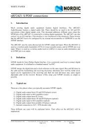
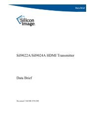
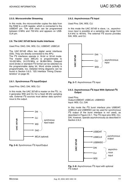
2.6.2. Asynchronous I 2 S Input<br />
Used Pins: DAI, WSI, CLI<br />
In this mode the <strong>UAC</strong> <strong>357xB</strong> is slave, i.e., asynchronous<br />
input is possible at a sampling rate range from<br />
6.4 kHz to 48 kHz. The external I 2 S source provides<br />
DAI, WSI, and CLI<br />
2.6. The <strong>UAC</strong> <strong>357xB</strong> Serial Audio Interfaces<br />
Used Pins: DAO, DAI, WSI, CLI, USBDAT, USBCLK<br />
The <strong>UAC</strong> <strong>357xB</strong> offers two digital serial interfaces<br />
(I2S). They are directly connected to the APU.<br />
The I 2 S interfaces operate in 16-bit or 32-bit mode.<br />
The master clock (MCLK) is programmable to<br />
18.432 MHz, 24.576 MHz or 36.864 MHz. Delayed<br />
word strobe or standard I 2 S format can be selected via<br />
the programmable delay bit. Word strobe polarity is<br />
programmable, too. Detailed timing diagrams can be<br />
found in Section 5.6.5. “I2S Interface Timing Characteristics”<br />
on page 49.<br />
<strong>UAC</strong> <strong>357xB</strong><br />
DAI<br />
CLI<br />
WSI<br />
asynchronous<br />
input<br />
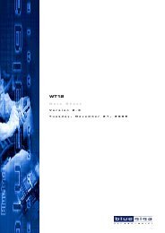
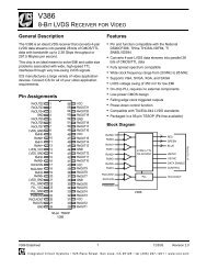
2.6.1. Synchronous I 2 S Input/Output<br />
Used Pins: DAO, DAI, WSI, CLI<br />
In this mode, the <strong>UAC</strong> <strong>357xB</strong> is master on the I 2 S, i.e,<br />
it generates WSI and CLI for a fixed 48 kHz sampling<br />
rate. External I 2 S sources must deliver data synchronous<br />
to the output.<br />
Fig. 2–7: Asynchronous I 2 S input<br />
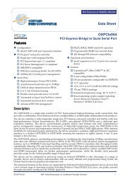
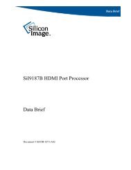
2.6.3. Asynchronous I 2 S Input With Optional I 2 S<br />
Output<br />
Used Pins:<br />
Output:USBDAT, USBCLK, USBWSO<br />
Input: WSI, CLI, DAI<br />
<strong>UAC</strong> <strong>357xB</strong><br />
DAI<br />
CLI<br />
WSI<br />
DAO<br />
synchronous<br />
input/output<br />
In this mode the I 2 S burst interface pins USBDAT,<br />
USBCLK and USBWSO can be used for synchronous<br />
I 2 S output (if the burst interface is not used), as<br />
described in Figure 2.6.1. The I 2 S input pins WSI, CLI,<br />
DAI, however, operate asynchronously as described in<br />
Section 2.6.2.<br />
USBDAT<br />
MCLK (optional)<br />
Fig. 2–6: Synchronous I 2 S Input/Output<br />
<strong>UAC</strong> <strong>357xB</strong><br />
USBCLK<br />
USBWSO<br />
DAI<br />
CLI<br />
WSI<br />
synchronous<br />
output<br />
asynchronous<br />
input<br />
Fig. 2–8: Asynchronous I 2 S input with optional<br />
I 2 S output<br />
Micronas Aug. 20, 2004; 6251-650-1AI 11