SX1243 - Semtech
SX1243 - Semtech
SX1243 - Semtech

You also want an ePaper? Increase the reach of your titles
YUMPU automatically turns print PDFs into web optimized ePapers that Google loves.
<strong>SX1243</strong><br />
WIRELESS & SENSING<br />
<strong>SX1243</strong> - Low Cost Low Current Integrated Transmitter<br />
310 to 928MHz Frequency Agile<br />
DATASHEET<br />
GENERAL DESCRIPTION<br />
The <strong>SX1243</strong> is an ultra-low-cost, fully integrated FSK or<br />
OOK transmitter suitable for operation between 310 and<br />
450 MHz, 860 and 870 MHz, as well as 902 and 928 MHz.<br />
For applications where economy is paramount, the <strong>SX1243</strong><br />
may be used without the requirement for configuration via<br />
an MCU. However, in conjunction with a microcontroller the<br />
communication link parameters may be re-configured.<br />
Including, output power, modulation format and operating<br />
channel.<br />
The <strong>SX1243</strong> offers integrated radio performance with cost<br />
efficiency and is suited for operation in North America FCC<br />
Part 15.231, FCC Part 15.247 FHSS and Digital Modulation<br />
Techniques, 15.249, and Europe EN 300 220.<br />
ORDERING INFORMATION<br />
Part Number Temperature Range Package MOQ / Multiple<br />
<strong>SX1243</strong>IULTRT -40 °C to +85 °C DFN-UT8 3000 pieces<br />
Pb-Free, Halogen Free, RoHS/WEEE compliant product.<br />
APPLICATIONS<br />
• Garage Door Openers<br />
• Low-Cost Consumer Electronic Applications<br />
• Remote Keyless Entry (RKE)<br />
• Remote Control / Security Systems<br />
KEY PRODUCT FEATURES<br />
• +10 dBm or 0 dBm Configurable output power<br />
• Bit rates up to 100 kbps<br />
• OOK and FSK modulation.<br />
• 1.8 to 3.7 V supply range.<br />
• Low BOM Fully Integrated Tx<br />
• Fractional-N PLL with 1.5 kHz typical step<br />
• Frequency agility for FHSS modulation<br />
• FCC CFR Part 15.247 Digital Modulation Techniques<br />
NRESET<br />
1<br />
8<br />
RFOUT<br />
PA<br />
DATA<br />
2<br />
CP<br />
M/N<br />
7<br />
TX_READY<br />
GND<br />
3<br />
PFD<br />
6<br />
CTRL<br />
XTAL<br />
4<br />
Sigma<br />
/Delta<br />
5<br />
VDD<br />
1.8 to 3.7 V<br />
Revision 4 - February 2013<br />
©2013 <strong>Semtech</strong> Corporation<br />
Page 1<br />
www.semtech.com
<strong>SX1243</strong><br />
WIRELESS & SENSING<br />
Table of contents<br />
Section<br />
DATASHEET<br />
Page<br />
1. Circuit Description ....................................................................................................................................................................... 3<br />
1.1. General Description ............................................................................................................................................................ 3<br />
1.2. Block Diagram .................................................................................................................................................................... 3<br />
1.3. Marking Diagram ................................................................................................................................................................ 4<br />
1.4. Pin Description, DFN8 Encapsulation ..................................................................................................................................... 5<br />
2. Electrical Characteristics ............................................................................................................................................................. 6<br />
2.1. ESD Notice ......................................................................................................................................................................... 6<br />
2.2. Absolute Maximum Ratings ................................................................................................................................................ 6<br />
2.3. Operating Range ................................................................................................................................................................ 6<br />
2.4. Electrical Specifications ........................................................................................................................................................... 7<br />
3. Digital Specification ..................................................................................................................................................................... 9<br />
4. Application Modes of the <strong>SX1243</strong> ............................................................................................................................................. 10<br />
4.1. Transmitter Modes............................................................................................................................................................ 10<br />
4.2. Mode Selection Flowchart ................................................................................................................................................ 11<br />
4.3. Application Mode: Power & Go ............................................................................................................................................. 12<br />
4.4. Application Mode: Advanced ............................................................................................................................................ 12<br />
4.4.1. Advanced Mode: Configuration................................................................................................................................. 12<br />
4.4.2. Frequency Hopping Spread Spectrum...................................................................................................................... 12<br />
4.5. Frequency Band Coverage ................................................................................................................................................... 13<br />
4.6. Power Consumption .............................................................................................................................................................. 14<br />
5. <strong>SX1243</strong> Configuration ............................................................................................................................................................... 15<br />
5.1. TWI Access....................................................................................................................................................................... 15<br />
5.2. APPLICATION Configuration Parameters ........................................................................................................................ 17<br />
5.3. FREQUENCY Configuration Parameters ......................................................................................................................... 17<br />
5.4. Test Parameters ............................................................................................................................................................... 18<br />
5.5. Status Parameters ............................................................................................................................................................ 18<br />
5.6. Recovery Command .............................................................................................................................................................. 19<br />
6. Application Information.............................................................................................................................................................. 20<br />
6.1. Crystal Specification ......................................................................................................................................................... 20<br />
6.2. Evaluation Module ............................................................................................................................................................ 20<br />
6.3. NRESET Pin ..................................................................................................................................................................... 22<br />
6.4. TX_READY Pin................................................................................................................................................................. 22<br />
6.5. Low Power Optimization ................................................................................................................................................... 22<br />
6.5.1. 2 Connections: CTRL, DATA .................................................................................................................................... 22<br />
6.5.2. 3 Connections: CTRL, DATA, TX_READY ............................................................................................................... 22<br />
7. <strong>SX1243</strong> Packaging.................................................................................................................................................................... 23<br />
7.1. Package Outline Drawing ................................................................................................................................................. 23<br />
7.2. Thermal Impedance.......................................................................................................................................................... 23<br />
7.3. Land Pattern ..................................................................................................................................................................... 24<br />
7.4. Tape & Reel Specification ................................................................................................................................................ 24<br />
8. Revision History ........................................................................................................................................................................ 25<br />
Revision 4 - February 2013<br />
©2013 <strong>Semtech</strong> Corporation<br />
Page 2<br />
www.semtech.com
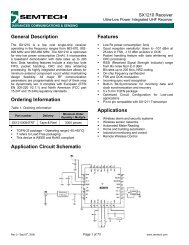
WIRELESS & SENSING<br />
<strong>SX1243</strong><br />
Integrated Transmitter IC<br />
DATASHEET<br />
This product datasheet contains a detailed description of the <strong>SX1243</strong> performance and functionality.<br />
1. Circuit Description<br />
1.1. General Description<br />
The <strong>SX1243</strong> is a fully-integrated multi-band, single chip transmitter IC capable of FSK and OOK modulation of an input<br />
data stream.<br />
It contains a frequency synthesizer which is a fractional-N sigma-delta PLL. For frequency modulation (FSK), the<br />
modulation is made inside the PLL bandwidth. For amplitude modulation (OOK), the modulation is performed by turning on<br />
and off the output PA.<br />
The frequency reference used by the PLL is generated by a 22, 24 or 26 MHz crystal oscillator, depending on the<br />
frequency band of interest.<br />
The Power Amplifier (PA), connected to the RFOUT pin, can deliver 0 dBm or +10 dBm in a 50 Ω load. Each of these two<br />
output powers need a specific matching network when efficiency needs to be optimized.<br />
The circuit can be configured via a simplified TWI interface, constituted of pin CTRL and DATA. The pins of this interface<br />
are also used to transmit the modulating data to the chip.<br />
Another key feature of the <strong>SX1243</strong> is its low current consumption in Transmit and Sleep modes and its wide voltage<br />
operating range from 1.8 V to 3.7 V. This makes the <strong>SX1243</strong> suitable for low-cost battery chemistries or energy harvesting<br />
applications.<br />
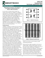
1.2. Block Diagram<br />
The figure below shows the simplified block diagram of the <strong>SX1243</strong> die mounted in a DFN8 package.<br />
NRESET<br />
1<br />
8<br />
RFOUT<br />
PA<br />
DATA<br />
2<br />
CP<br />
M/N<br />
7<br />
TX_READY<br />
GND<br />
3<br />
PFD<br />
6<br />
CTRL<br />
XTAL<br />
4<br />
Sigma<br />
/Delta<br />
5<br />
VDD<br />
1.8 to 3.7 V<br />
Figure 1. <strong>SX1243</strong> Simplified Block Diagram and BOM<br />
Revision 4 - February 2013<br />
©2013 <strong>Semtech</strong> Corporation<br />
Page 3<br />
www.semtech.com
WIRELESS & SENSING<br />
<strong>SX1243</strong><br />
Integrated Transmitter IC<br />
DATASHEET<br />
1.3. Marking Diagram<br />
Figure 2. Marking Diagram<br />
- nnn = Relates to the part number<br />
- yw = Date code<br />
- xxx = Lot No<br />
Revision 4 - February 2013<br />
©2013 <strong>Semtech</strong> Corporation<br />
Page 4<br />
www.semtech.com
WIRELESS & SENSING<br />
<strong>SX1243</strong><br />
Integrated Transmitter IC<br />
DATASHEET<br />
1.4. Pin Description, DFN8 Encapsulation<br />
Table 1 Description of the <strong>SX1243</strong> DFN8 Pinouts<br />
Number Name Type Function in ‘Power & Go’ Modes Function in ‘Advanced’ Mode<br />
0 GND I Exposed Pad, Ground<br />
1 NRESET I Reset (Optional, can be left floating)<br />
2 DATA I/O Transmit Data Transmit or Configuration Data<br />
3 GND I Ground<br />
4 XTAL I/O Reference Crystal<br />
5 VBAT I Power Supply 1.8V to 3.7V<br />
6 CTRL I Config Selection Configuration Data Clock<br />
7 TX_READY O Transmitter Ready Flag (Optional, can be left floating)<br />
8 RFOUT O Transmitter RF Output<br />
Revision 4 - February 2013<br />
©2013 <strong>Semtech</strong> Corporation<br />
Page 5<br />
www.semtech.com
WIRELESS & SENSING<br />
<strong>SX1243</strong><br />
Integrated Transmitter IC<br />
DATASHEET<br />
2. Electrical Characteristics<br />
2.1. ESD Notice<br />
The <strong>SX1243</strong> is an electrostatic discharge sensitive device. It satisfies Class 2 of the JEDEC standard<br />
JESD22-A114-B (Human Body Model) on all pins.<br />
2.2. Absolute Maximum Ratings<br />
Stresses above the values listed below may cause permanent device failure. Exposure to absolute maximum ratings for<br />
extended periods may affect device reliability.<br />
Table 2<br />
Absolute Maximum Ratings<br />
Symbol Description Min Max Unit<br />
VDDmr Supply Voltage -0.5 3.9 V<br />
Tmr Temperature -55 115 ° C<br />
Tjunc Junction Temperature -55 125 ° C<br />
Tstor Storage Temperature -55 150 ° C<br />
2.3. Operating Range<br />
Operating ranges define the limits for functional operation and the parametric characteristics of the device as described in<br />
this section. Functionality outside these limits is not implied.<br />
Table 3<br />
Operating Range<br />
Symbol Description Min Max Unit<br />
VDDop Supply voltage 1.8 3.7 V<br />
Top Operational temperature range -40 85 ° C<br />
Clop Load capacitance on digital ports - 25 pF<br />
Revision 4 - February 2013<br />
©2013 <strong>Semtech</strong> Corporation<br />
Page 6<br />
www.semtech.com
WIRELESS & SENSING<br />
<strong>SX1243</strong><br />
Integrated Transmitter IC<br />
DATASHEET<br />
2.4. Electrical Specifications<br />
The table below gives the electrical specifications of the transmitter under the following conditions: Supply voltage VBAT =<br />
3.3 V, temperature = 25 °C, f XOSC = 26 MHz, f RF = 915 MHz, 2-FSK modulation with Fdev=+/-10 kHz, bit rate = 10 kbit/s<br />
and output power = +10 dBm terminated in a matched 50 Ohm impedance, unless otherwise specified.<br />
Table 4 Transmitter Specifications<br />
Symbol Description Conditions Min Typ Max Unit<br />
Current Consumption<br />
IDDSL Supply current in Sleep mode - 125 nA<br />
IDDT_315<br />
Supply current in Transmit mode<br />
at 315 MHz*<br />
RFOP=+10dBm 50% OOK<br />
RFOP=+10dBm FSK<br />
RFOP=0dBm FSK<br />
-<br />
-<br />
-<br />
11<br />
15<br />
9<br />
-<br />
-<br />
-<br />
mA<br />
mA<br />
mA<br />
IDDT_915<br />
Supply current in Transmit mode<br />
at 915 MHz*<br />
RFOP=+10dBm FSK<br />
RFOP=0dBm FSK<br />
-<br />
-<br />
17.5<br />
10.5<br />
-<br />
-<br />
mA<br />
mA<br />
RF and Baseband Specifications<br />
FBAND<br />
Accessible Frequency Bands<br />
See details in Table 7.<br />
Band 0, with FXOSC=22 MHz 310 - 450 MHz<br />
Band 0, with FXOSC=24 MHz 312 - 450 MHz<br />
Band 0, with FXOSC=26 MHz 338 - 450 MHz<br />
Band 1, with FXOSC=26 MHz 860<br />
902<br />
-<br />
-<br />
870<br />
928<br />
MHz<br />
MHz<br />
FDA Frequency deviation, FSK 10 - 200 kHz<br />
BRF Bit rate, FSK Permissible Range 0.5 - 100 kbps<br />
BRO Bit rate, OOK Permissible Range 0.5 - 10 kbps<br />
OOK_B OOK Modulation Depth - 45 - dB<br />
RFOP<br />
RF output power in 50 Ohms<br />
in either frequency band<br />
High Power Setting<br />
Low Power Setting*<br />
7<br />
-3<br />
10<br />
0<br />
-<br />
-<br />
dBm<br />
dBm<br />
RFOPFL RF output power flatness From 315 to 390 MHz, 50 Ohms load - 2 - dB<br />
DRFOPV<br />
Variation in RF output power with<br />
supply voltage<br />
2.5 V to 3.3 V<br />
1.8 V to 3.7 V<br />
-<br />
-<br />
-<br />
-<br />
3<br />
7<br />
dB<br />
dB<br />
PHN Transmitter phase noise At offset: 100 kHz<br />
350 kHz<br />
550 kHz<br />
1.15 MHz<br />
-<br />
-<br />
-<br />
-<br />
-84<br />
-94<br />
-96<br />
-105<br />
-<br />
-<br />
-<br />
-<br />
dBc/Hz<br />
dBc/Hz<br />
dBc/Hz<br />
dBc/Hz<br />
STEP_22 RF frequency step FXOSC = 22 MHz, Band 0 - 1.34277 - kHz<br />
STEP_24 RF frequency step FXOSC = 24 MHz, Band 0 - 1.46484 - kHz<br />
STEP_26 RF frequency step FXOSC = 26 MHz, Band 0<br />
FXOSC = 26 MHz, Band 1<br />
-<br />
-<br />
1.58691<br />
3.17383<br />
-<br />
-<br />
kHz<br />
kHz<br />
Revision 4 - February 2013<br />
©2013 <strong>Semtech</strong> Corporation<br />
Page 7<br />
www.semtech.com
WIRELESS & SENSING<br />
<strong>SX1243</strong><br />
Integrated Transmitter IC<br />
DATASHEET<br />
Symbol Description Conditions Min Typ Max Unit<br />
FXOSC Crystal Oscillator Frequency -<br />
-<br />
-<br />
22<br />
24<br />
26<br />
-<br />
-<br />
-<br />
MHz<br />
MHz<br />
MHz<br />
DFXOSC Frequency Variation of the XOSC No crystal contribution - - +/-25 ppm<br />
Timing Specifications<br />
TS_TR Time from Sleep to Tx mode XTAL dependant, with spec’d XTAL - 650 2000 us<br />
TS_HOP0 Channel hop time in Band 0 315 to 390 MHz - 250 500 us<br />
TS_HOP1 Channel hop time in Band 1 Maximum hop of 26 MHz*** - 200 400 us<br />
TOFFT<br />
Timer from Tx data activity to<br />
Sleep<br />
Programmable -<br />
-<br />
2<br />
20<br />
-<br />
-<br />
ms<br />
ms<br />
RAMP PA Ramp up and down time - 20 - us<br />
T_START<br />
Time before CTRL pin mode<br />
selection.<br />
Time from power on to sampling of<br />
CTRL **<br />
- 200 us<br />
+ TS_OSC<br />
- ms<br />
* With different matching networks<br />
** The oscillator startup time, TS_OSC, depends on the electrical characteristics of the crystal<br />
*** From the last CTRL falling edge of the Frequency change instruction to transmitter ready (PA ramp up finished)<br />
Revision 4 - February 2013<br />
©2013 <strong>Semtech</strong> Corporation<br />
Page 8<br />
www.semtech.com
WIRELESS & SENSING<br />
<strong>SX1243</strong><br />
Integrated Transmitter IC<br />
DATASHEET<br />
3. Digital Specification<br />
The following table gives the operating specifications for the digital inputs and outputs of the <strong>SX1243</strong>.<br />
Table 5<br />
Digital Signals Specification<br />
Symbol Description Conditions Min Typ Max Unit<br />
V IH Digital input level high 0.8 - - VBAT<br />
V IL Digital input level low - - 0.2 VBAT<br />
V OH Digital output level high Imax = 1 mA 0.9 - - VBAT<br />
V OL Digital output level low Imax = -1 mA - - 0.1 VBAT<br />
f CTRL CTRL Clock Frequency - - 10 MHz<br />
t ch CTRL Clock High time 45 - - ns<br />
t cl CTRL Clock Low time 45 - - ns<br />
t rise CTRL Clock rise time - - 5 ns<br />
t fall CTRL Clock Fall time - - 5 ns<br />
t setup DATA Setup time From Data transition to CTRL rising<br />
edge<br />
t hold DATA hold time From CTRL rising edge to DATA<br />
transition<br />
45 - - ns<br />
45 - - ns<br />
t 0 , t 2<br />
t 1<br />
Time at “1” on DATA during<br />
Recovery command<br />
Time at “0” on DATA during<br />
Recovery command<br />
See Figure 10 and Figure 11 - - 5 us<br />
See Figure 11 5 - - us<br />
Revision 4 - February 2013<br />
©2013 <strong>Semtech</strong> Corporation<br />
Page 9<br />
www.semtech.com
WIRELESS & SENSING<br />
<strong>SX1243</strong><br />
Integrated Transmitter IC<br />
DATASHEET<br />
4. Application Modes of the <strong>SX1243</strong><br />
Pins CTRL and DATA are used for both configuring the circuit and sending the data to be transmitted over the air. Two<br />
different modes are associated to these pins, “Power&Go” and “Advanced” modes.<br />
4.1. Transmitter Modes<br />
Automatic Mode operation is described in Figure 3. Here we see that a rising edge on the DATA pin activates the<br />
transmitter start-up process. DATA must be held high for the start-up time (TS_TR) of the <strong>SX1243</strong>. During this time the<br />
<strong>SX1243</strong> undergoes an optimized, self-calibrating trajectory from Sleep mode to Transmit mode. Once this time has<br />
elapsed, the <strong>SX1243</strong> is ready to transmit. Any logical signal subsequently applied to the DATA pin is then transmitted.<br />
Figure 3. ‘Power & Go’ Mode: Transmitter Timing Operation<br />
The transition back to Sleep mode is managed automatically. The <strong>SX1243</strong> waits for TOFFT (2 or 20 ms) of inactivity on<br />
DATA before returning to Sleep mode.<br />
In Forced Transmit Mode the circuit can be forced to wake up and go to TX mode by sending an APPLICATION<br />
instruction through the TWI interface, and setting the Mode bit DA(15) to ‘1’. Once in Transmit the circuit will transmit over<br />
the air the data stream presented on the DATA pin. The circuit will stay in transmit mode until a new APPLICATION<br />
instruction is sent with DA(15) to ‘0’.<br />
Figure 4. Forced Transmit Mode Description<br />
Revision 4 - February 2013<br />
©2013 <strong>Semtech</strong> Corporation<br />
Page 10<br />
www.semtech.com
WIRELESS & SENSING<br />
<strong>SX1243</strong><br />
Integrated Transmitter IC<br />
DATASHEET<br />
4.2. Mode Selection Flowchart<br />
Circuit Start-up<br />
Wait T_Start<br />
Check<br />
Logic ‘0’ CTRL Pin<br />
Logic ‘1’<br />
Power & Go 1<br />
868.3 MHz<br />
FSK, Fdev=+/-19.2kHz<br />
+10dBm<br />
Power & Go 2<br />
433.92 MHz<br />
OOK<br />
+10dBm<br />
CTRL Clock signal<br />
Advanced Mode<br />
Full register flexibility<br />
Automatic or forced Transmit<br />
Figure 5. <strong>SX1243</strong> Mode Selection<br />
Note:<br />
Advanced mode is entered only if DATA is held low during CTRL’s rising edge.<br />
When powering up the circuit (microcontroller and <strong>SX1243</strong>), the logic level of the CTRL pin is sampled after T_START, as<br />
described on Figure 6. During T_START, the microcontroller IO driving the CTRL pin must be configured as an output,<br />
driving the CTRL pin to the desired state.<br />
Figure 6. Power-up Timing<br />
Revision 4 - February 2013<br />
©2013 <strong>Semtech</strong> Corporation<br />
Page 11<br />
www.semtech.com
WIRELESS & SENSING<br />
<strong>SX1243</strong><br />
Integrated Transmitter IC<br />
DATASHEET<br />
4.3. Application Mode: Power & Go<br />
The default ‘Power & Go’ application mode sees the <strong>SX1243</strong> configured as detailed in Table 6. By changing the logical<br />
state of the CTRL pin at Power-up or Reset, two distinct configuration modes can be selected. The Power & Go application<br />
modes hence permit microcontroller-less operation.<br />
Table 6<br />
Configuration in Power & Go Mode<br />
CTRL Pin Configuration Mode<br />
‘Low’ FSK 868.3 MHz, +10 dBm, Fdev=+/-19.2 kHz Power&Go 1<br />
‘High’ OOK 433.92 MHz, +10 dBm Power&Go 2<br />
4.4. Application Mode: Advanced<br />
4.4.1. Advanced Mode: Configuration<br />
As described on Figure 5, Advanced mode is entered when accessing the Two Wire Interface (TWI) bus of the <strong>SX1243</strong>.<br />
Upon communication to the register at up to 10 MHz of clocking speed, complete flexibility on the use of the chip is<br />
obtained.<br />
Once all register settings are selected (see registers detailed description in section [5]), the <strong>SX1243</strong> can be used either in<br />
Automatic mode by simply toggling the DATA pin, or in Forced Transmit mode to optimize timings for instance.<br />
4.4.2. Frequency Hopping Spread Spectrum<br />
Frequency hopping is supported in Advanced mode. After sending the data stream in the first channel, the user can send<br />
a Frequency change instruction containing the new channel frequency. The circuit will automatically ramp down the PA,<br />
lock the PLL to the new frequency, and turn the Power Amplifier back on. The user can then send his packet data on the<br />
new channel. Timings are detailed hereafter:<br />
t < TOFFT<br />
(2 or 20 ms)<br />
TWI<br />
instruction<br />
t < TOFFT<br />
(2 or 20 ms)<br />
DATA<br />
Frequency change<br />
CTRL<br />
Frequency change<br />
RFOUT<br />
5th falling<br />
edge on CTRL<br />
Tx Channel A<br />
24th falling<br />
edge on CTRL<br />
TS_HOP i<br />
Tx Channel B<br />
Figure 7. Frequency Hopping Description<br />
Notes: - During any TWI access, the input of the modulator is inhibited<br />
- The time between two Frequency change instructions shall be greater than TS_HOPi<br />
- FHSS modulation, as described under FCC part 15.247, is supported by the <strong>SX1243</strong>; also note that the large<br />
Frequency Deviation settings available on the <strong>SX1243</strong> make it suitable for “Digitally Modulated Systems”, as<br />
described under FCC Part 15.247 (a)(2)<br />
Revision 4 - February 2013<br />
©2013 <strong>Semtech</strong> Corporation<br />
Page 12<br />
www.semtech.com
WIRELESS & SENSING<br />
<strong>SX1243</strong><br />
Integrated Transmitter IC<br />
DATASHEET<br />
4.5. Frequency Band Coverage<br />
The <strong>SX1243</strong> offers several combinations or frequency references and frequency outputs, allowing for maximum flexibility<br />
and design of multi-band products:<br />
Table 7<br />
Frequency Selection Table<br />
Reference<br />
Frequency<br />
FXOSC<br />
Band Setting<br />
DA(13)<br />
Upper / Lower<br />
Frequency<br />
Bounds<br />
Fstep<br />
Frf &<br />
Fdev<br />
22 MHz<br />
310 to 450 MHz<br />
Fstep=<br />
22x10 6<br />
----------------- = 1.34277kHz<br />
2 14<br />
0<br />
Frf=<br />
DF( 18;<br />
0) × Fstep<br />
24 MHz 312 to 450 MHz<br />
Fstep=<br />
24x10 6<br />
----------------- = 1.46484kHz<br />
2 14<br />
Fdev=<br />
DA( 12;<br />
5) × Fstep<br />
338 to 450 MHz<br />
Fstep=<br />
26x10 6<br />
----------------- = 1.58691kHz<br />
2 14<br />
26 MHz<br />
1<br />
860 to 870 MHz<br />
and<br />
902 to 928 MHz<br />
26x10 6<br />
Fstep=<br />
----------------- = 3.17383kHz<br />
2 13<br />
Revision 4 - February 2013<br />
©2013 <strong>Semtech</strong> Corporation<br />
Page 13<br />
www.semtech.com
WIRELESS & SENSING<br />
<strong>SX1243</strong><br />
Integrated Transmitter IC<br />
DATASHEET<br />
4.6. Power Consumption<br />
The following typical power consumption figures are observed on the <strong>SX1243</strong> kits. Note that the transmitter efficiency<br />
depends on the impedance matching quality, and can be PCB design dependant.<br />
The PA matching may be different in each frequency band.<br />
Table 8<br />
Power Consumption in Tx mode<br />
Frequency Band<br />
Conditions<br />
Typical Current<br />
Drain<br />
310 to 450 MHz Pout=+10dBm, OOK modulation with 50% duty cycle<br />
Pout=+10dBm, FSK modulation<br />
Pout=0dBm, FSK modulation<br />
860 to 870 MHz Pout=+10dBm, FSK modulation<br />
Pout=0dBm, FSK modulation<br />
902 to 928 MHz Pout=+10dBm, FSK modulation<br />
Pout=0dBm, FSK modulation<br />
11 mA<br />
15 mA<br />
9 mA<br />
16.5 mA<br />
10 mA<br />
17.5 mA<br />
10.5 mA<br />
Revision 4 - February 2013<br />
©2013 <strong>Semtech</strong> Corporation<br />
Page 14<br />
www.semtech.com
WIRELESS & SENSING<br />
<strong>SX1243</strong><br />
Integrated Transmitter IC<br />
DATASHEET<br />
5. <strong>SX1243</strong> Configuration<br />
The <strong>SX1243</strong> has several configuration parameters which can be selected through the serial interface.<br />
5.1. TWI Access<br />
As long as CTRL is kept stable, the DATA pin is considered by the circuit as the input for the data to be transmitted over the<br />
air (Power&Go modes).<br />
Programming of the configuration register is triggered by a rising edge on the CTRL line. Upon detection of this rising edge,<br />
the data applied to the DATA pin is accepted as register configuration information, the data bits are clocked on subsequent<br />
rising edges of the clocking signal applied to the CTRL pin. The timing for <strong>SX1243</strong> configuration register ‘write’ is shown in<br />
Figure 8. Note that, once triggered, all 24 clock cycle must be issued to the <strong>SX1243</strong>.<br />
CTRL<br />
DATA<br />
1st 2nd 23rd 24th<br />
DATA pin is an input<br />
Figure 8. TWI Configuration Register ‘Write’.<br />
The registers may, similarly, be read using the timing of Figure 9.<br />
CTRL<br />
DATA<br />
1st 2nd 8th 24th<br />
DATA pin is an output<br />
DATA pin is an input<br />
Figure 9. TWI Configuration Register ‘Read’.<br />
The first rising edge on CTRL which initiates the ADVANCED mode must occur at least 1 ms after the circuit has been<br />
powered up or reset.<br />
Revision 4 - February 2013<br />
©2013 <strong>Semtech</strong> Corporation<br />
Page 15<br />
www.semtech.com
WIRELESS & SENSING<br />
<strong>SX1243</strong><br />
Integrated Transmitter IC<br />
DATASHEET<br />
Table 9<br />
TWI Instruction Table<br />
Byte 0 Byte 1 Byte 2<br />
7 6 5 4 3 2 1 0 7 6 5 4 3 2 1 0 7 6 5 4 3 2 1 0<br />
Instruction<br />
0 0 0 0 (0000) DA(15:0) Write Application bits<br />
0 0 0 1 1 DF(18:0) Write Frequency bits<br />
0 0 1 0 (0)(0010)(0010) DT(10:0) Write Test bits (pad protected)<br />
0 0 1 1 (0011) DA(15:0) Read Application bits<br />
0 1 0 0 (0100) DF(15:0) Read the 16 least significant Frequency bits<br />
0 1 0 1 (0101) DS(12:5) DS(4:0) DF(18:<br />
16)<br />
0 1 1 0 (0110) DS(28:13) Read Bist signature<br />
0 1 1 1 (0111) (1111)(1) DT(10:0) Read Test bits<br />
Read Chip version, Status and 3 most significant<br />
Frequency bits<br />
1 x Discarded, not an instruction<br />
All 1<br />
Recovery instruction<br />
Notes<br />
- The first “0” transmitted to the <strong>SX1243</strong> is required to initialize communication<br />
- The following 3 bits (highlighted in blue) determine the type of instruction<br />
- The forthcoming bits (highlighted in green) define a protection pattern; any error in these bits voids the instruction<br />
Revision 4 - February 2013<br />
©2013 <strong>Semtech</strong> Corporation<br />
Page 16<br />
www.semtech.com
WIRELESS & SENSING<br />
<strong>SX1243</strong><br />
Integrated Transmitter IC<br />
DATASHEET<br />
5.2. APPLICATION Configuration Parameters<br />
Name Number Description<br />
Power<br />
&Go 1<br />
Power<br />
&Go 2<br />
Mode DA(15) Mode:<br />
0 Automatic mode<br />
1 Forced transmit mode<br />
Modul DA(14) Modulation scheme:<br />
0 FSK<br />
1 OOK<br />
Band DA(13) Band 0, 310 to 450 MHz<br />
Band 1, 860 to 870 MHz and 902 to 928 MHz<br />
Fdev DA(12:5) RF Frequency deviation in FSK mode only<br />
See Table 7 for details<br />
0<br />
0 1<br />
1 0<br />
0x06<br />
Fdev=<br />
+/-19.2kHz<br />
Unused<br />
Pout DA(4) Output power range:<br />
0 0 dBm<br />
1 10 dBm<br />
TOFFT DA(3) Period of inactivity on DATA before <strong>SX1243</strong><br />
enters Sleep mode in Automatic mode:<br />
0 2 ms<br />
1 20 ms<br />
1 1<br />
0 1<br />
RES DA(2:0) Reserved 100 100<br />
Table 10 APPLICATION Configuration Parameters<br />
Note:<br />
All changes to the APPLICATION parameters must be performed when the device is in Sleep mode, with the<br />
exception of DA(15). Mode can be sequentially written to “1”, and then “0” while the device is in Transmit mode, to<br />
speed up the turn off process and circumvent the TOFFT delay.<br />
5.3. FREQUENCY Configuration Parameters<br />
Name Number Description<br />
Frf DF(18:0) RF operating frequency<br />
See Table 7 for details<br />
Power<br />
&Go 1<br />
0x42CAD<br />
Frf=868.3 MHz<br />
With 26 MHz<br />
reference<br />
Power<br />
&Go 2<br />
0x42C1C<br />
Frf=433.92 MHz<br />
With 26 MHz<br />
reference<br />
Table 11 FREQUENCY Configuration Parameters<br />
If done in Sleep mode, the Frequency change instruction will be applied next time the <strong>SX1243</strong> is turned on. If Frequency<br />
change occurs during transmission, the automated Frequency Hopping sequence described in section [4.4.2] will take<br />
place.<br />
Revision 4 - February 2013<br />
©2013 <strong>Semtech</strong> Corporation<br />
Page 17<br />
www.semtech.com
WIRELESS & SENSING<br />
<strong>SX1243</strong><br />
Integrated Transmitter IC<br />
DATASHEET<br />
5.4. Test Parameters<br />
Ten Test bits DT(9:0) exist in the <strong>SX1243</strong>. They are only use for the industrial test of the device, and therefore they are pad<br />
protected. It means that their value cannot be modified without applying a specific logical level to some of the <strong>SX1243</strong> pads<br />
during a write access.<br />
5.5. Status Parameters<br />
DS(12:5) are read-only bits, organized as follows:<br />
Name Number Description<br />
Default<br />
Advanced<br />
Mode<br />
Power<br />
&Go 1<br />
Power<br />
&Go 2<br />
RES DS(28:13) Reserved -<br />
Chip<br />
Version<br />
DS(12:5) Chip identification number “0001 0001” --> V1A<br />
RES DS(4:2) Reserved -<br />
TX_READY DS(1) TX_READY, see section [6.5.1]<br />
0 Transmitter not Ready<br />
1 Transmitter is Ready<br />
-<br />
RES DS(0) Reserved -<br />
Table 12 Status Read-Only Parameters<br />
Revision 4 - February 2013<br />
©2013 <strong>Semtech</strong> Corporation<br />
Page 18<br />
www.semtech.com
WIRELESS & SENSING<br />
<strong>SX1243</strong><br />
Integrated Transmitter IC<br />
DATASHEET<br />
5.6. Recovery Command<br />
In the event of spurious activity (less than 24 clock cycles received) on the CTRL pin, control over the TWI interface can be<br />
recovered in two possible ways:<br />
t2<br />
Recovery Command<br />
DATA<br />
CTRL<br />
1st rising<br />
edge on CTRL<br />
24th rising<br />
edge on CTRL<br />
Figure 10. Quick Recovery Command<br />
t1<br />
t0<br />
DATA<br />
CTRL<br />
1st rising edge<br />
24th rising edge<br />
Figure 11. Pulsed Recovery Command<br />
Notes<br />
- If t2 < 5 us, the <strong>SX1243</strong> will not turn into Tx mode during the recovery command (if not previously in Tx mode)<br />
- If t1 < 5 us, with t0 > 5 us, the <strong>SX1243</strong> will not turn into Tx mode in the second scenario of recovery command<br />
- During the Pulsed recovery command, t0 timing does not have any upper limit<br />
- If t1 or t2 exceeds 5us, the recovery command will still be successful, but the transmitter will momentarily turn on<br />
Revision 4 - February 2013<br />
©2013 <strong>Semtech</strong> Corporation<br />
Page 19<br />
www.semtech.com
WIRELESS & SENSING<br />
<strong>SX1243</strong><br />
Integrated Transmitter IC<br />
DATASHEET<br />
6. Application Information<br />
6.1. Crystal Specification<br />
The <strong>SX1243</strong> is designed to operate with a low-cost 22, 24 or 26 MHz crystal<br />
Table 13 <strong>SX1243</strong> Quartz Crystal Reference Oscillator Specification<br />
Symbol Description Min Typ Max Unit<br />
FXOSC Crystal Frequency - 22 24 26 - MHz<br />
LM Crystal Motional Inductance - 14.970 13.700 12.655 - mH<br />
CM Crystal Motional Capacitance - 3.495 3.209 2.962 - fF<br />
RS Crystal Serial Resistance - 20 100 Ohms<br />
C0 Crystal Shunt Capacitance - 1.0 7.0 pF<br />
CL Load Capacitance - 15 - pF<br />
6.2. Evaluation Module<br />
Figure 12. Evaluation Board Schematic<br />
The evaluation module, presented in Figure 12, allows for the seamless evaluation of the <strong>SX1243</strong> circuit. Several BOM<br />
options are offered to evaluate the performance in all frequency bands.<br />
Revision 4 - February 2013<br />
©2013 <strong>Semtech</strong> Corporation<br />
Page 20<br />
www.semtech.com
WIRELESS & SENSING<br />
<strong>SX1243</strong><br />
Integrated Transmitter IC<br />
DATASHEET<br />
The <strong>SX1243</strong> reference design uses a tiny footprint of 16 x 6 mm, allowing for compact implementations on 2-layer PC<br />
Boards.<br />
Figure 13. Evaluation Board Layout Top, Bottom Views<br />
The following BOMs guarantee that the <strong>SX1243</strong> product will be able to meet all regional regulatory requirements, with<br />
significant margin (more than 10dB) on the rejection of harmonics and spurs.<br />
915 MHz<br />
@+10dBm<br />
915 MHz<br />
@0dBm Type Tolerance<br />
L1 120nH 120nH 22nH 22nH 22nH<br />
L2 39nH 33nH 12nH 12nH 12nH<br />
L3 15nH 15nH 4.7nH 6.8nH 6.8nH<br />
LQG15xxx<br />
L4 0 Ohm 0 Ohm 8.2nH 0 Ohm 6.8nH<br />
C1 2.2pF 0.5pF - 0.5pF 0.5pF<br />
C2 100pF 100pF 33pF 18pF 18pF<br />
C3 8.2pF 8.2pF 1.8pF 5.6pF 5.6pF<br />
C4 3.3pF 2.2pF 1.5pF - -<br />
NPO Standard tolerance<br />
C5 8.2pF 8.2pF 1.8pF 2.2pF 2.2pF<br />
C6 - - 18pF - 18pF<br />
C7 - - - - -<br />
C8 100pF 100pF 100pF 100pF 100pF NPO<br />
C9 100nF 100nF 100nF 100nF 100nF X7R<br />
R5 - - - - - -<br />
C10 - - - - - -<br />
L5<br />
C11<br />
Antenna dependant<br />
C12<br />
3 3 4 3 4<br />
7 7 7 6 7<br />
1 1 0 1 0<br />
Usage Label 350 MHz 433 MHz 868 MHz<br />
PA Matching and<br />
Harmonic Filtering<br />
Decoupling<br />
Delayed<br />
POR<br />
Antenna<br />
Match<br />
Inductor count<br />
Capacitor count<br />
Resistor count<br />
Figure 14. Evaluation Board BOMs<br />
Revision 4 - February 2013<br />
©2013 <strong>Semtech</strong> Corporation<br />
Page 21<br />
www.semtech.com
WIRELESS & SENSING<br />
<strong>SX1243</strong><br />
Integrated Transmitter IC<br />
DATASHEET<br />
Notes<br />
- The matching centered at 350 MHz offers a flat performance from 315 to 390 MHz, but could be modified to<br />
slightly improve efficiency at any frequency inbetween<br />
- The 915 MHz @10dBm BOM is dedicated to systems running under CFR Part 15.247, either Frequency Hopping<br />
Spread Spectrum or Digital Modulation Techniques operation<br />
- The 915 MHz @0dBm BOM is dedicated to systems running under CFR Part 15.249<br />
6.3. NRESET Pin<br />
When required, the pin NRESET can be controlled externally, to allow for:<br />
• either a delayed Power On Reset (POR) cycle of the <strong>SX1243</strong>, allowing for the companion micro to reset and assign its<br />
port directions. This is achieved by connecting a R/C time constant to the NRESET pin.<br />
• or an On-the-go Reset of the <strong>SX1243</strong> at any moment in time, if required by the application. This is achieved by pulling<br />
the NRESET pin low for more than 100 microseconds, then releasing it to high impedance (normal termination).<br />
6.4. TX_READY Pin<br />
For timing critical applications, TX_READY pin can be useful to know precisely when the transmitter is ready for operation<br />
and therefore save energy. As an option TX_READY can be connected to inform the companion device that the PA ramp<br />
up phase has been terminated, hence the <strong>SX1243</strong> is ready for data transmission.<br />
6.5. Low Power Optimization<br />
The <strong>SX1243</strong> is designed to reduce the cost of the RF transmitter functionnality. To this end, a single DATA signal can be<br />
enough to operate the transmitter, in any of the two Power & Go modes. In this situation, TS_START and TOFFT timings,<br />
tabulated in Section 2.4, must be respected, leading to significant periods of time during which the transmitter is On and no<br />
valuable information is transmitted.<br />
For more demanding applications where energy usage is critical, the <strong>SX1243</strong> offers hardware and software support to<br />
accurately control the transmitter On time, and therefore save energy:<br />
6.5.1. 2 Connections: CTRL, DATA<br />
If the two signals of the TWI interface can be controlled by the host microcontroller, Tx On time and energy usage can be<br />
optimized as follows:<br />
• At the device turn on, instead of waiting for TS_TR (2ms max, but XTAL dependant), the status flag TX_READY can be<br />
polled on the TWI interface. As soon as the TX_READY flag is set, the microcontroller can start toggling DATA to<br />
transmit the useful packet. This method is only valid in Forced Tx mode.<br />
• At the device turn off, the user can immediately turn off the transmitter after the transmission of packet, assuming that<br />
the Forced Transmit mode was used.<br />
6.5.2. 3 Connections: CTRL, DATA, TX_READY<br />
In applications where the number of connections between the microcontroller and the RF chip is less critical, TX_READY<br />
pin can be connected to either a GPIO port, or an external interrupt port of the micro. The two optimizations described in<br />
the former subsection will also be possible.<br />
Revision 4 - February 2013<br />
©2013 <strong>Semtech</strong> Corporation<br />
Page 22<br />
www.semtech.com
WIRELESS & SENSING<br />
<strong>SX1243</strong><br />
Integrated Transmitter IC<br />
DATASHEET<br />
7. <strong>SX1243</strong> Packaging<br />
7.1. Package Outline Drawing<br />
Figure 15. Package Outline Drawing<br />
7.2. Thermal Impedance<br />
The thermal impedance of this package, calculated from a package in still air, on a 4-layer FR4 PCB, as per the Jedec<br />
standard, is Theta ja = 67 °C/W typ.<br />
Revision 4 - February 2013<br />
©2013 <strong>Semtech</strong> Corporation<br />
Page 23<br />
www.semtech.com
WIRELESS & SENSING<br />
<strong>SX1243</strong><br />
Integrated Transmitter IC<br />
DATASHEET<br />
7.3. Land Pattern<br />
Figure 16. Land Pattern<br />
7.4. Tape & Reel Specification<br />
Figure 17. Tape & Reel Specification, DFN Package<br />
Revision 4 - February 2013<br />
©2013 <strong>Semtech</strong> Corporation<br />
Page 24<br />
www.semtech.com
WIRELESS & SENSING<br />
<strong>SX1243</strong><br />
Integrated Transmitter IC<br />
DATASHEET<br />
8. Revision History<br />
Table 14 Revision History<br />
Revision Date Comment<br />
1 January 2012 First FINAL release<br />
Add Tape and Reel specification<br />
Add Minimum Order Quantity<br />
2 February 2012<br />
Add Thermal Impedance of the package<br />
Add digital pins specifications<br />
Typographical corrections<br />
Modify section [6.5.1]<br />
3 May 2012 Adjust Electrical specifications<br />
4 January 2013 Add Marking Diagram<br />
Revision 4 - February 2013<br />
©2013 <strong>Semtech</strong> Corporation<br />
Page 25<br />
www.semtech.com
WIRELESS & SENSING<br />
<strong>SX1243</strong><br />
Integrated Transmitter IC<br />
DATASHEET<br />
© <strong>Semtech</strong> 2013<br />
All rights reserved. Reproduction in whole or in part is prohibited without the prior written consent of the copyright owner. The<br />
information presented in this document does not form part of any quotation or contract, is believed to be accurate and reliable<br />
and may be changed without notice. No liability will be accepted by the publisher for any consequence of its use. Publication<br />
thereof does not convey nor imply any license under patent or other industrial or intellectual property rights. <strong>Semtech</strong> assumes<br />
no responsibility or liability whatsoever for any failure or unexpected operation resulting from misuse, neglect improper<br />
installation, repair or improper handling or unusual physical or electrical stress including, but not limited to, exposure to<br />
parameters beyond the specified maximum ratings or operation outside the specified range.<br />
SEMTECH PRODUCTS ARE NOT DESIGNED, INTENDED, AUTHORIZED OR WARRANTED TO BE SUITABLE FOR USE IN<br />
LIFE-SUPPORT APPLICATIONS, DEVICES OR SYSTEMS OR OTHER CRITICAL APPLICATIONS. INCLUSION OF<br />
SEMTECH PRODUCTS IN SUCH APPLICATIONS IS UNDERSTOOD TO BE UNDERTAKEN SOLELY AT THE CUSTOMER’S<br />
OWN RISK. Should a customer purchase or use <strong>Semtech</strong> products for any such unauthorized application, the customer shall<br />
indemnify and hold <strong>Semtech</strong> and its officers, employees, subsidiaries, affiliates, and distributors harmless against all claims,<br />
costs damages and attorney fees which could arise.<br />
Contact information<br />
<strong>Semtech</strong> Corporation WIRELESS & SENSING Products<br />
E-mail: sales@semtech.com<br />
Internet: http://www.semtech.com<br />
USA 200 Flynn Road, Camarillo, CA 93012-8790.<br />
Tel: +1 805 498 2111 Fax: +1 805 498 3804<br />
FAR EAST<br />
EUROPE<br />
12F, No. 89 Sec. 5, Nanking E. Road, Taipei, 105, TWN, R.O.C.<br />
Tel: +886 2 2748 3380 Fax: +886 2 2748 3390<br />
<strong>Semtech</strong> Neuchâtel, Gouttes d’Or 40, 2000 Neuchatel<br />
Tel: +41 32 729 4000 Fax +41 32 729 4001<br />
Revision 4 - February 2013<br />
©2013 <strong>Semtech</strong> Corporation<br />
Page 26<br />
www.semtech.com