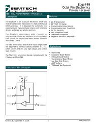
RClamp0524J - Semtech
RClamp0524J - Semtech
RClamp0524J - Semtech

Create successful ePaper yourself
Turn your PDF publications into a flip-book with our unique Google optimized e-Paper software.
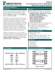
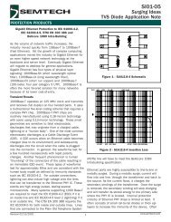
PROTECTION PRODUCTS - RailClamp ®<br />
Description<br />
RailClamps ® are ultra low capacitance TVS arrays<br />
designed to protect high speed data interfaces. This<br />
series has been specifically designed to protect sensitive<br />
components which are connected to high-speed data<br />
and transmission lines from overvoltage caused by ESD<br />
(electrostatic discharge), CDE (Cable Discharge Events),<br />
and EFT (electrical fast transients).<br />
The RClamp TM 0524J has a typical capacitance of only<br />
0.30pF between I/O pins. This allows it to be used on<br />
circuits operating in excess of 3GHz without signal<br />
attenuation. They may be used to meet the ESD<br />
immunity requirements of IEC 61000-4-2,<br />
Level 4 (±15kV air, ±8kV contact discharge). Each<br />
device is designed to protect four lines (two differential<br />
pairs).<br />
The <strong>RClamp0524J</strong> is in a 8-pin, RoHS/WEEE compliant,<br />
SLP2710P8 package. It measures 2.7 x 1.0 x 0.5mm.<br />
The leads are spaced at a pitch of 0.5mm and are finished<br />
with lead-free NiPdAu. They are designed for easy<br />
PCB layout by allowing the traces to run straight through<br />
the device. The combination of small size, low capacitance,<br />
and high level of ESD protection makes them a<br />
flexible solution for applications such as HDMI,<br />
DisplayPort TM , MDDI, and eSATA interfaces.<br />
Dimensions<br />
<strong>RClamp0524J</strong><br />
RailClamp ®<br />
Ultra Low Capacitance TVS Arrays<br />
PRELIMINARY<br />
Features<br />
ESD protection for high-speed data lines to<br />
IEC 61000-4-2 (ESD) ±15kV (air), ±8kV (contact)<br />
IEC 61000-4-5 (Lightning) 5A (8/20μs)<br />
IEC 61000-4-4 (EFT) 40A (5/50ns)<br />
Package design optimized for high speed lines<br />
Flow-Through design<br />
Protects four I/O lines<br />
Low capacitance: 0.3pF typical (I/O to I/O)<br />
Low clamping voltage<br />
Low operating voltage: 5V<br />
Solid-state silicon-avalanche technology<br />
Mechanical Characteristics<br />
SLP2710P8 8-pin package (2.7 x 1.0 x 0.5mm)<br />
RoHS/WEEE Compliant<br />
Lead Pitch: 0.5mm<br />
Lead finish: NiPdAu<br />
Marking: Marking Code<br />
Packaging: Tape and Reel per EIA 481<br />
Applications<br />
High Definition Multi-Media Interface (HDMI)<br />
Digital Visual Interface (DVI)<br />
DisplayPort TM Interface<br />
MDDI Ports<br />
LVDS<br />
Serial ATA<br />
PCI Express<br />
Circuit Diagram<br />
1 2<br />
2.70<br />
0.40<br />
1.00<br />
0.50<br />
0.60<br />
0.20<br />
Pin 1 Pin 2 Pin 3 Pin 4<br />
0.50<br />
GND<br />
Revision 07/20/2010<br />
Nominal Dimensions in mm<br />
4-Line Protection<br />
1 www.semtech.com
<strong>RClamp0524J</strong><br />
PROTECTION PRODUCTS<br />
Absolute Maximum Rating<br />
PRELIMINARY<br />
Rating<br />
Symbol<br />
Value<br />
Units<br />
Peak<br />
Peak<br />
Pulse Power (tp = 8/20μs)<br />
Pulse Current (tp = 8/20μs)<br />
ESD per IEC 61000-4-2 (Air)<br />
ESD per IEC 61000-4-2 (Contact)<br />
P pk<br />
50<br />
1 Watts<br />
I PP<br />
5 A<br />
V ESD<br />
+/- 17<br />
+/- 12<br />
kV<br />
Operating<br />
Temperature<br />
T J<br />
-55<br />
to +125<br />
° C<br />
Storage<br />
Temperature<br />
T STG<br />
55 to +150<br />
- ° C<br />
Electrical Characteristics (T=25 o C)<br />
Parameter<br />
Symbol<br />
Conditions<br />
Minimum<br />
Typical<br />
Maximum<br />
Units<br />
Reverse<br />
Stand-Off Voltage V RWM<br />
Any<br />
I/O pin to ground<br />
5 V<br />
Reverse<br />
Breakdown Voltage<br />
V R<br />
B<br />
I t<br />
= 1mA<br />
Any I/O pin to ground<br />
6 V<br />
Reverse<br />
Leakage Current I R<br />
V RWM<br />
= 5V, T=25° C<br />
Any I/O pin to ground<br />
Clamping<br />
Voltage<br />
V C<br />
I PP<br />
= 1A, tp = 8/20μs<br />
Any I/O pin to ground<br />
Junction<br />
Capacitance<br />
C j<br />
V R<br />
= 0V, f = 1MHz<br />
Between I/O pins<br />
Junction<br />
Capacitance<br />
C j<br />
V R<br />
= 0V, f = 1MHz<br />
Any I/O pin to ground<br />
1 μA<br />
15<br />
V<br />
0.30<br />
0.<br />
4 pF<br />
0.8<br />
pF<br />
© 2011 <strong>Semtech</strong> Corp. 2<br />
www.semtech.com
<strong>RClamp0524J</strong><br />
PROTECTION PRODUCTS<br />
Typical Characteristics<br />
Non-Repetitive Peak Pulse Power vs. Pulse Time<br />
Power Derating Curve<br />
PRELIMINARY<br />
Peak Pulse Power - P PP (kW)<br />
10<br />
1<br />
0.1<br />
0.01<br />
0.1 1 10 100 1000<br />
Pulse Duration - tp (us)<br />
% of Rated Power or IPP<br />
110<br />
100<br />
90<br />
80<br />
70<br />
60<br />
50<br />
40<br />
30<br />
20<br />
10<br />
0<br />
0 25 50 75 100 125 150<br />
Ambient Temperature - T A ( o C)<br />
Pulse Waveform<br />
Clamping Voltage vs. Peak Pulse Current<br />
Percent of I PP<br />
110<br />
100<br />
90<br />
80<br />
70<br />
60<br />
50<br />
40<br />
30<br />
20<br />
10<br />
e -t td = I PP /2<br />
Waveform<br />
Parameters:<br />
tr = 8µs<br />
td = 20µs<br />
Clamping Voltage -V C (V)<br />
40<br />
35<br />
30<br />
25<br />
20<br />
15<br />
10<br />
5<br />
Line to Line<br />
Line to Gnd<br />
Waveform<br />
Parameters:<br />
tr = 8µs<br />
td = 20µs<br />
0<br />
0 5 10 15 20 25 30<br />
Time (µs)<br />
0<br />
0 1 2 3 4 5 6<br />
Peak Pulse Current - I PP (A)<br />
Normalized Capacitance vs. Reverse Voltage<br />
ESD Clamping for +8kV pulse per IEC 61000-4-2<br />
C J (V R ) / C J (V R =0)<br />
1.5<br />
1.4<br />
1.3<br />
1.2<br />
1.1<br />
1<br />
0.9<br />
0.8<br />
0.7<br />
0.6<br />
0.5<br />
0.4<br />
0.3<br />
0.2<br />
0.1<br />
0<br />
f = 1 MHz<br />
0 1 2 3 4 5<br />
Reverse Voltage - V R (V)<br />
© 2011 <strong>Semtech</strong> Corp. 3<br />
www.semtech.com
<strong>RClamp0524J</strong><br />
PROTECTION PRODUCTS<br />
Typical Characteristics (Con’t)<br />
Insertion Loss S21 - I/O to I/O<br />
Insertion Loss S21 - I/O to GND<br />
PRELIMINARY<br />
CH1 S21 LOG 6 dB / REF 0 dB<br />
CH1 S21 LOG 6 dB / REF 0 dB<br />
1: -0.076 dB<br />
900 MHz<br />
1: -0.086 dB<br />
900 MHz<br />
0 dB<br />
1 2<br />
3<br />
2: -0.062 dB<br />
1.8 GHz<br />
0 dB<br />
1 2<br />
3<br />
2: -0.0336 dB<br />
1.8 GHz<br />
-6 dB<br />
3: -0.1087 dB<br />
2.5 GHz<br />
-6 dB<br />
3: -0.126 dB<br />
2.5 GHz<br />
-12 dB<br />
-12 dB<br />
-18 dB<br />
-18 dB<br />
-24 dB<br />
-24 dB<br />
-30 dB<br />
-30 dB<br />
-36 dB<br />
-36 dB<br />
-42 dB<br />
-42 dB<br />
-48 dB<br />
1<br />
MHz<br />
10<br />
MHz<br />
100<br />
MHz<br />
1<br />
GHz<br />
3<br />
GHz<br />
-48 dB<br />
1<br />
MHz<br />
10<br />
MHz<br />
100<br />
MHz<br />
1<br />
GHz<br />
3<br />
GHz<br />
START . 030 MHz STOP 3000<br />
. 000 000 MHz<br />
START . 030 MHz STOP 3000<br />
. 000 000 MHz<br />
© 2011 <strong>Semtech</strong> Corp. 4<br />
www.semtech.com
<strong>RClamp0524J</strong><br />
PROTECTION PRODUCTS<br />
Applications Information<br />
Design Recommendations for HDMI Protection<br />
Adding external ESD protection to HDMI ports can be<br />
challenging. First ESD protection devices have an<br />
inherent junction capacitance. However, adding even a<br />
small amount of capacitance will cause the impedance<br />
of the differential pair to drop. Second, large packages<br />
and land pattern requirements cause discontinuities<br />
that adversely affect signal integrity. The<br />
<strong>RClamp0524J</strong> is specifically designed for protection of<br />
high-speed interfaces such as HDMI. They present<br />
±8kV ESD contact discharges<br />
(>±15kV air discharge) as outlined in IEC 61000-4-2.<br />
Each device is in a leadless SLP package that is less<br />
than 1.1mm wide. They are designed such that the<br />
traces flow straight through the device. The narrow<br />
package and flow-through design reduces<br />
discontinuities and minimizes impact on signal integrity.<br />
This becomes even more critical as signal speeds<br />
increase.<br />
Pin Configuration<br />
Figure 1 is an example of how to route the high speed<br />
differential traces through the <strong>RClamp0524J</strong>. The<br />
solid line represents the PCB trace. The PCB traces<br />
are used to connect the pin pairs for each line (pin 1 to<br />
pin 8, pin 2 to pin 7, pin 3 to pin 6, pin 4 to pin 5). For<br />
example, line 1 enters at pin 1 and exits at Pin 8 and<br />
the PCB trace connects pin 1 and 8 together. This is<br />
true for lines connected at pins 2, 3, and 4 also.<br />
Ground is connected at the center tabs. One large<br />
ground pad should be used in lieu of two separate<br />
pads.<br />
TDR Measurements for HDMI<br />
The combination of low capacitance, small package, and<br />
flow-through design means it is possible to use these<br />
devices to meet the HDMI impedance requirements of<br />
100 Ohm ±15% without any PCB board modification.<br />
Figures 3 and 4 show impedance test results for a TDR<br />
risetime of 200ps and 100ps respectively, using a<br />
<strong>Semtech</strong> evaluation board with 100 Ohm traces throughout.<br />
Measurements were taken using a TDR method as<br />
outlined in the HDMI Compliance Test Specification<br />
(CTS). In each case, the device meets the HDMI CTS<br />
HDMI Connector<br />
8 7 GND 6 5<br />
1 2 GND 3 4<br />
Pin<br />
12<br />
11<br />
10<br />
9<br />
8<br />
7<br />
6<br />
5<br />
4<br />
3<br />
2<br />
1<br />
1<br />
GND<br />
1<br />
GND<br />
Identification<br />
1,<br />
2, 3, 4<br />
Input Lines<br />
5, 6, 7, 8<br />
GND<br />
GND<br />
GND<br />
PRELIMINARY<br />
Output Lines<br />
(No Internal Connection)<br />
Ground<br />
SLP2710P8 Pin Configuration (Top View)<br />
Figure 1. Flow through Layout Using<br />
RClam<br />
Clamp052<br />
p0524J<br />
© 2011 <strong>Semtech</strong> Corp. 5<br />
www.semtech.com
<strong>RClamp0524J</strong><br />
PROTECTION PRODUCTS<br />
Applications Information<br />
requirement of 100 Ohm ±15% with plenty of margin.<br />
For signal integrity purposes, the best results will be<br />
obtained by using the <strong>RClamp0524J</strong> to protect the<br />
high-speed differential pairs. This is because the<br />
device is designed such that the data lines from the<br />
connector line up with the I/O pins of the device<br />
without altering the trace routing. Either the<br />
RClamp0504P or <strong>RClamp0524J</strong> may be used to<br />
protect the remaining lines (I 2 C, CEC, and hot plug)<br />
depending on layout constraints.<br />
B<br />
A<br />
PRELIMINARY<br />
Layout Guidelines for Optimum ESD Protection<br />
Good circuit board layout is critical not only for signal<br />
integrity, but also for effective suppression of ESD induced<br />
transients. For optimum ESD protection, the<br />
following guidelines are recommended:<br />
• Place the device as close to the connector as possible.<br />
This practice restricts ESD coupling into<br />
adjacent traces and reduces parasitic inductance.<br />
• The ESD transient return path to ground should be<br />
kept as short as possible. Whenever possible, use<br />
multiple micro vias connected directly from the device<br />
ground pad to the ground plane.<br />
• Avoid running critical signals near board edges.<br />
A B<br />
X-axis 1.905 2.081 (nsec)<br />
Y-axis 101.0 107.0 (Ohm)<br />
Figure 2 - TDR Measurement with 200ps risetime<br />
using <strong>Semtech</strong> Evaluation Board<br />
B<br />
A<br />
A B<br />
X-axis 1.80 2.076 (nsec)<br />
Y-axis 96 108.0 (Ohm)<br />
Figure 3 - TDR Measurement with 100ps risetime<br />
using <strong>Semtech</strong> Evaluation Board<br />
Note: Measurements were taken on SLP HDMI EVAL Rev C Board that has 100Ω<br />
differential traces impedance throughout (No trace Compensation).<br />
© 2011 <strong>Semtech</strong> Corp. 6<br />
www.semtech.com
<strong>RClamp0524J</strong><br />
PROTECTION PRODUCTS<br />
Applications Information<br />
PRELIMINARY<br />
Data 2+<br />
Data 2-<br />
Data 1+<br />
Data 1-<br />
Data 0+<br />
Data 0-<br />
Clk+<br />
Clk-<br />
CEC<br />
SCL<br />
SDA<br />
Gnd<br />
5VPower<br />
HP Detect<br />
<strong>RClamp0524J</strong><br />
<strong>RClamp0524J</strong><br />
To HDMI<br />
Graphics Chip<br />
1 6<br />
RClamp0504P<br />
Figure 4. HDMI Protection Example<br />
Host Tx +<br />
Host Tx -<br />
A +<br />
A -<br />
ESATA<br />
Host Plug<br />
Host Rx -<br />
Host Rx +<br />
1<br />
<strong>RClamp0524J</strong><br />
B -<br />
B +<br />
A +<br />
1<br />
ESATA Device<br />
Plug<br />
A -<br />
B -<br />
B +<br />
-<br />
<strong>RClamp0524J</strong><br />
Figure 5. eSATA A Protection Example<br />
© 2011 <strong>Semtech</strong> Corp. 7<br />
www.semtech.com
<strong>RClamp0524J</strong><br />
PROTECTION PRODUCTS<br />
Applications Information<br />
PRELIMINARY<br />
1<br />
<strong>RClamp0524J</strong><br />
DISPLAY PORT<br />
CONNECTOR<br />
1<br />
<strong>RClamp0524J</strong><br />
Ohm<br />
μ<br />
1<br />
<strong>RClamp0524J</strong><br />
Figure 6. DisplayP<br />
yPor<br />
ort t Protection Example<br />
© 2011 <strong>Semtech</strong> Corp. 8<br />
www.semtech.com
<strong>RClamp0524J</strong><br />
PROTECTION PRODUCTS<br />
Applications Information Spice Model<br />
PRELIMINARY<br />
<strong>RClamp0524J</strong> Spice Model<br />
<strong>RClamp0524J</strong> Spice Parameters<br />
Parameter<br />
IS<br />
BV<br />
VJ<br />
RS<br />
IBV<br />
CJO<br />
TT<br />
U nit<br />
D 1 (LCRD)<br />
D 2 (LCRD)<br />
D3 (TVS)<br />
Amp<br />
1E-20<br />
1E-20<br />
2E-12<br />
Volt<br />
100<br />
100<br />
9.36<br />
Volt<br />
0.<br />
7 0.<br />
7<br />
0. 6<br />
Ohm<br />
0.458<br />
1.<br />
0<br />
2. 6<br />
Farad<br />
0.4E-12<br />
0.6E-12<br />
56E-12<br />
Amp<br />
1E-3<br />
1E-3<br />
1E-3<br />
sec<br />
2.541E-<br />
9 2.541E-<br />
9 2.541E- 9<br />
M --<br />
0.01<br />
0.01<br />
0.23<br />
N --<br />
1.<br />
1 1.<br />
1<br />
1. 1<br />
EG<br />
eV<br />
1.11<br />
1.11<br />
1.11<br />
© 2011 <strong>Semtech</strong> Corp. 9<br />
www.semtech.com
<strong>RClamp0524J</strong><br />
PROTECTION PRODUCTS<br />
Outline Drawing - SO-8 SLP2710P8<br />
PRELIMINARY<br />
A<br />
PIN 1<br />
INDICATOR<br />
(LASER MARK)<br />
aaa C<br />
A2<br />
D<br />
A1<br />
B<br />
E<br />
A<br />
C<br />
SEATING<br />
PLANE<br />
DIMENSIONS<br />
MILLIMETERS<br />
DIM<br />
MIN NOM MAX<br />
A<br />
A1<br />
A2<br />
0.47<br />
0.00<br />
0.50<br />
0.03<br />
(0.13)<br />
0.53<br />
0.05<br />
b 0.15 0.20 0.25<br />
b1 0.35 0.40 0.45<br />
D 2.60 2.70 2.80<br />
E 0.90 1.00 1.10<br />
e 0.50 BSC<br />
e1 0.60 BSC<br />
L<br />
N<br />
0.30 0.38<br />
8<br />
0.43<br />
aaa<br />
bbb<br />
0.08<br />
0.10<br />
R0.125<br />
b1xN<br />
bbb<br />
C A B<br />
1<br />
2<br />
E/2<br />
LxN<br />
N<br />
e<br />
e1<br />
2X R0.075<br />
7 PLACES<br />
bxN<br />
bbb C A B<br />
D/2<br />
NOTES:<br />
1. CONTROLLING DIMENSIONS ARE IN MILLIMETERS (ANGLES IN DEGREES).<br />
Land Pattern - SLP2710P8<br />
P1<br />
Z<br />
(C)<br />
X<br />
G<br />
P<br />
X1<br />
Y<br />
(Y1)<br />
DIMENSIONS<br />
DIM INCHES MILLIMETERS<br />
C (.034)<br />
(0.875)<br />
G .008<br />
0.20<br />
P .020<br />
0.50<br />
P1 .024 0.60<br />
X .008<br />
0.20<br />
X1 .016 0.40<br />
Y .027<br />
0.675<br />
Y1 (.061) (1.55)<br />
Z .061<br />
1.55<br />
NOTES:<br />
1. CONTROLLING DIMENSIONS ARE IN MILLIMETERS (ANGLES IN DEGREES).<br />
2. THIS LAND PATTERN IS FOR REFERENCE PURPOSES ONLY.<br />
CONSULT YOUR MANUFACTURING GROUP TO ENSURE YOUR<br />
COMPANY'S MANUFACTURING GUIDELINES ARE MET.<br />
© 2011 <strong>Semtech</strong> Corp. 10<br />
www.semtech.com
<strong>RClamp0524J</strong><br />
PROTECTION PRODUCTS<br />
Marking Codes<br />
Ordering Information<br />
PRELIMINARY<br />
PIN 1<br />
INDICATOR<br />
YYWW = Date Code<br />
0524J<br />
YYWW<br />
Part Number<br />
Number<br />
of Lines<br />
Note: Lead finish is lead-free NiPdAu.<br />
Qty per<br />
Reel<br />
Reel<br />
Size<br />
<strong>RClamp0524J</strong>.TCT<br />
4 3000<br />
7 Inch<br />
Tape and Reel Specification<br />
Pin 1 Location<br />
User Direction of feed<br />
Device Orientation in Tape<br />
Part<br />
Number A0<br />
B0<br />
K0<br />
<strong>RClamp0524J</strong><br />
1.21 +/-0.10 mm<br />
2.91 +/-0.10 mm<br />
0.66 +/-0.10 mm<br />
Tape<br />
Width<br />
B,<br />
(Max) D D1<br />
E F<br />
K<br />
(MAX)<br />
P P0<br />
P 2 T(MAX)<br />
W<br />
8 mm 4.2 mm<br />
1.5 + 0.1 mm<br />
- 0.0 mm )<br />
0.5 mm<br />
±0.05<br />
1.750±.10<br />
mm<br />
3.5±0.05<br />
mm<br />
2.4 mm<br />
4.0±0.1<br />
mm<br />
4.0±0.1<br />
mm<br />
2.0±0.05<br />
mm<br />
0.4 mm<br />
8.0 mm<br />
+ 0.3 mm<br />
- 0.1 mm<br />
Contact Information<br />
<strong>Semtech</strong> Corporation<br />
Protection Products Division<br />
200 Flynn Road, Camarillo, CA 93012<br />
Phone: (805)498-2111 FAX (805)498-3804<br />
© 2011 <strong>Semtech</strong> Corp. 11<br />
www.semtech.com