PortDG0411 - Semtech
PortDG0411 - Semtech
PortDG0411 - Semtech

You also want an ePaper? Increase the reach of your titles
YUMPU automatically turns print PDFs into web optimized ePapers that Google loves.
Applications<br />
Portable Device Interfaces Protection<br />
TVS Diode Selection<br />
Selection of a suitable component will depend on the number of<br />
lines to be protected, the available board space, and the electrical<br />
characteristics of the circuit to be protected. TVS diodes are<br />
available in a variety of packages and configurations suitable for<br />
use in today’s advanced electronic systems.<br />
No matter what the applications is, however, certain device<br />
parameters and guidelines form the basis for device selection.<br />
TVS Diode Terminology<br />
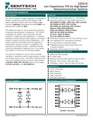
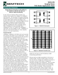
• A typical IV characteristic curve for a bidirectional TVS diode is<br />
shown in Figure 1. The key device parameters<br />
• Reverse Standoff Voltage (V RWM<br />
): This is the normal DC<br />
operating voltage of the device. At this point, the device will<br />
appear as a high impedance to the protected circuit. Discrete<br />
devices are available with standoff voltages ranging from 2.5V<br />
to 70V. This parameter is also referred to as working voltage.<br />
• Reverse Breakdown Voltage (V BR<br />
): This is the point where the<br />
device begins to conduct in avalanche mode and becomes a<br />
low impedance path for the transient. Breakdown voltage is<br />
measured at a test current (I T<br />
), typically 1mA or 10mA.<br />
• Peak Pulse Current (I PP<br />
): Maximum permissible surge current<br />
which the device can withstand without damage. TVS diode<br />
data sheets specify a peak pulse capability for a particular<br />
transient waveform. Most TVS diodes are rated using a<br />
8/20µs or 10/1000µs impulse waveform.<br />
• TVS diodes can withstand higher peak pulse current for<br />
shorter duration pulses.<br />
• Clamping Voltage (V C<br />
): Maximum voltage drop across the TVS<br />
for a particular peak pulse current.<br />
Selection Guidelines<br />
TVS diode selection involves comparison of device parameters<br />
with circuit conditions. The following selection guidelines are<br />
recommended:<br />
• Select a device with a reverse standoff voltage greater than or<br />
equal to the normal operating voltage of the circuit.<br />
• Select a device which is capable of dissipating the expected<br />
transcient peak pulse current.<br />
• The device clamping voltage should be less than the maximum<br />
voltage handling capability of the protected circuit for the<br />
same pulse waveforms.<br />
• For systems using high speed data rates, device junction<br />
capacitance will have to be considered. <strong>Semtech</strong><br />
manufactures special low capacitance devices for those<br />
applications.<br />
There may be applications where the actual transient current<br />
cannot be defined. Often, the designer will have to meet the<br />
requirements of certain transient immunity specifications. At the<br />
very least, identification of the source of the threat is necessary;<br />
lightning, inductive switching, ESD, etc.<br />
Device<br />
Parameter<br />
Circuit Conditions<br />
V RWM ≥ Normal circuit operating voltage<br />
I PP ≥ Expected transient current<br />
V C<br />
≤<br />
Maximum allowable voltage across the<br />
protected component<br />
C J <<br />
Maximum loading capacitance for<br />
signal integrity<br />
Figure 2 - Selection Summary<br />
Figure 1 - Bidirectional IV Characteristic Curve<br />
Protection Design Guide ©2011 Copyright <strong>Semtech</strong> Corporation. All rights reserved. All Clamp products are registered trademarks of <strong>Semtech</strong> Corporation. 33