RIGHT-click here - Monitoring Times
RIGHT-click here - Monitoring Times
RIGHT-click here - Monitoring Times

You also want an ePaper? Increase the reach of your titles
YUMPU automatically turns print PDFs into web optimized ePapers that Google loves.
RADIO RESTORATIONS<br />
BRINGING OLD RADIOS BACK TO LIFE<br />
More on the Midget Arvin and<br />
Sets You Don’t Want to Plug In!<br />
Marc Ellis, N9EWJ<br />
marcellis@monitoringtimes.com<br />
In last month’s column, I mentioned how<br />
my wish for a project radio small enough<br />
to fit on my currently cluttered benchtop<br />
seemed to have been almost providentially<br />
granted. While attending the Antique Wireless<br />
Asociation spring meet, which is always held<br />
in conjunction with the AWA May board meeting,<br />
I came across the perfect set: one of those<br />
midget metal-cased Arvins. However, the very<br />
diminutiveness that seemed to be such an asset<br />
had the effect of stopping me in my tracks a little<br />
earlier in this work session than I had anticipated.<br />
But I’m getting ahead of my story.<br />
I began this month’s work session with the<br />
prospect of spending a few quiet hours recapping<br />
the little Arvin. As regular readers know,<br />
I start most radio restorations with replacement<br />
of all paper and electrolytic capacitors. Turning<br />
the set upside down, I took a good look at its<br />
underside for the first time. What I saw caused<br />
me to quickly abandon my plans for a wholesale<br />
recapping.<br />
The wiring is so tight in this little chassis<br />
that it must have been installed in layers.<br />
I thought I might do more harm than good as<br />
I disturbed various connections to wire in the<br />
new capacitors. It would be easy to create short<br />
circuits as I moved parts around. So I decided to<br />
use a servicing technique that would have been<br />
normal for the era when the set was current: turn<br />
it on, look for trouble, and correct any faults that<br />
occur as they come up.<br />
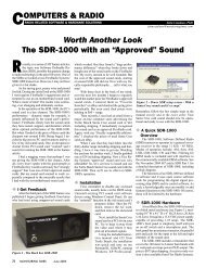
Rivets on the unusual cord restraint had to be<br />
drilled out so it could be removed (see text).<br />
❖ Needed: A Line Cord<br />
But before I could power up this radio, I<br />
would have to provide it with a line cord. The<br />
original was clipped off w<strong>here</strong> it entered the<br />
chassis. Looking at the deteriorating remnants<br />
of the cord left inside the chassis, I could see<br />
why. Like most rubber zip cord of the time, this<br />
one must have become a safety hazard with the<br />
usual flaking insulation and exposed wire.<br />
62 MONITORING TIMES August 2012<br />
Making way for the new line cord turned<br />
out to be a bit of a project. The remnants of the<br />
old cord were held in a tight grip by a restraint<br />
system I had never seen before. The cord was<br />
sandwiched between a couple of small pieces<br />
of insulating board that were riveted to each<br />
other and the chassis apron. The rivets had to be<br />
drilled out so that the restraint system could be<br />
removed. Having done that, I replaced it with a<br />
rubber grommet, ran the new cord through, and<br />
prevented it from pulling out with a knot on the<br />
inside of the chassis.<br />
❖ Checking the Tubes<br />
Once the new cord was hooked up, I removed<br />
the radio’s four tubes and checked them<br />
against the chassis layout shown in Rider’s<br />
to make sure that the correct tube had been<br />
installed in each socket. All the tubes checked<br />
out fine on my Navy TV-7, though I wouldn’t<br />
have been surprised to find one with an open<br />
heater – which is one of the most common faults<br />
in an a.c.-d.c. receiver.<br />
With the tubes out of their sockets, I cleared<br />
out most of the dust from the chassis and various<br />
crevices using nothing more than a damp cloth.<br />
Though t<strong>here</strong> was plenty of dust, t<strong>here</strong> was little<br />
or no pitting – a sign that this radio had been<br />
stored inside, not in a garage or shed w<strong>here</strong> t<strong>here</strong><br />
was no environmental control. Before each tube<br />
was permanently seated in its socket, I sprayed<br />
its pins with contact cleaner and ran it in and out<br />
of the socket a few times.<br />
❖ The Smoke Test<br />
Now I was ready to try the radio – an<br />
operation that seemed very strange to me with<br />
the original capacitors still in place. I plugged<br />
it in through a little autotransformer I have that<br />
has four voltage steps – at about 40, 60, 80 and<br />
120 volts. The autotransformer was powered,<br />
in turn, through an isolation transformer. The<br />
latter wasn’t technically necessary, since this<br />
radio has a “floating ground” (see last month’s<br />
column). That should protect the user from a<br />
hot chassis situation, but its protection could be<br />
compromised by a leaky bypass capacitor.<br />
Before turning up the voltage, I set up a<br />
multimeter to monitor the power supply’s d.c.<br />
output by connecting it from the 35Z5 cathode<br />
to the floating ground. A lack of d.c. voltage or<br />
a sudden voltage falloff would be an indication<br />
of a possible short and a signal to turn off the<br />
radio immediately.<br />
Turning the set on, I increased the autotransformer<br />
voltage slowly, leaving it set at each<br />
switch position for several minutes. T<strong>here</strong> was<br />
no smoke, but as I reached the 80-volt position<br />
I began to notice a loud, raspy a.c. hum that was<br />
unaffected by the position of the volume control.<br />
This is the classic indication of one or more open<br />
filter capacitors.<br />
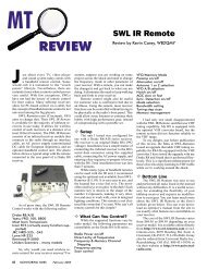
❖ The Capacitor Problem<br />
The Arvin is equipped with a three-section<br />
electrolytic capacitor. Two of these (40 uf and 20<br />
uf at 150 volts) are filter capacitors and the third<br />
(20 uf at 25 volt) is the cathode bypass for the<br />
50L6 power amplifier. My next move would be<br />
to change out this capacitor, but <strong>here</strong>’s w<strong>here</strong> I<br />
ran into trouble. None of the multi-section caps<br />
in my stock could possibly fit in the tiny space<br />
available. And even the most compact unit available<br />
new was an inch too long.<br />
The Arvin’s cramped chassis makes capacitor<br />
replacement an adventure.<br />
It looks as if the only course open to me<br />
is to order three individual caps of the correct<br />
sizes and somehow shoehorn them into the small<br />
space available. Modern low-voltage electrolytics<br />
tend to be quite small, so I’m hoping I<br />
can make this scheme work out. Next month’s<br />
column should tell the tale.<br />
❖ Don’t Plug These Sets In!<br />
This topic was inspired by a query that<br />
recently came across the desk of our publisher,<br />
Bob Grove. I knew some of the answer and, in<br />
researching the rest, I came across some very<br />
interesting material.<br />
Here’s the issue: almost every serious radio<br />
collector will eventually come across a routinelooking<br />
radio, usually a table model in a wood<br />
cabinet, that is designed to run on some value<br />
of d.c. – generally 110 volts, 6 volts or 32 volts.<br />
Quite often, the radio will be internally fried<br />
because somebody in the past has mistaken it<br />
for a routine a.c. model and plugged it into the<br />
a.c. line.