You also want an ePaper? Increase the reach of your titles
YUMPU automatically turns print PDFs into web optimized ePapers that Google loves.
Pulse and Digital Circuits Venkata Rao K., Rama Sudha K. and Manmadha Rao G.<br />
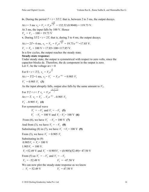
iv. During the period T < t < 3T/2, that is, between 2 <strong>to</strong> 3 ms, the output decays.<br />
1.0<br />
10<br />
At t = 3 ms v<br />
o<br />
=<br />
f<br />
At 3 ms, the input falls by 100 V. Hence<br />
V g<br />
= V – 100 = 19.73 V<br />
f<br />
V = V e<br />
e = 132.32 (0.9048) = 119.73 V.<br />
v. During 3T /2 < t < 2T, that is, d uring 3 <strong>to</strong> 4 ms, the output decays.<br />
1.0<br />
10<br />
0.1<br />
At t = 2T= 4 ms, v<br />
o<br />
= V<br />
h<br />
= V g<br />
e = 19.73 e =17.85 V.<br />
V<br />
j<br />
= V<br />
h<br />
+ 100 V = 17.85+100=117.85 V.<br />
In a few cycles, the output reaches the steady state.<br />
Steady-state response:<br />
Under steady state, the output is symmetrical with respect <strong>to</strong> zero volts, since the<br />
capaci<strong>to</strong>r blocks dc. Therefore, the dc component in the output is zero.<br />
Let V 1 be the voltage at t = 0<br />
t<br />
<br />
For 0 < t < T/2, v<br />
o<br />
= V1<br />
e<br />
'<br />
0.1<br />
At t = T/2=1 ms, vo<br />
= V1<br />
= V<br />
1e<br />
= 0.905 V<br />
1<br />
'<br />
V<br />
1<br />
= 0.905 V<br />
1<br />
(3)<br />
As the input abruptly falls, output also falls by the same amount <strong>to</strong> V 2 .<br />
(tT / 2)<br />
<br />
For T/2 < t < T v<br />
o<br />
= V<br />
2<br />
e<br />
'<br />
0.1<br />
At t = T, v o<br />
= V 2 = V 2<br />
e = 0.905 V 2<br />
'<br />
V2 = 0.905 V<br />
2<br />
(4)<br />
For symmetrical wave<br />
' '<br />
V<br />
1<br />
= V 2<br />
and V<br />
1<br />
= V2<br />
(5)<br />
'<br />
'<br />
V<br />
1<br />
V2<br />
= 100 V and V1<br />
V 2<br />
= 100 V (6)<br />
'<br />
From (6), we have V1 V2<br />
= 100 V (7)<br />
And from (3), we have V1<br />
= V2<br />
(8)<br />
'<br />
Substituting (8) in (7), we have V<br />
1<br />
+ V 1<br />
= 100 V (9)<br />
'<br />
From (3), we have V<br />
1<br />
= 0.905 V<br />
1<br />
Substituting in (9)<br />
0.905V 1<br />
+ V<br />
1= 100 V<br />
1.905V 1<br />
= 100 V.<br />
'<br />
V<br />
1<br />
=52.49 V and V 1<br />
= 0.905V 1<br />
= (0.905)(52.49)= 47.50 V<br />
' '<br />
From (5) as V<br />
1<br />
= V2<br />
an d V1<br />
= V2<br />
'<br />
V 2<br />
= –52.49 V V 2<br />
= –47.50 V<br />
We can now plot the steady-state response as we know<br />
'<br />
V = 52.49 V<br />
V = 47.50 V<br />
1 1<br />
© 2010 Dorling Kindersley India Pvt. Ltd 16


![[Productnaam] Marketingplan - Pearson](https://img.yumpu.com/26285712/1/190x132/productnaam-marketingplan-pearson.jpg?quality=85)


