


Create successful ePaper yourself
Turn your PDF publications into a flip-book with our unique Google optimized e-Paper software.
<strong>Quick</strong>-<strong>Start</strong> <strong>Guide</strong><br />
Wall Dimmer – 1000W<br />
Model: 4711<br />
Tools Needed<br />
• Phillips and Standard screwdrivers<br />
• Wire cutter / stripper<br />
• Voltage tester to identify wires inside the junction box<br />
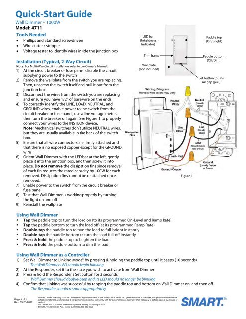
LED bar<br />
(brightness<br />
Indicator)<br />
Paddle top<br />
(On/Bright)<br />
Installation (Typical, 2-Way Circuit)<br />
Note: For Multi-Way Circuit installation, refer to the Owner’s Manual.<br />
1) At the circuit breaker or fuse panel, disable the circuit<br />
supplying power to the switch<br />
2) Remove the wallplate from the switch you are replacing.<br />
Then, unscrew the switch itself and pull it out from the<br />
junction box<br />
3) Disconnect the wires from the switch you are replacing<br />
and ensure you have 1/2” of bare wire on the ends<br />
4) To correctly identify the LINE, LOAD, NEUTRAL, and<br />
GROUND wires, enable power to the switch from the<br />
circuit breaker or fuse panel, use a line voltage meter,<br />
then turn the breaker off again. See Figure 1 to properly<br />
connect your wires to the INSTEON device.<br />
Note: Mechanical switches don’t utilize NEUTRAL wires,<br />
but they are usually available in the back of the switch<br />
box.<br />
5) Ensure that all wire connectors are firmly attached and<br />
that there is no exposed copper except for the GROUND<br />
wire<br />
6) Orient Wall Dimmer with the LED bar at the left, gently<br />
place it into the junction box, and then screw it into<br />
place. Do not remove the dissipation fins since removal<br />
of each fin reduces the rated capacity by 100W for each<br />
removed. Dissipation fins cannot be reattached once<br />
removed.<br />
7) Enable power to the switch from the circuit breaker or<br />
fuse panel<br />
8) Test that Wall Dimmer is working properly by turning<br />
the light on and off<br />
9) Reinstall the wallplate<br />
Trim frame<br />
Wallplate<br />
(not included)<br />
Figure 1<br />
Paddle bottom<br />
(Off/Dim)<br />
Set button (push)<br />
Air gap (pull)<br />
Using Wall Dimmer<br />
• Tap the paddle top to turn the load on (to its programmed On-Level and Ramp Rate)<br />
• Tap the paddle bottom to turn the load off (at its programmed Ramp Rate)<br />
• Double-tap the paddle top to turn the load to full-bright instantly<br />
• Double-tap the paddle bottom to turn the load full-off instantly<br />
• Press & hold the paddle top to brighten the load<br />
• Press & hold the paddle bottom to dim the load<br />
Using Wall Dimmer as a Controller<br />
1) Set Wall Dimmer to Linking Mode* by pressing & holding the paddle top until it beeps (10 seconds)<br />
The Wall Dimmer LED should begin blinking<br />
2) At the Responder, set it to the state you wish to activate from Wall Dimmer<br />
3) Press & hold the Responder’s Set button for 3 seconds<br />
Wall Dimmer should double-beep and its LED should no longer be blinking<br />
4) Confirm that Linking was successful by tapping the paddle top and bottom on Wall Dimmer on, and then off<br />
The Responder should respond appropriately<br />
Page 1 of 2<br />
Rev. 09-20-2010<br />
SMART Limited Warranty – SMART warrants to original consumer of this product for a period of 2 years from date of purchase, this product will be free from<br />
defects in material & workmanship & will perform in substantial conformity with its Owner's Manual. Warranty shall not apply to defects caused by misuse or<br />
neglect.<br />
U.S. Patent No. 7,345,998, International patents pending © Copyright 2010<br />
SMART, 16542 Millikan Ave., Irvine, CA 92606, 866-883-9220
<strong>Quick</strong>-<strong>Start</strong> <strong>Guide</strong><br />
Wall Dimmer – 1000W<br />
Using Wall Dimmer as a Responder<br />
1) Set your INSTEON Controller to Linking Mode*. (For most Controllers, press & hold an On or Scene button for 10<br />
seconds or the Set button for 3 seconds.)<br />
2) Press & hold the paddle top on Wall Dimmer until it double-beeps (10 seconds)<br />
The Wall Dimmer Status LED should flash once, and then turn on solid<br />
3) Confirm that Linking was successful by tapping the button you just Linked to on the Controller<br />
Wall Dimmer should respond appropriately<br />
Using Wall Dimmer to Bridge Phases<br />
Wall Dimmer can help bridge the phases in your home, allowing RF-only devices access to power line-only devices. For<br />
the best INSTEON network performance, it is recommended that you install at least two dual-band INSTEON products.<br />
Use the following procedure to test that the phases have been bridged:<br />
1) Install a second dual-band INSTEON device if you don’t already have one installed<br />
2) <strong>Start</strong> Phases Bridging Detection Mode* by tapping the Set button on Wall Dimmer four times quickly<br />
Wall Dimmer should begin beeping and the LED should be solid<br />
3) Check the LED behavior of the other dual-band devices to see if they are on the opposite phase<br />
If at least one of the other dual-band device LEDs is blinking green or is bright solid white or blue, the device is on the<br />
opposite phase. Continue to step 4.<br />
If none of the dual-band devices exhibit the behavior above, they are on the same phase. Try one or both of the<br />
following:<br />
• Follow steps 2 and 3 with the other dual-band devices to see if they are exhibiting the desired LED behavior<br />
• Move a dual-band device to another location until it exhibits the desired LED behavior<br />
4) Tap the Set button on Wall Dimmer to exit Phase Bridging Detection Mode<br />
Wall Dimmer should stop beeping<br />
Complete Instructions, Troubleshooting, and Tech Support<br />
Call: Tech. Support @ 866-883-9220<br />
Contact Us Online: www.smartproline.com<br />
ETL/UL Warning<br />
CAUTION - To reduce the risk of overheating and possible damage to other equipment do not install to control a receptacle, a<br />
motor-operated appliance, a fluorescent lighting fixture, or a transformer-supplied appliance.<br />
Gradateurs commandant une lampe a filament de tungstene – afin de reduire le risque de surchauffe et la possibilite<br />
d’endommagement a d’autres materiels, ne pas installer pour commander une prise, un appareil a moteur, une lampe<br />
flourescente ou un appareil alimente par un transformateur.<br />
*Setup Modes will automatically time out after 4 minutes.<br />
Page 2 of 2<br />
Rev. 09-20-2010<br />
SMART Limited Warranty – SMART warrants to original consumer of this product for a period of 2 years from date of purchase, this product will be free from<br />
defects in material & workmanship & will perform in substantial conformity with its Owner's Manual. Warranty shall not apply to defects caused by misuse or<br />
neglect.<br />
U.S. Patent No. 7,345,998, International patents pending © Copyright 2010<br />
SMART, 16542 Millikan Ave., Irvine, CA 92606, 866-883-9220


