

Installation Instructions - Smarthome
Installation Instructions - Smarthome
Installation Instructions - Smarthome

You also want an ePaper? Increase the reach of your titles
YUMPU automatically turns print PDFs into web optimized ePapers that Google loves.
:5:5%:5%<br />
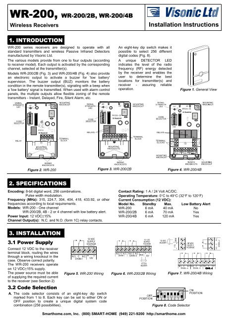
Wireless Receivers<br />
<strong>Installation</strong> <strong>Instructions</strong><br />
,1752'8&7,21<br />
WR-200 series receivers are designed to operate with all<br />
standard transmitters and wireless Passive Infrared Detectors<br />
manufactured by Visonic Ltd.<br />
The various models provide from one to four outputs (according<br />
to receiver model). Each output is activated by the corresponding<br />
channel, selected at the transmitter(s).<br />
Models WR-200/2B (Fig. 3) and WR-200/4B (Fig. 4) also provide<br />
an electronic output to activate a buzzer for 'low battery'<br />
supervision. The buzzer output (BUZ) monitors the battery<br />
condition in the remote transmitter(s), signaling with a beep when<br />
a 'low battery' signal is transmitted. When used with alarm control<br />
panels, the multiple outputs allow flexible zoning of the remote<br />
transmitters - Instant, Delayed, Fire, Silent Alarm, etc.<br />
An eight-key dip switch makes it<br />
possible to select 256 different<br />
digital codes (Fig. 8).<br />
A unique DETECTOR LED<br />
indicates the level of the radio<br />
frequency (RF) energy detected<br />
by the receiver and enables the<br />
user to determine the best<br />
locations for transmitter(s) and<br />
receiver - assuring reliable<br />
operation.<br />
Figure 1. General View<br />
Figure 2. WR-200 Figure 3. WR-200/2B Figure 4. WR-200/4B<br />
63(&,),&$7,216<br />
Encoding: 8-bit digital word, 256 combinations.<br />
Pulse width modulation.<br />
Frequency (MHz): 315, 224.7, 304, 404, 418, 433.92, or other<br />
frequencies according to local requirements.<br />
Models: WR-200 - One channel<br />
WR-200/2B, 4B - 2 or 4 channel with low battery alert.<br />
Power Input: 12 VDC±15%<br />
Channel Output(s): N.C. and N.O. (form 1C) relay contacts.<br />
Contact Rating: 1 A / 24 Volt AC/DC.<br />
Operating Temperature: 0°C to 49°C (32°F to 120°F)<br />
Current Consumption (12 VDC):<br />
Model No. Standby Max. Low Battery Alert<br />
WR-200 6 mA 40 mA No<br />
WR-200/2B 6 mA 70 mA Yes<br />
WR-200/4B 6 mA 120 mA Yes<br />
,167$//$7,21<br />
3RZHU6XSSO\<br />
Connect 12 VDC to the receiver<br />
terminal block, routing the wires<br />
through a wiring knockout in the<br />
case. Observe correct polarity.<br />
The WR-200 receivers operate<br />
on 12 VDC±15% supply.<br />
The power source must be able<br />
of supplying the required current<br />
to the receiver (see Section 2)<br />
&RGH6HOHFWLRQ<br />
A . The code selector consists of an eight-key dip switch<br />
marked from 1 to 8. Each key can be set to either ON or<br />
OFF position to create a unique digital system code<br />
combination (256 possibilities).<br />
Figure 5. WR-200 Wiring Figure 6. WR-200/2B Wiring Figure 7. WR-200/4B Wiring<br />
Figure 8. Code Selector<br />
DE3001 1
B. Select the digital system code by switching the keys either<br />
ON or OFF. This combination must match the code selected<br />
on the companion transmitters. All wireless PIR detectors<br />
transmitters and the receiver in the system must be set to<br />
the same digital code.<br />
CAUTION: The code combination 2, 4, 5, 6, 7, ON / 1, 3, 8<br />
OFF is a factory test code that must not be used. Also<br />
avoid codes such as all keys ON, all keys OFF or<br />
alternating ON-OFF setting . .<br />
'HWHFWRU/('<br />
As previously described, the WR-200 receiver Series has a<br />
special DETECTOR LED which monitors the RF energy<br />
detected by the receiver (Signal Strength indicator). The LED<br />
lights when the RF signal detected by the receiver is above the<br />
minimum reception level. Optimum reception condition is<br />
indicated when the LED lights continuously during<br />
transmission, without flickering.<br />
If the LED does not light continuously during transmission, try to<br />
improve reception by changing the location of the receiver<br />
and/or transmitters.<br />
&KDQQHO2XWSXWV<br />
All channel outputs are provided via c/o relay contacts (type 1C,<br />
NO and NC), with a rating of 1 A/24 Volt DC-AC.<br />
Each relay is activated by a corresponding channel (1, 2, 3 or<br />
4) as set at the transmitters and wireless PIRs.<br />
When activated, the relay remains ON as long as the channel<br />
signal is transmitted.<br />
%X]]HU2XWSXW%8=(Buzzer supplied)<br />
This is a transistor output, activated by the ‘low battery’ signals,<br />
which are automatically transmitted, by Visonic Ltd transmitters<br />
and Wireless PIR Detectors, when battery voltage drops below<br />
7.0 Volts. When a 'low battery' signal is transmitted the buzzer<br />
at the receiver begins sounding short beeps at around 60<br />
second intervals, until the transmitter is identified and the<br />
battery is replaced.<br />
When activated, this output connects power supply (–) at the<br />
'BUZ' terminal. The 'low battery' alert buzzer (12 Volt DC/25 mA<br />
type) should be connected between the 'BUZ' terminal (–) and<br />
the +12 Volt supply terminal (+).<br />
NOTES:<br />
1. The buzzer output may also be activated by turning all four<br />
transmitter channels OFF. However, this selection will not<br />
activate any of the relay outputs, only the buzzer output will<br />
be activated.<br />
2. For some applications, it may be necessary to have a<br />
contact closure in addition to, or instead of the buzzer<br />
operation. In such case, the 'BUZ' output may be used to<br />
activate a reed relay which can be connected in parallel to,<br />
or instead of the buzzer. The reed relay should be a 12 VDC<br />
type, with coil resistance greater than 1000Ω.<br />
3. When two receivers are used in the same location, position<br />
the receivers at least 3 m (10 ft) apart.<br />
4. It is preferred not to install the receiver on or inside a metal<br />
enclosure. In cases where the receiver must be installed<br />
within a metal enclosure, bring the antenna wire out of the<br />
metal enclosure and test the system operation very<br />
carefully.<br />
7HVWLQJ<br />
A. Carefully position the front cover hole over the LED. Secure<br />
the front cover with the screw and screw cover (Fig. 9).<br />
B. Refer to the operating instructions<br />
for the transmitter(s)<br />
being used and<br />
test the receiver with each<br />
transmitter in the system for<br />
range and operation (see<br />
also DETECTOR LED). Figure 9. Cover Assembly<br />
C. Verify operation of the appropriate channel output relay(s) at<br />
the receiver (see CHANNEL OUTPUTS).<br />
D. If you should have a problem with signal reception, change<br />
the location of the transmitter(s) and/or receiver to improve<br />
signal strength (see DETECTOR LED).<br />
0LVFHOODQHRXV1RWHV<br />
Visonic Ltd’s wireless systems are very reliable and are tested<br />
to high standards. However, due to their low transmitting power<br />
and limited range (required by FCC regulations) there are<br />
some limitations to be considered.<br />
A. Receivers may be blocked by radio signals occurring on or<br />
near to their operating frequencies, regardless of the code<br />
selected.<br />
B. A receiver responds to one transmitter signal at a time.<br />
C. Wireless equipment should be tested regularly to determine<br />
if there are sources of interference and to protect against<br />
fault.<br />
Warning: Changes or modifications to this unit not expressly<br />
approved by the party responsible for compliance could void<br />
the user's authority to operate the equipment.


