

TSPOT⢠Flush Mount Analog Temperature Sensor ... - Smarthome
TSPOT⢠Flush Mount Analog Temperature Sensor ... - Smarthome
TSPOT⢠Flush Mount Analog Temperature Sensor ... - Smarthome

Create successful ePaper yourself
Turn your PDF publications into a flip-book with our unique Google optimized e-Paper software.
TSPOT <strong>Flush</strong> <strong>Mount</strong> <strong>Analog</strong> <strong>Temperature</strong> <strong>Sensor</strong><br />
ATS2000A<br />
FEATURES<br />
• High Accuracy<br />
• Wide Measurement Range<br />
• Wide Input Voltage Range<br />
• Multiple <strong>Analog</strong> Outputs<br />
• Outputs Drive Cat 5 Cable<br />
• Screw-Down Wire Connection<br />
• No Hardware or Wall Plate Required<br />
• No Termination Filter Required<br />
APPLICATIONS<br />
• Zoning<br />
• Indoor <strong>Temperature</strong> Measurement<br />
• HVAC Monitoring and Control<br />
• Energy Conservation<br />
• Window Covering Control<br />
DESCRIPTION<br />
The ATS2000A TSPOT (pronounced “tee-spot) is a well-designed<br />
rugged temperature sensor that permits inconspicuous operation<br />
indoors. It snaps easily into a¾” hole in either drywall or wood. Small<br />
size, rugged construction and easy screw-down wire connections<br />
afford easy installation. The unobtrusive styling, high reliability and<br />
exceptional accuracy of the ATS2000A make it a logical choice for<br />
many HVAC control and home automation projects<br />
An installed ATS2000A appears as a low profile, one-inch diameter<br />
disk that is paintable. A labeled four-position, screw-down wire<br />
connector is positioned in back of the sensor body to allow easy<br />
hookup with a compatible home automation controller or data<br />
acquisition system.<br />
Operation of the ATS2000A is extremely simple. Just connect the +V<br />
and COM terminals to a DC power source with a regulated output<br />
voltage between +5Vdc and +30Vdc. Take care to observe the proper<br />
polarity.<br />
Once powered, the ATS2000A produces two linearly scaled analog<br />
signals proportional to temperature when referenced to the COM<br />
terminal. Output signals are voltages between zero and +5V. These<br />
signals may be conveyed over more than 1000’ of cable to the input of<br />
a compatible home automation controller or data acquisition system.<br />
The ATS2000A is designed to drive most types of shielded and<br />
unshielded twisted pair cables such as Category 5.<br />
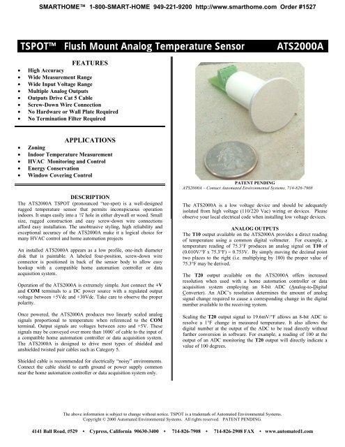
PATENT PENDING<br />
ATS2000A – Contact Automated Environmental Systems, 714-826-7908<br />
The ATS2000A is a low voltage device and should be adequately<br />
isolated from high voltage (110/220 Vac) wiring or devices. Please<br />
observe your local electrical code when installing low voltage devices.<br />
ANALOG OUTPUTS<br />
The T10 output available on the ATS2000A provides a direct reading<br />
of temperature using a common digital voltmeter. For example, a<br />
temperature reading of 75.3°F produces an analog signal on T10 of<br />
(0.010V/°F x 75.3°F) = 0.753V. By simply moving the decimal point<br />
two places to the right (i.e. multiplying by 100) the proper value of<br />
75.3°F may be derived.<br />
The T20 output available on the ATS2000A offers increased<br />
resolution when used with a home automation controller or data<br />
acquisition system employing an 8-bit ADC (<strong>Analog</strong>-to-Digital<br />
Converter). An ADC’s resolution determines the amount of analog<br />
signal change required to cause a corresponding change in the digital<br />
number available to the receiving system.<br />
Scaling the T20 output signal to 19.6mV/°F allows an 8-bit ADC to<br />
resolve a 1°F change in measured temperature. It also allows the<br />
digital number at the output of the ADC to be read directly without<br />
further conversion in software. For example, a reading of 100 at the<br />
output of an ADC monitoring the T20 output will directly indicate a<br />
value of 100 degrees.<br />
Shielded cable is recommended for electrically “noisy” environments.<br />
Connect the cable shield to earth ground or power supply common<br />
near the home automation controller or data acquisition system only.<br />
The above information is subject to change without notice. TSPOT is a trademark of Automated Environmental Systems.<br />
Copyright © 2000 Automated Environmental Systems. All rights reserved. PATENT PENDING.<br />
4141 Ball Road, #529 • Cypress, California 90630-3400 • 714-826-7908 • 714-826-2908 FAX • www.automated1.com
TECHNICAL INFORMATION<br />
ATS2000A CONNECTOR: Four-position screw-down wire connector<br />
POSITION SIGNAL INPUT/ SCALE<br />
DESCRIPTION<br />
NAME OUTPUT FACTOR<br />
1 +V Input N/A Voltage referenced to the COM terminal<br />
(+5Vdc min to +30Vdc max)<br />
2 T10 Output 10.0mV/°F <strong>Temperature</strong> Signal (direct reading)<br />
3 T20 Output 19.6mV/°F <strong>Temperature</strong> Signal (scaled for 8-bit ADC)<br />
4 COM Input N/A Common (power supply & ADC common)<br />
ATS2000A SPECIFICATIONS:<br />
PARAMETERS MINIMUM TYPICAL MAXIMUM UNITS<br />
OUTPUT SIGNALS<br />
<strong>Temperature</strong> Output<br />
Accuracy at 77°F<br />
T10 Output<br />
Scale Factor<br />
T20 Output<br />
Scale Factor<br />
+32.0<br />
0<br />
0<br />
±1.2<br />
+10.0<br />
+150.0<br />
+19.6<br />
TEMPERATURE<br />
Operating (Recommended) +40 +150 °F<br />
POWER SUPPLY<br />
Operating Voltage Range<br />
Operating Current<br />
+5.0 +12.0<br />
+1.5<br />
+5.0<br />
+5.0<br />
+30.0<br />
+2.5<br />
°F<br />
°F<br />
Vdc<br />
mV/°F<br />
Vdc<br />
mV/°F<br />
Vdc<br />
mAdc<br />
ATS2000A INSTALLATION INSTRUCTIONS<br />
1. Locate an appropriate site to install the ATS2000A and drill a 3/4” diameter hole using a paddle bit. For HVAC control, it is not<br />
recommended to install an ATS2000A where it may be exposed to temperature extremes such as direct sunlight or an air duct.<br />
2. Run cable containing at least four individually insulated wires (three if only one of the two available temperature output signals will be<br />
monitored) between the ATS2000A location and a controller or data acquisition system location. Shielded cable may be used.<br />
3. Select a unique wire color and pattern (solid or striped) to be connected to each terminal of the ATS2000A terminal block. Assign wires as<br />
required to be individually connected to the +V, T20, T10 and COM terminals on the ATS2000A terminal block.<br />
4. At the ATS2000A location, strip about 3/16” of insulation from the ends of the selected wires, and then connect each wire to the appropriate<br />
terminal on the ATS2000A terminal block.<br />
5. At the controller location, strip about 3/16” of insulation from the ends of the selected wires, and then connect the COM wire to the ground or<br />
common terminal of the controller’s ADC (analog-to-digital converter). Next, connect the T10 wire, T20 wire or both individually, to<br />
available ADC inputs on the controller. Note that the controller manufacturer may require that the controller be powered OFF before<br />
connecting or disconnecting wires.<br />
6. Connect the +V wire to a preset DC power supply with a regulated output between 5.0Vdc and 30.0Vdc. Note that the power supply common<br />
must be referenced (connected) to the controller’s ADC common.<br />
7. Connect the cable shield, if any, to earth ground or alternately to the power supply common terminal.<br />
8. Carefully press fit the ATS2000A in the predrilled 3/4” hole.<br />
The above information is subject to change without notice. TSPOT is a trademark of Automated Environmental Systems.<br />
Copyright © 2000 Automated Environmental Systems. All rights reserved. PATENT PENDING.<br />
4141 Ball Road, #529 • Cypress, California 90630-3400 • 714-826-7908 • 714-826-2908 FAX • www.automated1.com


