lab sheet microwave devices emg 2026 - Faculty of Engineering ...
lab sheet microwave devices emg 2026 - Faculty of Engineering ...
lab sheet microwave devices emg 2026 - Faculty of Engineering ...

You also want an ePaper? Increase the reach of your titles
YUMPU automatically turns print PDFs into web optimized ePapers that Google loves.
Microwave Devices <strong>Faculty</strong> <strong>of</strong> <strong>Engineering</strong> EMG<strong>2026</strong><br />
PROCEDURE:<br />
Caution: Please DO NOT apply a voltage exceeding 18V across the Gunn diode.<br />
Part A: To determine the V-I characteristic <strong>of</strong> Gunn diode<br />
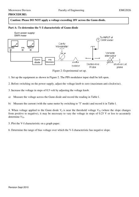
Gunn power supply/<br />
SWR meter<br />
To INPUT <strong>of</strong><br />
GUNN PIN INPUT<br />
Gunn<br />
diode<br />
PIN<br />
Modulator<br />
Figure 2: Experimental set up.<br />
1. Set up the equipment as shown in Figure 2. The PIN modulator input shall be left open.<br />
2. Before switching on the power supply, adjust the voltage knob to zero (maximum anti-clockwise).<br />
3. Increase the voltage in steps <strong>of</strong> 0.5 volt by adjusting the voltage knob.<br />
a) Measure the voltage across the Gunn diode and record the reading in Table l.<br />
b) Measure the current (with the same meter by switching to "I" mode) and record it in Table l.<br />
4. When voltage applied to the Gunn diode V d is near the threshold voltage V Th (where the slope changes<br />
from positive to negative), it may be necessary to vary the voltage in steps <strong>of</strong> 0.25 V or less to accurately<br />
determine V Th .<br />
5. Plot the V-I characteristic on a graph paper.<br />
6. Determine the range <strong>of</strong> bias voltage over which the V-I characteristic has negative slope.<br />
Revision Sept 2010