lab sheet microwave devices emg 2026 - Faculty of Engineering ...
lab sheet microwave devices emg 2026 - Faculty of Engineering ...
lab sheet microwave devices emg 2026 - Faculty of Engineering ...

Create successful ePaper yourself
Turn your PDF publications into a flip-book with our unique Google optimized e-Paper software.
Microwave Devices <strong>Faculty</strong> <strong>of</strong> <strong>Engineering</strong> EMG<strong>2026</strong><br />
MULTIMEDIA UNIVERSITY<br />
FACULTY OF ENGINEERING<br />
LAB SHEET<br />
MICROWAVE DEVICES<br />
EMG <strong>2026</strong><br />
MD 1 - Characteristics <strong>of</strong> Gunn Diode<br />
MD 2 - Characteristics <strong>of</strong> Reflex Klystron<br />
Note: Students are advised to read through this <strong>lab</strong> <strong>sheet</strong> before doing experiment<br />
GUIDELINE FOR LAB REPORT<br />
The <strong>lab</strong>oratory report should include the following:<br />
1. Objective <strong>of</strong> the experiment<br />
2. Procedure<br />
3. Measurement results<br />
4. Discussion <strong>of</strong> the findings<br />
5. Conclusion<br />
The report must be submitted to the Applied EM Lab within 2 weeks from the date <strong>of</strong> the experiment.<br />
Revision Sept 2010
Microwave Devices <strong>Faculty</strong> <strong>of</strong> <strong>Engineering</strong> EMG<strong>2026</strong><br />
OBJECTIVE:<br />
EXPERIMENT 1<br />
CHARACTERISTICS OF GUNN DIODE<br />
1. To identify the principle <strong>of</strong> operation <strong>of</strong> Gunn oscillator.<br />
2. To estimate the voltage current characteristic <strong>of</strong> Gunn diode.<br />
3. To analyse the relationship between voltage across Gunn diode and frequency <strong>of</strong> the <strong>microwave</strong> signal<br />
generated.<br />
4. To analyse the relationship between voltage across Gunn diode and output power.<br />
APPARATUS:<br />
Gunn power supply/SWR meter (737021), Gunn oscillator, PIN modulator, Cavity wavemeter, Isolator,<br />
Slotted line probe, Variable attenuator.<br />
INTRODUCTION:<br />
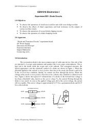
Gunn diode is a type <strong>of</strong> Transferred Electron Device (TED). Material like GaAs exhibit negative differential<br />
mobility (i.e. decrease in carrier velocity with an increase in electric field) when bias voltage is above a<br />
threshold level. This gives rise to negative resistance characteristic <strong>of</strong> the Gunn device (i.e. decrease in<br />
current with an increase in voltage, see Figure 1). The shape <strong>of</strong> the V-I characteristic suggests that the device<br />
may be used as negative resistance amplifier or oscillator.<br />
Unlike other diodes, the Gunn device does not require the presence <strong>of</strong> a p-n junction. The Gunn diode is a<br />
GaAs material with ohmic contacts on the two ends.<br />
GaAs<br />
L<br />
I (mA)<br />
V th V 1<br />
V<br />
Figure 1: V-I characteristic <strong>of</strong> Gunn diode.<br />
Revision Sept 2010
Microwave Devices <strong>Faculty</strong> <strong>of</strong> <strong>Engineering</strong> EMG<strong>2026</strong><br />
A detailed analysis shows that the transit time T = L/v (where L is length <strong>of</strong> sample and v is velocity <strong>of</strong><br />
charge carriers) <strong>of</strong> electron through the GaAs sample should be larger than the domain growth time, T D , to<br />
have the negative resistance characteristic.<br />
The domain growth time is given by T<br />
g<br />
= ε<br />
neµ<br />
. (1)<br />
e<br />
where n is charge carrier density, e the charge <strong>of</strong> an electron, µ e the mobility <strong>of</strong> electron in the negative slope<br />
region <strong>of</strong> the V-I characteristic, and ε the permittivity <strong>of</strong> the GaAs material.<br />
For L/v > T g , the length <strong>of</strong> sample should be<br />
εv<br />
L > .<br />
neµ<br />
e<br />
A more accurate analysis shows that the required criterion is nL > 10 12 cm -2 .<br />
The threshold electric field for GaAs is 3.2x10 5 V/m. The threshold voltage is therefore<br />
V th<br />
= 0 . 32× L<br />
(2)<br />
where L is in micro-meter. For a sample length <strong>of</strong> 30 µ m , the threshold voltage will be 9.6 volts.<br />
The frequency <strong>of</strong> oscillation is related to transit time and hence the length <strong>of</strong> the device. Shorter sample<br />
length will have a higher operating frequency. Since the threshold electric field is fixed, the operating bias<br />
voltage across the device decreases linearly as the design frequency is increased.<br />
When Gunn diode is placed in a resonant cavity, oscillation occurs at the frequency <strong>of</strong> the resonant circuit<br />
rather than at the intrinsic frequency (or transit time frequency). The resonant frequency <strong>of</strong> the resonant<br />
circuit can be several times the intrinsic frequency.<br />
Revision Sept 2010
Microwave Devices <strong>Faculty</strong> <strong>of</strong> <strong>Engineering</strong> EMG<strong>2026</strong><br />
PROCEDURE:<br />
Caution: Please DO NOT apply a voltage exceeding 18V across the Gunn diode.<br />
Part A: To determine the V-I characteristic <strong>of</strong> Gunn diode<br />
Gunn power supply/<br />
SWR meter<br />
To INPUT <strong>of</strong><br />
GUNN PIN INPUT<br />
Gunn<br />
diode<br />
PIN<br />
Modulator<br />
Figure 2: Experimental set up.<br />
1. Set up the equipment as shown in Figure 2. The PIN modulator input shall be left open.<br />
2. Before switching on the power supply, adjust the voltage knob to zero (maximum anti-clockwise).<br />
3. Increase the voltage in steps <strong>of</strong> 0.5 volt by adjusting the voltage knob.<br />
a) Measure the voltage across the Gunn diode and record the reading in Table l.<br />
b) Measure the current (with the same meter by switching to "I" mode) and record it in Table l.<br />
4. When voltage applied to the Gunn diode V d is near the threshold voltage V Th (where the slope changes<br />
from positive to negative), it may be necessary to vary the voltage in steps <strong>of</strong> 0.25 V or less to accurately<br />
determine V Th .<br />
5. Plot the V-I characteristic on a graph paper.<br />
6. Determine the range <strong>of</strong> bias voltage over which the V-I characteristic has negative slope.<br />
Revision Sept 2010
Microwave Devices <strong>Faculty</strong> <strong>of</strong> <strong>Engineering</strong> EMG<strong>2026</strong><br />
Part B: To study the variation <strong>of</strong> power output and frequency with respect to bias voltage<br />
1. Set up the equipment as in Figure 2. Additionally, connect the PIN modulation output <strong>of</strong> the Gunn<br />
power supply to the PIN modulator.<br />
2. Set the applied voltage to the Gunn diode somewhere near the middle <strong>of</strong> the negative slope region <strong>of</strong> the<br />
V-I characteristic.<br />
3. Set the slotted-line probe at about 2-mm protrusion depth and adjust the tuner stub/knob for proper<br />
matching <strong>of</strong> the detector.<br />
4. Set the variable attenuator at 5-mm micrometer setting. (The reading <strong>of</strong> the SWR meter should be<br />
constant when the probe carriage is moved along the slotted-line waveguide.)<br />
5. Adjust the Gunn diode supply voltage until the SWR meter reading is maximised.<br />
6. Select the appropriate V/dB setting. Adjust the zeroing knob <strong>of</strong> the SWR meter so that the needle points<br />
at 0 dB. After this, the zeroing knob should be fixed.<br />
7. Increase the Gunn diode voltage V d to 10V.<br />
8. Measure the frequency using the cavity wavemeter.<br />
(Starting with the cavity wavemeter dial set to maximum clockwise, unscrew the dial slowly. At first there<br />
will be little effect on the SWR meter reading until at one point the power will fall sharply. Read the<br />
frequency indicated on the scale.)<br />
You may also use the alternative method given in Appendix A for <strong>microwave</strong> frequency measurement.<br />
9. Record the applied voltage V d , <strong>microwave</strong> power output in dB, and oscillation frequency in Table 1.<br />
10. Decrease the applied voltage in steps <strong>of</strong> 0.5 V and record the corresponding values <strong>of</strong> power output and<br />
oscillation frequency.<br />
11. Repeat step 10 until V d is lower than the threshold voltage.<br />
12. Plot frequency versus bias voltage.<br />
13. Plot power output versus bias voltage.<br />
14. What is the frequency at which the Gunn oscillator gives maximum power output?<br />
Revision Sept 2010
Microwave Devices <strong>Faculty</strong> <strong>of</strong> <strong>Engineering</strong> EMG<strong>2026</strong><br />
Table 1:<br />
Bias Voltage V d Bias Current Power level (dB) Frequency (GHz)<br />
1<br />
2<br />
3<br />
4<br />
5<br />
6<br />
7<br />
8<br />
9<br />
10<br />
11<br />
12<br />
13<br />
14<br />
15<br />
16<br />
17<br />
18<br />
19<br />
20<br />
21<br />
22<br />
23<br />
24<br />
25<br />
26<br />
27<br />
28<br />
29<br />
30<br />
Revision Sept 2010
Microwave Devices <strong>Faculty</strong> <strong>of</strong> <strong>Engineering</strong> EMG<strong>2026</strong><br />
MARKING SCHEME MD1<br />
(Student can give a result as long as the result is valid)<br />
Part A: To determine the V-I characteristic <strong>of</strong> Gunn diode<br />
5. Plot the V-I characteristic on a graph paper.<br />
(10 marks)<br />
6. Determine the range <strong>of</strong> bias voltage over which the V-I characteristic has negative slope.<br />
(5 marks)<br />
Part B: To study the variation <strong>of</strong> power output and frequency with respect to bias voltage<br />
9. Record the applied voltage V d , <strong>microwave</strong> power output in dB, and oscillation frequency in Table 1.<br />
(10 marks)<br />
12. Plot frequency versus bias voltage. (10 marks)<br />
13. Plot power output versus bias voltage.<br />
(10 marks)<br />
14. What is the frequency at which the Gunn oscillator gives maximum power output?<br />
(5 marks)<br />
(Total: 50 marks)<br />
Revision Sept 2010
Microwave Devices <strong>Faculty</strong> <strong>of</strong> <strong>Engineering</strong> EMG<strong>2026</strong><br />
OBJECTIVE:<br />
EXPERIMENT 2<br />
CHARACTERISTICS OF REFLEX KLYSTRON<br />
1. To identify the principle <strong>of</strong> operation <strong>of</strong> Reflex Klystron.<br />
2. To identify the relationship between repeller voltage and Power output <strong>of</strong> Reflex Klystron.<br />
3. To analyse the relationship between repeller voltage and frequency <strong>of</strong> the <strong>microwave</strong> signal generated by<br />
Reflex Klystron.<br />
4. To analyse the effect <strong>of</strong> cavity size on frequency <strong>of</strong> <strong>microwave</strong> signal generated by Reflex Klystron.<br />
APPARATUS:<br />
Klystron tube, Klystron power supply, Cavity wavemeter, Isolator, Slotted line probe, SWR meter, Matched<br />
load, variable attenuator, and digital multimeter.<br />
INTRODUCTION:<br />
A Reflex Klystron is a <strong>microwave</strong> oscillator with a single cavity (resonator). The construction <strong>of</strong> a reflex<br />
klystron is shown in Figure 1(a). The basic configuration in simplified form as shown in Fig 1(b) is<br />
considered here for understanding the operation <strong>of</strong> Reflex Klystron. The various parts in Figure 1(b) are<br />
(1) Electron Gun; (2) Resonator; (3) Repeller; and (4) Output coupling.<br />
A highly focused beam <strong>of</strong> electrons passing through the resonator gap will be accelerated or decelerated by<br />
the induced current on the resonator. The alternate action <strong>of</strong> increasing and decreasing the electron velocity<br />
will modulate the electron beam into varying dense and sparse <strong>of</strong> electrons referred to as electron bunches.<br />
This electron bunching mechanism is also called intensity modulation or velocity modulation.<br />
The repeller electrode is at a negative potential. It stops the movement <strong>of</strong> the electrons, turn them around,<br />
and send them back through the resonator gap. As the repelled electrons re-enter the resonator, they give up<br />
their kinetik energy. The field excited in the resonator add in phase with the initial modulating field such that<br />
it reinforce the next wave <strong>of</strong> electron bunching. As a result, this energy serves as a regenerative feedback to<br />
sustain the oscillation at the resonant frequency <strong>of</strong> the resonator. This is the case only if the repeller voltage<br />
is set such that the travel time, t o , for the electrons to complete their travel through the gap, turn around, and<br />
back through the gap satisfy the following condition:<br />
t o<br />
⎨<br />
⎧ 3 = n + T<br />
⎩ 4⎭ ⎬⎫<br />
n = 1,2,3,…. (1)<br />
where T is the period <strong>of</strong> the RF waveform.<br />
If the voltage between the resonator and the repeller is V r , and the distance is d, the deceleration or<br />
retardation experienced by the electron may be expressed as<br />
eVr d<br />
a = /<br />
(2)<br />
m<br />
Revision Sept 2010
Microwave Devices <strong>Faculty</strong> <strong>of</strong> <strong>Engineering</strong> EMG<strong>2026</strong><br />
where e is charge <strong>of</strong> electron and m mass <strong>of</strong> electron. If an electron leaves the resonator with velocity v o , the<br />
displacement <strong>of</strong> the electron from the resonator, at any time t, is<br />
1 x<br />
o<br />
− at<br />
2<br />
v t<br />
2<br />
= (3)<br />
This equation can be used to calculate the travel time t o taken by the electron to return to the resonator.<br />
t<br />
r<br />
2v<br />
o<br />
= =<br />
x=<br />
0<br />
a<br />
2v<br />
o<br />
eV<br />
md<br />
r<br />
(4)<br />
Bunching phenomenon in Reflex Klystron<br />
Bunching phenomenon in a reflex Klystron can be visualised by studying the electron trajectories in the<br />
region between the resonator and the repeller. The parabolic trajectories given by equation (3) are shown in<br />
Figure 2.<br />
Let us consider an electron A which passes through the resonator gap with velocity v o when the RF voltage<br />
at the resonator is zero (changing from positive to negative). This electron returns to the resonator at a time t r<br />
later. Another electron B passes through the gap earlier. Because the RF voltage is positive at this instant, the<br />
initial velocity v b for electron B is higher than the initial velocity <strong>of</strong> electron A (v b > v o ). Thus electron B<br />
would travel further towards the repeller and take a longer time to return back to the resonator. It will then<br />
bunch with electron A. Similarly, an electron C that passes through the gap after A emerges with a lower<br />
initial velocity and therefore takes less time to return to the resonator. Electron C catches up with electron A<br />
and bunch with electrons A and B.<br />
The electron bunches formed as described above would deliver power to the resonator if they pass through<br />
the resonator at an instant when the field in the resonator retards the bunch. Referring to Figure 2, we note<br />
that this happens when t o = (3/4) T.<br />
In general, oscillation will occur when the condition in equation (1) is satisfied. Thus there are several values<br />
<strong>of</strong> repeller voltage V r that satisfy the oscillation condition. These values correspond to various modes <strong>of</strong><br />
operation. A particular mode <strong>of</strong> operation may be selected by a choice <strong>of</strong> repeller voltage. Figure 3 shows the<br />
power output versus repeller voltage for various modes <strong>of</strong> operation (called the reflex Klystron mode curves<br />
or mode characteristics). The mode corresponding to n = l occurs at maximum negative repeller voltage. For<br />
n = 0, the gain mechanism is usually not strong enough to overcome system losses. Higher order modes (n ><br />
1) may present at lower repeller voltages. Frequency versus repeller voltage variations is also shown in<br />
Figure 3.<br />
Revision Sept 2010
Microwave Devices <strong>Faculty</strong> <strong>of</strong> <strong>Engineering</strong> EMG<strong>2026</strong><br />
1<br />
2<br />
d<br />
3<br />
4<br />
V a<br />
(b)<br />
V r<br />
(a)<br />
Figure 1: (a) Construction <strong>of</strong> Reflex Klystron and (b) the simplified diagram.<br />
x o<br />
Repeller<br />
d<br />
Resonator gap<br />
B A C<br />
t o<br />
t<br />
RF voltage<br />
t<br />
3T/4<br />
Figure 2: Bunching phenomenon in Reflex Klystron.<br />
Revision Sept 2010
Microwave Devices <strong>Faculty</strong> <strong>of</strong> <strong>Engineering</strong> EMG<strong>2026</strong><br />
RF frequency<br />
V r<br />
n = 1<br />
Output power<br />
n = 3<br />
n = 2<br />
Repeller voltage<br />
V r<br />
Figure 3: Mode characteristics <strong>of</strong> Reflex Klystron.<br />
Cavity<br />
Wavemeter<br />
SWR meter<br />
Variable<br />
attenuator<br />
Klystron<br />
Source<br />
Isolator<br />
Slotted-line<br />
Probe<br />
short-circuit<br />
plane<br />
Figure 4: Schematic <strong>of</strong> the experiment set up.<br />
Revision Sept 2010
Microwave Devices <strong>Faculty</strong> <strong>of</strong> <strong>Engineering</strong> EMG<strong>2026</strong><br />
PROCEDURE:<br />
CAUTION 1: The RF power levels in the following experiments are not harmful, but a human eye<br />
may be damaged by low level <strong>of</strong> radiation. Do not look into the waveguide at any time when the<br />
equipment are on.<br />
CAUTION 2: Klystron tube get extremely hot when it is operated and must not be handled by hand.<br />
Measurement <strong>of</strong> Frequency and power with variation in repeller voltage<br />
1. Set up the equipment as shown in Figure 4. Switch on the power supply and RF output. Wait a few<br />
seconds for the Klystron tube to warm up.<br />
2. Select squarewave modulation. Set the modulation level to maximum. Adjust the repeller voltage to<br />
maximum and then decrease it slowly until the largest deflection (maximum power) is indicated on the SWR<br />
meter.<br />
3. Adjust the modulation frequency so that the SWR meter deflection is further maximised.<br />
4. Set the slotted-line probe at about 2-mm protrusion depth and adjust the tuner stub/knob for proper<br />
matching <strong>of</strong> the detector.<br />
5. Set the variable attenuator at 5-mm micrometer setting. (The reading <strong>of</strong> the SWR meter should be<br />
constant when the probe carriage is moved along the slotted-line waveguide.)<br />
6. Adjust the gain knob <strong>of</strong> the SWR meter so that the needle points at 0 dB. After this, the zeroing knob<br />
should be fixed.<br />
7. Measure the repeller voltage from the connector at the rear panel <strong>of</strong> the Klystron power supply using a<br />
multimeter and record the reading. The multimeter reading shall be multiplied by 10x to give the repeller<br />
voltage.<br />
8. Measure the frequency using the cavity wavemeter and record the result.<br />
(Starting with the cavity wavemeter dial set to maximum clockwise, unscrew the dial slowly. At first there<br />
will be little effect on the SWR meter reading until at one point the power will fall sharply. Read the<br />
frequency indicated on the scale.)<br />
You may also use the alternative method given in Appendix A for <strong>microwave</strong> frequency measurement.<br />
9. Vary the repeller voltage.<br />
10. Measure the repeller voltage and record the reading.<br />
11. Measure the frequency using the cavity wave meter and record the reading.<br />
12. Repeat steps 9-11 for the full range <strong>of</strong> repeller voltage.<br />
13. Plot relative power level in dB versus repeller voltage.<br />
14. Plot frequency versus repeller voltage.<br />
Revision Sept 2010
Microwave Devices <strong>Faculty</strong> <strong>of</strong> <strong>Engineering</strong> EMG<strong>2026</strong><br />
Measurement data:<br />
1<br />
Repeller voltage (multimeter<br />
reading × 10V)<br />
Relative output power (dB)<br />
Frequency (GHz)<br />
2<br />
3<br />
4<br />
5<br />
6<br />
7<br />
8<br />
9<br />
10<br />
11<br />
12<br />
13<br />
14<br />
15<br />
16<br />
17<br />
18<br />
19<br />
20<br />
21<br />
22<br />
23<br />
24<br />
25<br />
26<br />
27<br />
28<br />
29<br />
30<br />
Revision Sept 2010
Microwave Devices <strong>Faculty</strong> <strong>of</strong> <strong>Engineering</strong> EMG<strong>2026</strong><br />
Appendix A<br />
Microwave Frequency Measurement Using Slotted-line Probe<br />
1. Adjust the variable attenuator to obtain an SWR greater than 3.<br />
2. Move the probe along the waveguide to find two successive minimum points. Record the positions <strong>of</strong><br />
these two points (x 1 and x 2 ) from the Vernier scale <strong>of</strong> the slotted-line waveguide. Determine the<br />
waveguide wavelength λ g .<br />
Power<br />
λ g = 2d<br />
x1<br />
d<br />
x2<br />
Distance<br />
Fig. A1: Standing wave pattern.<br />
3. Calculate the free-space wavelength λ o using equation A1. The inner dimensions <strong>of</strong> the waveguide is<br />
given as a=2.2870cm and b=1.0160cm. The cut<strong>of</strong>f waveleght for TE 10 mode is λ c = 2a.<br />
1 1 1<br />
2<br />
=<br />
2<br />
+<br />
2<br />
(A1)<br />
λ λ λ<br />
o g c<br />
4. Calculate the <strong>microwave</strong> frequency f o = c/λ o .<br />
Revision Sept 2010
Microwave Devices <strong>Faculty</strong> <strong>of</strong> <strong>Engineering</strong> EMG<strong>2026</strong><br />
MARKING SCHEME MD2<br />
(Student can give a result as long as the result is valid)<br />
Measurement <strong>of</strong> Frequency and power with variation in repeller voltage<br />
1. Measurement data Table. (10 marks)<br />
13. Plot relative power level in dB versus repeller voltage.<br />
(20 marks)<br />
14. Plot frequency versus repeller voltage.<br />
(20 marks)<br />
(Total: 50 marks)<br />
Revision Sept 2010