lab sheet microwave devices emg 2026 - Faculty of Engineering ...
lab sheet microwave devices emg 2026 - Faculty of Engineering ...
lab sheet microwave devices emg 2026 - Faculty of Engineering ...

You also want an ePaper? Increase the reach of your titles
YUMPU automatically turns print PDFs into web optimized ePapers that Google loves.
Microwave Devices <strong>Faculty</strong> <strong>of</strong> <strong>Engineering</strong> EMG<strong>2026</strong><br />
OBJECTIVE:<br />
EXPERIMENT 2<br />
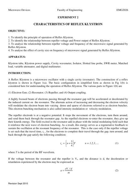
CHARACTERISTICS OF REFLEX KLYSTRON<br />
1. To identify the principle <strong>of</strong> operation <strong>of</strong> Reflex Klystron.<br />
2. To identify the relationship between repeller voltage and Power output <strong>of</strong> Reflex Klystron.<br />
3. To analyse the relationship between repeller voltage and frequency <strong>of</strong> the <strong>microwave</strong> signal generated by<br />
Reflex Klystron.<br />
4. To analyse the effect <strong>of</strong> cavity size on frequency <strong>of</strong> <strong>microwave</strong> signal generated by Reflex Klystron.<br />
APPARATUS:<br />
Klystron tube, Klystron power supply, Cavity wavemeter, Isolator, Slotted line probe, SWR meter, Matched<br />
load, variable attenuator, and digital multimeter.<br />
INTRODUCTION:<br />
A Reflex Klystron is a <strong>microwave</strong> oscillator with a single cavity (resonator). The construction <strong>of</strong> a reflex<br />
klystron is shown in Figure 1(a). The basic configuration in simplified form as shown in Fig 1(b) is<br />
considered here for understanding the operation <strong>of</strong> Reflex Klystron. The various parts in Figure 1(b) are<br />
(1) Electron Gun; (2) Resonator; (3) Repeller; and (4) Output coupling.<br />
A highly focused beam <strong>of</strong> electrons passing through the resonator gap will be accelerated or decelerated by<br />
the induced current on the resonator. The alternate action <strong>of</strong> increasing and decreasing the electron velocity<br />
will modulate the electron beam into varying dense and sparse <strong>of</strong> electrons referred to as electron bunches.<br />
This electron bunching mechanism is also called intensity modulation or velocity modulation.<br />
The repeller electrode is at a negative potential. It stops the movement <strong>of</strong> the electrons, turn them around,<br />
and send them back through the resonator gap. As the repelled electrons re-enter the resonator, they give up<br />
their kinetik energy. The field excited in the resonator add in phase with the initial modulating field such that<br />
it reinforce the next wave <strong>of</strong> electron bunching. As a result, this energy serves as a regenerative feedback to<br />
sustain the oscillation at the resonant frequency <strong>of</strong> the resonator. This is the case only if the repeller voltage<br />
is set such that the travel time, t o , for the electrons to complete their travel through the gap, turn around, and<br />
back through the gap satisfy the following condition:<br />
t o<br />
⎨<br />
⎧ 3 = n + T<br />
⎩ 4⎭ ⎬⎫<br />
n = 1,2,3,…. (1)<br />
where T is the period <strong>of</strong> the RF waveform.<br />
If the voltage between the resonator and the repeller is V r , and the distance is d, the deceleration or<br />
retardation experienced by the electron may be expressed as<br />
eVr d<br />
a = /<br />
(2)<br />
m<br />
Revision Sept 2010