

Aerodynamic Stability and Performance of Next-Generation ...
Aerodynamic Stability and Performance of Next-Generation ...
Aerodynamic Stability and Performance of Next-Generation ...

You also want an ePaper? Increase the reach of your titles
YUMPU automatically turns print PDFs into web optimized ePapers that Google loves.
stability behavior that were more attractive than that <strong>of</strong> the DGB. Disksail configurations DS-2 <strong>and</strong> DS-3, however,<br />
exhibited significantly greater tangential force <strong>and</strong> equivalent stability behavior relative to the DGB. The starsail<br />
exhibited different behavior from the ringsail <strong>and</strong> disksail, but it did not appear to improve upon the DGB<br />
performance. Selection <strong>of</strong> a final canopy design is not presented due to lack <strong>of</strong> uncertainty analyses <strong>and</strong> the absence<br />
<strong>of</strong> data from a final wind tunnel test entry, which was not processed in time for this publication.<br />
Appendix<br />
Downloaded by GEORGIA INST OF TECHNOLOGY on April 1, 2013 | http://arc.aiaa.org | DOI: 10.2514/6.2013-1356<br />
A. Calculating the Total Angle <strong>of</strong> Attack<br />
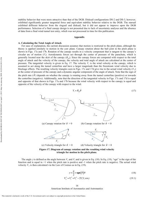
For ease <strong>of</strong> explanation, the current discussion assumes that motion is restricted to the pitch plane, although the<br />
theory is applied similarly to motion in the yaw plane. Canopy rotation about the ball joint in the pitch plane is<br />
shown in Figs. 17a <strong>and</strong> 17b. Rotation <strong>of</strong> the canopy results in a velocity component that is tangent to the canopy’s<br />
circular arc <strong>of</strong> motion (V t ). <strong>Aerodynamic</strong> forces act through the center <strong>of</strong> pressure <strong>of</strong> the parachute, which is<br />
generally located near the skirt <strong>of</strong> the canopy (R cp ). Since the canopy forces are computed with respect to the total<br />
angle <strong>of</strong> attack <strong>and</strong> the velocity <strong>of</strong> the canopy, the velocity <strong>and</strong> total angle <strong>of</strong> attack are calculated at the center <strong>of</strong><br />
pressure. The tangential velocity is given in Eq. 17. The velocity V c is the wind velocity at the canopy, which is<br />
assumed to act along the tunnel centerline <strong>and</strong> have a larger magnitude than the freestream wind velocity due to<br />
blockage effects. The resulting velocity triangles seen in Figs. 17c <strong>and</strong> 17d give rise to the actual wind velocity (V w )<br />
at the center <strong>of</strong> pressure <strong>of</strong> the canopy <strong>and</strong> a dynamic angular component <strong>of</strong> the angle <strong>of</strong> attack. Note that the sign <strong>of</strong><br />
the pitch rate ( θ ) depends on whether the canopy is rotating away from the tunnel centerline (positive) or towards<br />
the centerline (negative). Additionally, note that the direction <strong>of</strong> the tangential velocity in Figs. 17c <strong>and</strong> 17d is equal<br />
<strong>and</strong> opposite <strong>of</strong> that shown in Figs. 17a <strong>and</strong> 17b because the wind velocity with respect to the canopy is equal <strong>and</strong><br />
opposite <strong>of</strong> the velocity <strong>of</strong> the canopy with respect to the wind.<br />
V t<br />
= R cp θ (17)<br />
(a) Canopy rotation for > 0 (b) Canopy rotation for < 0<br />
(c) Velocity triangle for > 0 (d) Velocity triangle for < 0<br />
Figure 17. Diagram <strong>of</strong> canopy rotation <strong>and</strong> the resulting wind velocity<br />
triangle for motion in the pitch plane.<br />
The angle γ is defined as the angle between V c <strong>and</strong> V t <strong>and</strong> is given in Eq. (18). In Eq. (18), “sgn” is the sign <strong>of</strong> the<br />
function <strong>and</strong> is equal to +1 when the pitch rate is positive <strong>and</strong> -1 when the pitch rate is negative. The actual wind<br />
velocity V w is then calculated via the Law <strong>of</strong> Cosines as in Eq. (19).<br />
γ = π 2 + sgn ( θ )θ (18)<br />
V w 2 = V c 2 +V t 2 − 2V c<br />
V t<br />
cosγ (19.1)<br />
16<br />
American Institute <strong>of</strong> Aeronautics <strong>and</strong> Astronautics<br />
This material is declared a work <strong>of</strong> the U.S. Government <strong>and</strong> is not subject to copyright protection in the United States.


