

Aerodynamic Stability and Performance of Next-Generation ...
Aerodynamic Stability and Performance of Next-Generation ...
Aerodynamic Stability and Performance of Next-Generation ...

You also want an ePaper? Increase the reach of your titles
YUMPU automatically turns print PDFs into web optimized ePapers that Google loves.
Downloaded by GEORGIA INST OF TECHNOLOGY on April 1, 2013 | http://arc.aiaa.org | DOI: 10.2514/6.2013-1356<br />
1) Disk-gap-b<strong>and</strong>: DGB canopies are constructed by separating a flat circular disk <strong>and</strong> a cylindrical b<strong>and</strong> <strong>of</strong><br />
fabric by an open gap to aid in stability. The DGB canopy serves as the reference by which all <strong>of</strong> the nextgeneration<br />
parachutes are assessed. Two configurations were tested:<br />
a. DGB-1: a flight spare <strong>of</strong> the parachute used for the Mars Phoenix Scout l<strong>and</strong>er mission,<br />
constructed using MIL-C-7020 Type I nylon, which has a permeability <strong>of</strong> approximately 100<br />
ft 3 /min/ft 2 . For this canopy, the contribution from fabric porosity is non-negligible <strong>and</strong> the total<br />
porosity was calculated to be between 12-18%.<br />
b. DGB-2: a replica <strong>of</strong> the Phoenix DGB constructed using F-111 nylon. This test article is shown in<br />
Fig. 1a.<br />
2) Ringsail: ringsail parachutes are modifications <strong>of</strong> ringslot parachutes that add fullness to the fabric panels<br />
<strong>and</strong> allow for more airflow through the canopy. Five configurations were tested:<br />
a. RS-0: a subscale version <strong>of</strong> a Ringsail parachute tested by JPL in 2005. 4 A picture <strong>of</strong> this test<br />
article is shown in Fig. 1b.<br />
b. RS-1: the RS-0 canopy with two-thirds <strong>of</strong> ring 19 removed.<br />
c. RS-2: the RS-0 canopy with 27% <strong>of</strong> rings 17, 18 <strong>and</strong> 19 removed.<br />
d. RS-3: the RS-0 canopy with all <strong>of</strong> ring 19 removed.<br />
e. RS-4: the RS-0 canopy with all <strong>of</strong> rings 18 <strong>and</strong> 19 removed.<br />
3) Disksail: the disksail canopy is a modification <strong>of</strong> the Ringsail canopy that replaces the first ten rings around<br />
the canopy vent with a flat circular disk. The goal <strong>of</strong> this configuration was to decrease geometric porosity in<br />
the crown <strong>of</strong> the parachute to increase drag <strong>and</strong> allow that porosity to be redistributed to other portions <strong>of</strong> the<br />
canopy. Five configurations were tested:<br />
a. DS-1: the disksail as described above <strong>and</strong> as shown in Fig 1c.<br />
b. DS-2: the DS-1 canopy with half <strong>of</strong> ring 11 removed.<br />
c. DS-3: the DS-1 canopy with all <strong>of</strong> ring 11 removed.<br />
d. DS-4: the DS-1 canopy with all <strong>of</strong> ring 11 <strong>and</strong> half <strong>of</strong> ring 17 removed.<br />
e. DS-5: the DS-1 canopy with all <strong>of</strong> ring 11 <strong>and</strong> half <strong>of</strong> rings 17 <strong>and</strong> 18 removed.<br />
4) Starsail: the starsail canopy is a modification <strong>of</strong> the Ringsail where multiple gores are replaced with a solid<br />
material creating a star pattern. The goal <strong>of</strong> this configuration is to change how the geometric porosity is<br />
distributed throughout the canopy to retain drag <strong>and</strong> obtain some desirable stability characteristics. Portions<br />
<strong>of</strong> rings 17-20 were removed to obtain a geometric porosity approximately equal to the DGB. One starsail<br />
configuration was tested <strong>and</strong> is shown in Fig. 1d.<br />
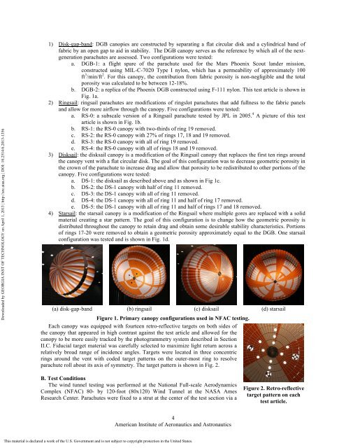
(a) disk-gap-b<strong>and</strong> (b) ringsail (c) disksail (d) starsail<br />
Figure 1. Primary canopy configurations used in NFAC testing.<br />
Each canopy was equipped with fourteen retro-reflective targets on both sides <strong>of</strong><br />
the canopy that appeared in high contrast against the test article <strong>and</strong> allowed for the<br />
canopy to be more easily tracked by the photogrammetry system described in Section<br />
II.C. Fiducial target material was carefully selected to maximize light return across a<br />
relatively broad range <strong>of</strong> incidence angles. Targets were located in three concentric<br />
rings around the vent with coded target patterns on the outer-most ring to resolve<br />
parachute roll about its axis <strong>of</strong> symmetry. The target pattern is shown in Fig. 2.<br />
B. Test Conditions<br />
The wind tunnel testing was performed at the National Full-scale <strong>Aerodynamic</strong>s<br />
Complex (NFAC) 80- by 120-foot (80x120) Wind Tunnel at the NASA Ames<br />
Research Center. Parachutes were fixed to a strut at the center <strong>of</strong> the test section via a<br />
Figure 2. Retro-reflective<br />
target pattern on each<br />
test article.<br />
4<br />
American Institute <strong>of</strong> Aeronautics <strong>and</strong> Astronautics<br />
This material is declared a work <strong>of</strong> the U.S. Government <strong>and</strong> is not subject to copyright protection in the United States.


