

Investigation of Transonic Drag Computations in Aerodynamic ...
Investigation of Transonic Drag Computations in Aerodynamic ...
Investigation of Transonic Drag Computations in Aerodynamic ...

Create successful ePaper yourself
Turn your PDF publications into a flip-book with our unique Google optimized e-Paper software.
<strong>Investigation</strong> <strong>of</strong> <strong>Transonic</strong> <strong>Drag</strong> <strong>Computations</strong> <strong>in</strong> APAS<br />
100 ft.<br />
R 5 ft.<br />
20 ft.<br />
40.6 ft.<br />
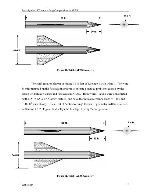
Figure 11. Trial 3 APAS Geometry<br />
The configuration shown <strong>in</strong> Figure 11 is that <strong>of</strong> fuselage 1 with w<strong>in</strong>g 1. The w<strong>in</strong>g<br />
is mid-mounted on the fuselage <strong>in</strong> order to elim<strong>in</strong>ate potential problems caused by the<br />
space left between w<strong>in</strong>gs and fuselages <strong>in</strong> APAS. Both w<strong>in</strong>gs 1 and 2 were constructed<br />
with NACA 65 A 0XX series airfoils, and have theoretical reference areas <strong>of</strong> 1100 and<br />
1000 ft 2 respectively. The effect <strong>of</strong> “coke-bottl<strong>in</strong>g” the trial 3 geometry will be discussed<br />
<strong>in</strong> Section 4.1.7. Figure 12 displays the fuselage 1, w<strong>in</strong>g 2 configuration.<br />
100 ft.<br />
R 5 ft.<br />
20 ft.<br />
34.6 ft.<br />
Figure 12. Trial 4 APAS Geometry<br />
Jeff Miller 12


