Industrial Vane Pumps - Corken
Industrial Vane Pumps - Corken
Industrial Vane Pumps - Corken

You also want an ePaper? Increase the reach of your titles
YUMPU automatically turns print PDFs into web optimized ePapers that Google loves.
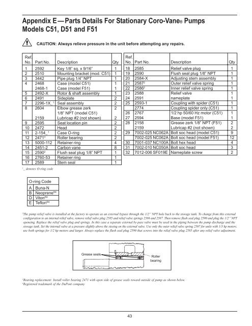
Appendix E — Parts Details For Stationary Coro-<strong>Vane</strong>® <strong>Pumps</strong><br />
Models C51, D51 and F51<br />
CAUTION: Always relieve pressure in the unit before attempting any repairs.<br />
Ref.<br />
No.<br />
1<br />
2<br />
3<br />
4<br />
5<br />
6<br />
7<br />
8<br />
9<br />
10<br />
11<br />
12<br />
13<br />
14<br />
15<br />
16<br />
17<br />
_ denotes<br />
O-ring<br />
A<br />
B<br />
D<br />
E<br />
Part No.<br />
2592<br />
2510<br />
3442<br />
2468<br />
2468-1<br />
2492-X<br />
2491<br />
2296-1X_<br />
2604<br />
2159<br />
2595<br />
2472<br />
2-154_ 1<br />
2471 3<br />
5000-112<br />
2451-2<br />
2590 2<br />
2760-53<br />
2589<br />
O-ring code<br />
Code<br />
Buna-N<br />
Neoprene<br />
Viton ®4<br />
Teflon ®4 Description<br />
Key 1/8” sq.<br />
Mounting bracket<br />
Pipe plug 1/4”<br />
Case (model<br />
Case (model<br />
Rotor & shaft<br />
Sideplate<br />
Seal assembly<br />
Elbow grease<br />
1/8” NPT (model<br />
Lubricap #2<br />
Seat location<br />
Head<br />
Case O-ring<br />
Roller bearing<br />
Retainer ring<br />
Carbon vane<br />
Flush seal plug<br />
Retainer ring<br />
Stem seal<br />
Qty<br />
1<br />
1<br />
1<br />
1<br />
1<br />
1<br />
2<br />
2<br />
2<br />
2<br />
2<br />
2<br />
2<br />
2<br />
4<br />
8<br />
1<br />
1<br />
1<br />
Ref.<br />
No. Part No.<br />
18 2585<br />
19 2590<br />
20 2584-X<br />
21 2587 2<br />
22 2586 2<br />
23 2588<br />
24 2591<br />
25 2593-1<br />
2774<br />
26 2767<br />
27 2594<br />
28 2158<br />
2159<br />
29 7002-025<br />
7002-025<br />
30 7001-037<br />
31 7002-010<br />
32 7012-006<br />
Description<br />
Relief valve<br />
Flush seal plug<br />
Adjusting stem<br />
Outer relief<br />
Inner relief valve<br />
Relief valve<br />
nameplate<br />
Coupling with<br />
Coupling spider<br />
1/2 hp 50/60<br />
Base (model<br />
Grease zerk<br />
Lubricap #2<br />
Bolt soc head<br />
Bolt soc head<br />
Bolt hex head<br />
Bolt soc head<br />
Nameplate<br />
Qty<br />
1<br />
1<br />
1<br />
1<br />
1<br />
1<br />
1<br />
1<br />
1<br />
1<br />
1<br />
2<br />
2<br />
9<br />
12<br />
4<br />
3<br />
2<br />
x 9/16” plug<br />
(mod. C51) 1/8” NPT<br />
NPT assembly<br />
C51) valve spring<br />
F51) spring<br />
assembly 1 spider (C51)<br />
zerk only (C51)<br />
C51)<br />
Hz motor (C51)<br />
(not shown) F51)<br />
pin 1/8” NPT (F51)<br />
(not shown)<br />
NC062A (model C51)<br />
NC062A (model F51)<br />
NC100A<br />
NC050A<br />
1/8” NPT SF019E screw<br />
1 ®4<br />
2<br />
The pump relief valve is installed at the factory to operate as an external bypass through the 1/2” NPT hole back to the storage tank. To change from this external<br />
configuration to an internal relief valve, remove relief valve plug 2585 and relief valve springs 2586 and 2587. Then remove flush seal plug 2590 and plug the 1/2” NPT<br />
openeing. Replace the relief valve plug and springs. In this case a separate external by-pass valve must be used in the piping between the pump discharge and the<br />
storage tank. Set the internal valve at a pressure slightly above the steeing on the external valve. Use only the outer relief valve spring 2587 for units with 1/3 hp motors.<br />
use both springs for 1/2 hp motors and larger. Always replace the flush seal plug 2590 that screws into the relief valve plug 2585 after any relief valve adjustment.<br />
3<br />
Bearing replacement: Install roller bearing 2471 with open side of grease seals toward outside of pump as shown below.<br />
4<br />
Registered trademark of the DuPont company<br />
43