Industrial Vane Pumps - Corken
Industrial Vane Pumps - Corken
Industrial Vane Pumps - Corken

Create successful ePaper yourself
Turn your PDF publications into a flip-book with our unique Google optimized e-Paper software.
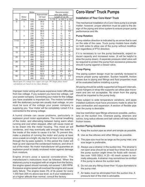
Motor Recommended<br />
Approximate wire size, AWG 1<br />
Motor full load Length of run (ft)<br />
Hp phase Volts amperes 0–100 to 200 to 300<br />
3 1 115 34.0 6 4 2<br />
220 17.0 12 8 8<br />
3 230 9.6 12 12 12<br />
460 4.8 12 12 12<br />
5 1 115 56.0 4 1 1/0<br />
230 28.0 10 6 4<br />
3 230 15.2 12 12 10<br />
460 7.6 12 12 12<br />
7-1/2 1 230 40.0 8 6 4<br />
3 230 22.0 10 10 8<br />
450 11.0 12 12 12<br />
10 3 230 28.0 8 8 8<br />
460 14.0 12 12 12<br />
15 3 230 42.0 6 6 6<br />
460 21.0 10 10 10<br />
20 3 230 54.0 4 4 4<br />
460 27.0 8 8 8<br />
25 3 230 68.0 2 2 2<br />
460 34.0 6 6 6<br />
30 3 230 80.0 1 1 1<br />
460 40.0 6 6 6<br />
40 3 230 100.0 2/0 2/0 2/0<br />
460 52.0 4 4 4<br />
50 3 230 130.0 3/0 3/0 3/0<br />
460 65.0 2 2 2<br />
1<br />
Based upon 3% voltage loss copper wire type TW. Single phase motor<br />
calculations are based on two times distance.<br />
Improper motor wiring will cause expensive motor difficulties<br />
from low voltage. If you suspect you have low voltage, call<br />
your power company. Connecting your motor for the voltage<br />
you have available is important too. The motors furnished<br />
with the stationary pumps are usually dual voltage, so you<br />
must be sure of the voltage your power company is<br />
supplying you. Your motor will be completely ruined if it is<br />
connected to the wrong voltage.<br />
A humid climate can cause problems, particularly in<br />
explosion proof motor applications. The normal breathing<br />
of the motor, and alternating between being warm when<br />
running and cool when stopped, often will cause moist air<br />
to be drawn into the motor housing. This moist air will<br />
condense, and may eventually add enough free water to<br />
the inside of the motor to cause it to fail. To prevent this,<br />
make a practice of running the motor and pump at least<br />
once a week on a bright, dry day for an hour or so (pumping<br />
through the by-pass system). In this period the motor will<br />
heat up and vaporize the condensed moisture, and drive it<br />
out of the motor. No motor manufacturer will guarantee an<br />
explosion-proof or totally enclosed motor against damage<br />
from moisture.<br />
Engine drivers pose a special consideration. The<br />
manufacturer’s instructions must be followed. When the<br />
stationary pump is equipped with an engine from the factory,<br />
the engine speed should normally not exceed 1,800 RPM.<br />
Excessive engine speed will overload the engine and cause<br />
early failure. The engine loses 3% of its power for every<br />
1,000 feet (305 m) above sea level, so if your installation is<br />
at a higher altitude than normal, consult the factory.<br />
Coro-<strong>Vane</strong> ® Truck <strong>Pumps</strong><br />
Installation of Your Coro-<strong>Vane</strong> ® Truck<br />
The mechanical installation of a Coro-<strong>Vane</strong> pump is a simple<br />
matter; however, proper attention must be paid to the design<br />
of the piping and drive system to ensure proper pump<br />
performance and life.<br />
Pump Rotation<br />
Pump rotation direction is indicated by an arrow that is cast<br />
on the side of the case. Truck pump models have shafts<br />
on both sides to allow use of the pump without modification<br />
regardless of PTO direction.<br />
If it is necessary to run the pump backwards, expect reduced<br />
capacity and increased noise. (It will be helpful to<br />
slow the pump down). A separate pressure relief valve will<br />
be required to protect the pump from excessive pressures<br />
should it pump against a closed valve.<br />
Pump Piping<br />
The piping system design must be carefully reviewed to<br />
ensure proper pump operation. Suction head/lift, friction<br />
losses due to piping and fittings and fluid properties must<br />
all be evaluated before installing a pump.<br />
All piping should be solidly supported at frequent intervals.<br />
Loose hangers or strap-like supports can allow pipe movement<br />
and are not acceptable. No strain from the piping<br />
should be imparted to the pump body.<br />
Pipes subject to wide temperature variations, and pipes<br />
installed outdoors must have provisions made to allow for<br />
pipe contraction and expansion. A section of flexible pipe<br />
near the pump is desirable.<br />
Use low restriction type fittings whenever possible, particularly<br />
on the suction line. Oversize piping, strainers and<br />
valves; long radius elbows and ball valves will help reduce<br />
friction losses.<br />
Suction Piping Guidelines<br />
A. Keep the suction pipe as short and simple as possible.<br />
B. Use as few elbows and other fittings as possible.<br />
C. The pipe size must be as large as the pump inlet; one<br />
size larger is preferable.<br />
D. Always use a strainer in the suction line. The strainer’s<br />
net open area should be at least four times the size of<br />
the pump suction (eight times for fluids with viscosities<br />
over 1000 SSU). A 20– 40 mesh screen is normally<br />
adequate. A strainer may sometimes be omitted<br />
if the pump is above the suction tank.<br />
E. Do not use any fitting closer than 10 pipe diameters to<br />
the pump inlet.<br />
F. Air leaks must be eliminated from the suction line. A<br />
pressure test of the inlet is advisable.<br />
7