Principles of Your Coro-<strong>Vane</strong> ® Pump The <strong>Corken</strong> Coro-<strong>Vane</strong>® pumps are a special type of rotary positive displacement pump, known as a sliding vane pump. The sliding vane pump has many of the positive displacement advantages of the gear pump, plus the ability to compensate for wear, and operate at a lower noise level. The sliding vane pump consists of a rotor turning in a cam (liner) machined eccentrically in relation to the rotor; thereby displacing the liquid trapped between the rotor, cam and vanes. The <strong>Corken</strong> Coro-<strong>Vane</strong>® pumps are made with vanes produced from advanced polymers which exhibit extremely low coefficients of friction. The vanes are self-adjusting for wear which gives the pump long life. Exclusive Features of Your Coro-<strong>Vane</strong> ® Pump The pumping of volatile liquids is one of the most difficult of all pumping jobs, so more attention must be given to the design and manufacture of the pump and to its installation and operation. In addition to being especially suited for handling volatile liquids, your Coro-<strong>Vane</strong>® pump has a number of features to help make it more easily operated and maintained. Coro-<strong>Vane</strong> ® Stationary <strong>Pumps</strong> Installation of Your Coro-<strong>Vane</strong> ® Stationary Pump The installation of the Coro-<strong>Vane</strong> ® pump is simple. However, in order for the pump to deliver optimum performance, the principles discussed in this book should be followed. The piping details are furnished to illustrate methods proved by hundreds of installations. Your own needs may require slight variations, but every effort should be made to follow the recommendations identified in this manual. No pump can discharge more liquid than it receives, so the pump location and the inlet piping must be given careful attention. If the inlet piping is inadequate to supply the demand of the pump, you may have trouble. In the piping diagram shown in figure 2, page 5, never use a piping size smaller than the inlet of the pump. For the transfer of flammable liquids like LPG, the pump must be installed according to the applicable local safety and health regulations. The installer and/or the user must take into account the following: • The pump must be located as near as possible to the storage tank. The complete inlet line, including the vertical line from the tank must not exceed twelve feet (3.7 m) in length. The industrial style Coro-<strong>Vane</strong>® pump is manufactured in six models: the Models C51 and F51 small stationary and the Models 0521/0522, 0721/0722, 1021/1022, 1321/1322 and 1521/1522 stationary pumps. The F Models (e.g. CPBF1021) have ANSI flanged connections. The CASE AND HEADS are made of cast or ductile iron. The VANES are manufactured of advanced polymers to provide excellent life and quiet operation. After long service, the vanes are simply and inexpensively replaced. Both the CAM and the SIDEPLATES are easily replaced should the need arise. The MECHANICAL SEAL is designed for longer life under greater loads and may be inspected or replaced without disturbing the piping of the pump. No special tools are needed. BEARINGS are heavy-duty roller type for long bearing life. PRESSURE GAUGE connections, 1/4" pipe thread, are provided. The PUMP NOZZLES on Models 521, 721, 1021, 1321 and 1521 equipped with flanges to simplify piping. It is not necessary to provide unions in the piping system near the pump because the flanges serve this purpose. The RELIEF VALVE is built-in as part of the pump on all NPT models and is adjustable under pressure. Figure 1: Concrete Foundation Diagram • The bottom of the tank must be no less than two feet (0.6 m) above the pump inlet nozzle, with four feet (1.2m) considered standard. • The foundation for the pump is important. The foundation must be firm, level and preferably made of concrete. The suggestions in figure 1 should be observed. • Potential risk due to local conditions regarding the installation and operation (e.g. poor ventilation and additional risks due to other elements in the vicinity, etc.). • Qualification of the personnel. • Type of liquid being transferred. NOTE: EVEN WITH THIS INTERNAL SAFETY VALVE, AN EXTERNAL BY-PASS VALVE MUST BE INSTALLED. 4
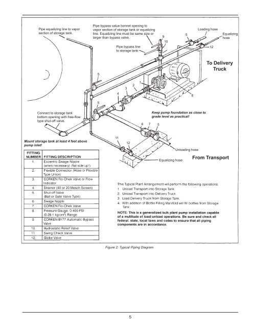
(40 or 20 Mesch Screen) Figure 2: Typical Piping Diagram 5