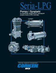
Industrial Vane Pumps - Corken
Industrial Vane Pumps - Corken
Industrial Vane Pumps - Corken

Create successful ePaper yourself
Turn your PDF publications into a flip-book with our unique Google optimized e-Paper software.
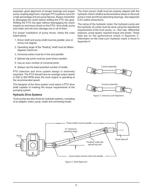
expected, good alignment of hanger bearings and proper<br />
pump coupling alignment. Improper PTO systems count for<br />
a high percentage of truck pump failures. Always remember<br />
to disengage the clutch before shifting the PTO into gear.<br />
Shifting the PTO into gear without disengaging the clutch<br />
imparts an enormous shock on the PTO, drive shaft, pump<br />
and meter and will soon damage one or all of them.<br />
For proper installation of pump drives, follow the rules<br />
listed below:<br />
1. Driver shaft and pump shaft must be parallel, plus or<br />
minus one degree.<br />
2. Operating angle of the ''floating'' shaft must be fifteen<br />
degrees maximum.<br />
3. Universal yokes must be in line and parallel.<br />
4. Splined slip joints must be used where needed.<br />
5. Use an even number of universal joints.<br />
6. Always use the least practical number of shafts.<br />
PTO selection and drive system design is extremely<br />
important. The PTO should have an average output speed<br />
of 500 to 800 RPM when the truck engine is operating at<br />
the recommended speed.<br />
The designer of the drive system must select a PTO drive<br />
shaft capable of meeting the torque requirements of the<br />
pumping system.<br />
Hydraulic Drive Systems<br />
Truck pumps are also driven by hydraulic systems, consisting<br />
of an adaptor, motor, pump, cooler and connecting hoses.<br />
The truck pump’s shaft must be properly aligned with the<br />
hydraulic motor’s shaft to avoid excessive stress on the truck<br />
pump’s main and thrust absorbing bearings. See Appendix<br />
D for outline dimensions.<br />
The sizing of the hydraulic motor, the hydraulic pump and<br />
the hydraulic oil cooler must be done using the operational<br />
requirements of the truck pump, i.e., flow rate, differential<br />
pressure, pump speed, required torque and power. These<br />
data are on the performance charts in Appendix C.<br />
Information on the Char-Lynn hydraulic motor is found in<br />
Appendix H.<br />
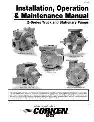
Figure 3: Universal Joint Alignment<br />
Figure 4: Shaft Alignment<br />
9