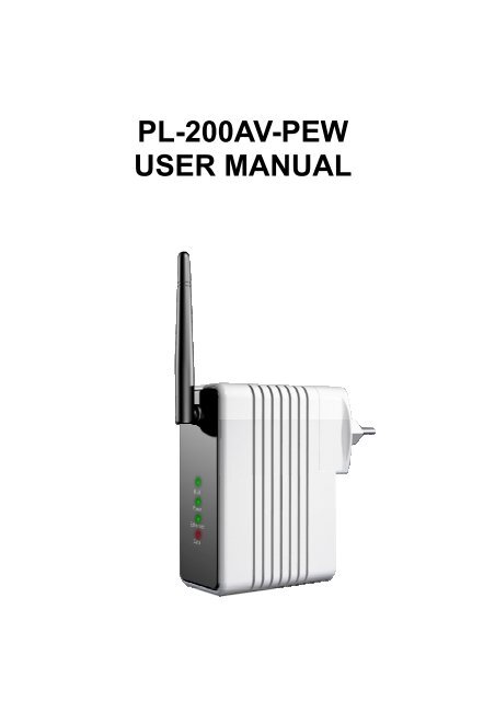
PL-200AV-PEW USER MANUAL - Solwise
PL-200AV-PEW USER MANUAL - Solwise
PL-200AV-PEW USER MANUAL - Solwise

Create successful ePaper yourself
Turn your PDF publications into a flip-book with our unique Google optimized e-Paper software.
<strong>PL</strong>-<strong>200AV</strong>-<strong>PEW</strong><br />
<strong>USER</strong> <strong>MANUAL</strong>
Contents<br />
1 Introduction .............................................................................................................. 1<br />
1.1 Features ...................................................................................................... 1<br />
1.2 System Requirements ................................................................................. 1<br />
1.3 Package Contents ....................................................................................... 2<br />
2 Safety Notice............................................................................................................ 3<br />
3 About the Adapter..................................................................................................... 4<br />
3.1 The Ethernet Interface................................................................................. 4<br />
3.2 The Adapter's Buttons ................................................................................. 4<br />
3.3 The Adapter's LEDs..................................................................................... 5<br />
3.4 Connecting the <strong>PL</strong>-<strong>200AV</strong>-<strong>PEW</strong> .................................................................. 6<br />
4 Wi-Fi Web configuration........................................................................................... 7<br />
4.1 Setting TCP/IP Properties............................................................................ 7<br />
4.2 Login............................................................................................................ 7<br />
4.3 Overview...................................................................................................... 8<br />
4.4 LAN.............................................................................................................. 9<br />
4.5 Wireless..................................................................................................... 10<br />
4.6 Security...................................................................................................... 11<br />
4.7 Management.............................................................................................. 13<br />
5 Installing <strong>PL</strong>C Utility Software ................................................................................ 14<br />
6 How to Use the Utility Software.............................................................................. 16<br />
6.1 Main Page ................................................................................................. 16<br />
6.2 Privacy page .............................................................................................. 19<br />
6.3 Diagnostics page ....................................................................................... 21<br />
6.4 About page................................................................................................. 23<br />
7 How to Use the SECURITY Pushbutton ................................................................ 24<br />
7.1 Creating a HomePlug AV Logical Network ................................................ 24<br />
7.2 Joining a Network ...................................................................................... 25<br />
7.3 Leaving a Network..................................................................................... 26<br />
Appendix A Specifications......................................................................................... 28<br />
Appendix B Acronyms and Abbreviations................................................................. 30<br />
Appendix C About <strong>PL</strong>C QoS..................................................................................... 31
<strong>PL</strong>-<strong>200AV</strong>-<strong>PEW</strong> <strong>USER</strong> <strong>MANUAL</strong><br />
1 Introduction<br />
This <strong>PL</strong>-<strong>200AV</strong>-<strong>PEW</strong> wallmount Wireless extender for transmitting data up to 200<br />
Mbps across the household power line and every power socket becomes a WLAN<br />
access point. Through the combination of these two technologies, you can wirelessly<br />
surf on line conveniently in the complicated corner that is used to be unreachable with<br />
wiring and data rate is up to 54 Mbps. It is suitable for using in a wide range of both<br />
residential (in-home) and commercial (offices, apartments, hotels, warehouses)<br />
network applications. No cables, no drilling. These adapters enable the effortless<br />
creation of a high-speed network that supports video, voice and data.<br />
1.1 Features<br />
Wallmount type and power voltage range of 100 V to 240 V AC 50/60Hz<br />
Compatible with IEEE 802.11b/g and HomePlug AV<br />
Support QAM 256/64/16/8, QPSK, BPSK, and ROBO modulation schemes<br />
Physical layer data rate up to 200 Mbps<br />
128-bit AES link encryption for <strong>PL</strong>C<br />
IEEE 802.11b/g<br />
Support WAP, WAP2, 64/128/152-bit WEP, SSID hide<br />
Wireless module supports AP and VAP mode<br />
Support GUI WEB interface<br />
1.2 System Requirements<br />
Operating System: Microsoft Windows 2000 or XP, Vista 32-bit<br />
CPU: Intel Pentium III or better, clock rate faster than 2.0GHz recommended<br />
RAM: At least 128MB<br />
Screen Resolution: Any resolution<br />
1
Free Disk Space: At least 20MB<br />
Network Interface: At least one fast Ethernet (100 Mbps) network card, and<br />
Ethernet cord<br />
1.3 Package Contents<br />
<strong>PL</strong>-<strong>200AV</strong>-<strong>PEW</strong> x 1<br />
CD ROM x 1<br />
RJ45 Ethernet cable x 1<br />
2
2 Safety Notice<br />
This device is intended for connection to the AC power line. For installation<br />
instructions, please refer to the installation section of this guide. The following<br />
precautions should be taken when using this product.<br />
Read all instructions before installing and operating this product.<br />
Follow all warnings and instructions marked on the product.<br />
Unplug the device from the wall outlet before cleaning. Use a damp cloth for<br />
cleaning. Do not use liquid cleaners or aerosol cleaners.<br />
Do not operate this product near water.<br />
This product should never be placed near or over a radiator or heat register.<br />
Do not use an extension cord between the device and the AC power source.<br />
Only a qualified technician should service this product. Opening or removing<br />
covers may result in exposure to dangerous voltage points or other risks.<br />
Unplug the device from the wall outlet and refer the product to qualified service<br />
personnel for the following conditions:<br />
- If liquid has been spilled into the product<br />
- If the product has been exposed to rain or water<br />
- If the product does not operate normally when the operating instructions are<br />
followed<br />
- If the product exhibits a distinct change in performance<br />
3
3 About the Adapter<br />
3.1 The Ethernet Interface<br />
Ethernet: The Ethernet port connects to an Ethernet network cable. The other end<br />
of the cable will connect to your computer or other Ethernet-enabled network<br />
device.<br />
3.2 The Adapter's Buttons<br />
Button<br />
Reset<br />
Security<br />
Description<br />
The Reset button is used to restore the factory defaults.<br />
The Security button is used to set the membership state.<br />
4
Note:<br />
Restoring the <strong>PL</strong>-<strong>200AV</strong>-<strong>PEW</strong> factory defaults will erase all of settings that you have<br />
set before, and replace them with the factory defaults. Please be careful for not<br />
retaining the reset button if you want to retain the former settings.<br />
3.3 The Adapter's LEDs<br />
All adapter's LEDs are located on the front panel, there are 3 LEDs to indicate the<br />
adapter’s status.<br />
Indicator Status Description<br />
Power(Green/Red)<br />
<strong>PL</strong>C(Green/Red)<br />
LAN (Green)<br />
WLAN (Green)<br />
On<br />
Flash<br />
On<br />
Flash<br />
On<br />
Flash<br />
On<br />
Flash<br />
When the LED is green, it indicates that the device<br />
is ready for use.<br />
When the LED is orange, it indicates that the<br />
device is loading firmware.<br />
When the <strong>PL</strong>C indicator is green, it indicates that<br />
powerline link is detected<br />
When serving as a STATION, the LED is green<br />
and flashes to indicate powerline activity.<br />
When serving as a CCO, the LED is green and<br />
lights steadily ON, even in the presence of<br />
powerline activity.<br />
Ethernet link is detected<br />
It indicates that data over Ethernet is activated.<br />
WLAN link is detected.<br />
It indicates that data over Wi-Fi link is activated.<br />
5
3.4 Connecting the <strong>PL</strong>-<strong>200AV</strong>-<strong>PEW</strong><br />
Step 1<br />
Step 2<br />
Put the <strong>PL</strong>-<strong>200AV</strong>-<strong>PEW</strong> to the AC power socket directly.<br />
Use one end of Ethernet network cable to connect to the<br />
<strong>PL</strong>-<strong>200AV</strong>-<strong>PEW</strong> Ethernet port, and another end connect to your PC<br />
Ethernet port.<br />
6
4 Wi-Fi Web configuration<br />
This chapter mainly describes how to configure the Access Point through Web page.<br />
4.1 Setting TCP/IP Properties<br />
The default IP address of <strong>PL</strong>-<strong>200AV</strong>-<strong>PEW</strong> is 192.168.1.1, you should set your PC’s IP<br />
address in the same subnet.<br />
4.2 Login<br />
Open IE and enter http://192.168.1.1 at the URL column to log in to <strong>PL</strong>-<strong>200AV</strong>-<strong>PEW</strong><br />
web page.<br />
7
In the login page, enter the user name and password.<br />
The default user name is admin.<br />
The default password is password.<br />
Click OK to log in to the web page, otherwise click Cancel to exit.<br />
4.3 Overview<br />
After finish login, the default page Overview appears. The Overview page displays<br />
the current status information, including version, LAN interface, wireless LAN and<br />
statistic information.<br />
8
Firmware Version: The current firmware version of Wi-Fi module.<br />
LAN MAC Address: The physics address of Ethernet interface.<br />
LAN IP/Subnet Mask: The IP address and the subnet mask of Ethernet interface.<br />
DHCP Server: It shows whether the DHCP server function is enabled or not.<br />
Channel: It shows the current channel of the wireless network settings.<br />
WLAN MAC Address: The physics address of Wi-Fi interface.<br />
This field shows the packets statistic information of Wi-Fi module<br />
Click Update to refresh the statistic information.<br />
4.4 LAN<br />
Click LAN and the following page appears. This page allows you to configure the LAN<br />
interface.<br />
IP Address: If necessary, you may set a fixed private IP address for Ethernet<br />
interface.<br />
Subnet Mask: According to the net segment to set the subnet mask.<br />
DHCP server automatically assigns an IP address to each computer on LAN,<br />
9
unless it already has one. It is highly recommended you enable the device as a<br />
DHCP server.<br />
When Disable is selected, the function of DHCP server is shut off. When Enable is<br />
selected, the function of DHCP server is activated and the following items appear.<br />
Lease Time: The life time of assigned IP that the DHCP server leases to.<br />
IP address Pool: The IP address range that DHCP Server leases to.<br />
After finishing the settings above, click Apply, and then the new settings take effect.<br />
The Wi-Fi module saves all changes to Flash.<br />
Click Cancel to discard all changes.<br />
4.5 Wireless<br />
Click Wireless and the following page appears. This page allows you to configure the<br />
wireless LAN interface.<br />
Mode: It consists three types of modes, including 802.11b, 802.11b/g Compatible<br />
and 802.11g Only. You may select the proper network mode. It is highly<br />
recommended that you select 802.11b/g Compatible.<br />
10
SSID (Service Set Identifier): The wireless network name shared among all the<br />
devices is case-sensitive and must not exceed 32 alphanumeric characters which<br />
may be any keyboard character. Make sure this setting is the same for all devices in<br />
the wireless network.<br />
Channel: Select the proper channel in the drop-down list. All devices in the wireless<br />
network must use the same channel in order to run correctly.<br />
Beacon Interval: If the value of beacon interval is small, it can accelerate the link<br />
speed. If the value is big, it can help to save power. The interval time range is<br />
between 25 and 500. The default value is 100.<br />
Data Rate: It is the wireless physics rate. It is highly recommended that you select<br />
Auto. If you select Auto, the data rate will automatically negotiate with other<br />
devices according to the situation. For a fixed data rate, you should set the proper<br />
data rate according to the Wi-Fi mode (such as 802.11b or 802.11g).<br />
After finishing the settings above, click Apply, and then the new settings take effect.<br />
The Wi-Fi module saves all changes to Flash.<br />
Click Cancel to discard all changes.<br />
4.6 Security<br />
Click Security and the following page appears. This page allows you to configure<br />
security for the wireless LAN interface.<br />
11
Encrypt: Select Enable to enable VAP security configuration or select Disable to<br />
disable it.<br />
Authentication Type: There are five types of authentication types, including Open<br />
System, Shared Key, Open & Shared, WPA-PSK, and WPA2-PSK.The default<br />
value is Open System, and also Shared Key can be used. For Open System, the<br />
sender and the recipient do not use a WEP key for authentication. For Shared Key<br />
authentication, the sender and recipient use a WEP key for authentication. In most<br />
cases, please keep the default value.<br />
If you select Open System, Shared Key, or Open & Shared mode, you may<br />
configure VAP WEP.<br />
WEP Key1-4: WEP keys are used to create an encryption scheme for wireless<br />
network transmissions. When not using a Passphrase, you can manually enter a<br />
set of values, and do not leave a key field blank. If you are using 64-bit WEP<br />
encryption, the key must be exactly 10 hexadecimal characters in length. If you are<br />
using 128-bit WEP encryption, the key must be exactly 26 hexadecimal characters<br />
12
in length. Valid hexadecimal characters are “0”-“9” and “A”-“F”.<br />
4.7 Management<br />
Click Management and the following page appears. This page allows you to upgrade<br />
the firmware.<br />
Fireware Upgrade:Current Firmware Version: This field shows the current<br />
firmware version.<br />
Locate New Firmware: Click Browse to select the new firmware in your PC. Click<br />
Upgrade to download the new firmware to the device.<br />
Restore Factory Defaults: Click the Restore button, then the all current<br />
configuration returns to factory default.<br />
Click the Save button, the all configuration will be stored into Flash.<br />
New Password: Set a new password for logging in to the Wi-Fi web.<br />
Confirm Password: Enter the new password again.<br />
After finishing the settings above, click Apply, and then the new settings take effect.<br />
The Wi-Fi module saves all changes to Flash.<br />
Click Cancel to discard all changes.<br />
13
5 Installing <strong>PL</strong>C Utility Software<br />
Note:<br />
Before installing the <strong>PL</strong>C utility software, make sure that there is no any other<br />
Powerline Utility installed on your computer. If there is another utility installed, please<br />
uninstall it and restart your computer.<br />
Please insert the utility CD-ROM into the computer’s CD-ROM drive. Double click the<br />
setup.exe, and then a page for installing the utility software appears.<br />
Click Next to show the following page.<br />
14
Click Browse to select the installation folder, and then click Next to continue.<br />
Click Close to finish the installation.<br />
15
6 How to Use the Utility Software<br />
6.1 Main Page<br />
The Main page provides a list of all powerline devices logically connected to the<br />
computer when the utility is running.<br />
The Device Type shows local HomePlug devices connected to the computer’s NIC<br />
(Network Interface Card). User can click the Connect button to make NIC connect to<br />
the local devices. Once connected to the local device, the utility will automatically<br />
scan the power line periodically for any other HomePlug devices. If no local<br />
HomePlug devices are discovered, the status area above the Connect button will<br />
show a message “NO HOME<strong>PL</strong>UG ADAPTERS DETECTED”.<br />
This page also displays all the HomePlug remote devices discovered on the current<br />
logical network. The total number of remote devices connected on the same network<br />
can be found above the Device Name. The Network type (Public or Private) is also<br />
16
displayed based on the network status of the local device. The scan status option is<br />
displayed on the top right corner above the MAC Address. The following information<br />
for all devices is displayed in the page.<br />
Device Name<br />
This field shows the default device name. User may modify the name by either using<br />
the Rename button or by clicking on the name to edit it.<br />
MAC Address<br />
This field shows the remote device’s MAC address.<br />
Password<br />
By default, this field is blank. Click Enter Password button, user may modify the<br />
password.<br />
To set the Password of the device (It is necessary when creating a private network),<br />
first select the device by clicking on its name and then click the Enter Password<br />
button. Set Device Password dialog box appears for setting the password. Enter<br />
your password in the password field. The password can be in any case formats, with<br />
or without dashed between them. Click OK to confirm the password.<br />
A confirmation box will appear if the password was entered correctly. If a device was<br />
not found, system will pop up the prompt for trouble shooting. This process may take<br />
a few seconds to get completed.<br />
17
Add<br />
This button is used to add a remote device to the existing network by entering the<br />
device password of the device. A Add Device to Network dialog box appears. You<br />
are allowed to set the device name and the password.<br />
A confirmation box will appear if the password was entered correctly and if the device<br />
was found in the powerline network. If a device was not found, system will pop up the<br />
prompt for trouble shooting.<br />
18
Note:<br />
The device must be present on the power line (plugged in) in order for the password<br />
to be confirmed and added to the network. If the device could not be located, a<br />
warning message will be shown.<br />
Scan<br />
This button is used to search the HomePlug devices connected to the Powerline<br />
network. By default, the utility automatically scans every few seconds and updates<br />
the information.<br />
6.2 Privacy page<br />
The Privacy page allows you to create a private network to keep the security of<br />
logical network.<br />
All HomePlug devices are using a default logical network (network name), usually<br />
19
“HomePlug”. The Privacy page allows user to change to a private network by<br />
modifying the network name (network password) of devices.<br />
The user can always reset to the HomePlug network (Public) by entering “HomePlug”<br />
as the network name or by clicking on the Use Default (Public Network) button.<br />
Note:<br />
Changing the network name to anything other than HomePlug, the main page will<br />
show the network type as Private.<br />
Set Local Device Only<br />
This button can be used to change the network name (network password) of the local<br />
device. If a new network password is entered, all the devices displayed on the<br />
previous main page will be no longer existed in the new network. Therefore, the local<br />
20
device can not communicate with the devices in the previous logical network. Devices<br />
previously set with the same logical network (same network name) will appear in the<br />
device list after selecting this option.<br />
Set All Devices<br />
This button is used to change the logical network of all devices that appear on the<br />
main page whose Device’s Password had been entered in the same logical network.<br />
After finishing modifying, a dialog box appears to remind you that the operation is<br />
successful. If the device password is not entered, it reminds you that the operation is<br />
failed.<br />
6.3 Diagnostics page<br />
The Diagnostics page shows the information about system and the history of all<br />
remote devices over a period of time.<br />
The System Information shows software and hardware technical specifications of<br />
21
the host computer on the Powerline network. It includes the following information.<br />
• Operating system platform or version<br />
• Host Network Name<br />
• User Name<br />
• MAC Address of all NICs (Network interface card) connected to the host<br />
• Versions of all Driver DLLs and libraries used (NDIS) (optional)<br />
• HomePlug chipset manufacturer name (Turbo Only devices)<br />
• MAC firmware version (Turbo Only devices)<br />
• MAC addresses of all devices connected locally to the host<br />
• Version of the configuration utility<br />
• Vendor name<br />
The Lower panel contains the history information of all remote devices displayed on<br />
the computer over a certain period of time. All devices that were on the powerline<br />
network are listed here along with a few other parameters. Devices that are active on<br />
the current logical network will show a transfer rate in the Rate field. For the devices<br />
on the other networks, or devices that may no longer exist, “?” symbols are shown in<br />
the corresponding Rate fields. Remote Divice History displays the following<br />
information.<br />
• Device alias name<br />
• Device MAC address<br />
• Device password<br />
• Up-to-the-minute rate<br />
• Up-to-the-minute network name<br />
• HomePlug chipset manufacturer name<br />
• Up-to-the-minute date and time<br />
• MAC firmware version<br />
The diagnostics information displayed may be saved as a text file for backup, or can<br />
be printed for reference as technical support. For the devices that are not part of the<br />
22
network anymore, can be deleted by using the delete button. A dialog box pops up<br />
with a confirmation message if we try to delete a device whose password has been<br />
entered.<br />
6.4 About page<br />
The About screen shows the software version and provides a HTML link to the<br />
manufactory website.<br />
Preferences<br />
You may select enable or disable auto-scan feature.<br />
23
7 How to Use the SECURITY Pushbutton<br />
This section describes how to add new devices to, or remove old devices from a<br />
HomePlug AV logical network(AVLN)by using a SECURITY pushbutton.<br />
The operation progress and outcome can be monitored by observing the status of the<br />
Power LED.<br />
7.1 Creating a HomePlug AV Logical Network<br />
If you want to create a logical network through two devices with different SECURITY<br />
values and the two devices are connected to the same powerline, you can follow the<br />
steps below.<br />
Step 1 Press the SECURITY button on the first device A for less than 3 seconds.<br />
Step 2 Press the SECURITY button on the second device B for less than 3<br />
seconds. The button on device B must be pressed within 1 minute.<br />
Step 3 Wait for the connection between A and B to complete.<br />
The Power LED on both devices will flash evenly at 1-second intervals until the<br />
operation succeeds or fails. If the operation succeeds, the power LED will illuminate<br />
steadily. If an error occurs, the power LED on the ‘adder’ will flash unevenly until the<br />
pushbutton on the ‘adder’ is pressed again or the ‘joiner’ is reset by holding the<br />
pushbuttons down for more than 10 seconds.<br />
24
A<br />
<strong>PL</strong>C<br />
B<br />
<strong>PL</strong>C<br />
C<br />
<strong>PL</strong>C<br />
A and B are not part of AVLN<br />
A and B want to form an AVLN<br />
Press NMK button on A less than 3 sec.<br />
Press NMK button on B less than 3 sec.<br />
A becomes “joiner”<br />
B becomes “joiner”<br />
B determines that A MAC address < B MAC address<br />
B becomes “adder”<br />
A accepts NMK from B<br />
7.2 Joining a Network<br />
In this scenario a network exists, a new device, the ‘joiner’, wants to join the network.<br />
Any device on the existing network can become the ‘adder’.<br />
Step 1<br />
Step 2<br />
Step 3<br />
Press the pushbutton on the ‘joiner’ for at least 3 seconds.<br />
Press the pushbutton on any network device for less than 3 seconds,<br />
making it the ‘adder’. Please press this pushbutton within 1 minute.<br />
Wait for connection to complete.<br />
The Power LED on both devices will flash at 1-second intervals until the process<br />
succeeds or fails. It will illuminate steadily on success. If an error occurs, the Power<br />
LED on the ‘adder’ will flash unevenly until the pushbutton on the ‘adder’ is pressed<br />
again or the ‘joiner’ is reset by pressing the pushbutton for more than 10 seconds.<br />
25
A<br />
<strong>PL</strong>C<br />
B<br />
<strong>PL</strong>C<br />
C<br />
<strong>PL</strong>C<br />
A and B form an AVLN<br />
C wants to join the AVLN<br />
Press NMK button on B less than 3 sec.<br />
Press NMK button on C less than 3 sec.<br />
B becomes “adder”<br />
C becomes “joiner”<br />
C accepts NMK from B<br />
7.3 Leaving a Network<br />
A network exists. The user wants to remove one device, the ‘leaver’, from that<br />
network, for whatever reason. He may want to remove the device from service<br />
altogether or have it join another logical network.<br />
Step 1 Press the pushbutton on the ‘leaver’ for at least 10 seconds. The device<br />
will reset and restart with a random SECURITY.<br />
Step 2 Wait for reset to complete.<br />
The Power LED on the ‘leaver’ will momentarily extinguish during reset, flash during<br />
restart then illuminate steadily. No errors can occur.<br />
Once the process completes, the user may disconnect the device from the medium or<br />
join it to another logical network on the same medium.<br />
26
A<br />
<strong>PL</strong>C<br />
B<br />
<strong>PL</strong>C<br />
C<br />
<strong>PL</strong>C<br />
A, B and C form an AVLN<br />
A wants to leave the AVLN<br />
Press NMK button on A more than 10 sec.<br />
A computes random NMK<br />
C resets and restarts<br />
27
Appendix A Specifications<br />
<strong>PL</strong>C Module SPEC<br />
<strong>PL</strong>C Chipset<br />
Intellon INT6400/INT1400<br />
Serial Flash<br />
16MB<br />
SDRAM:<br />
128MB<br />
Firmware<br />
Support North America/Europe/APAC/Japan<br />
Protocol HomePlug AV, coexists with existing HomePlug 1.0<br />
<strong>PL</strong>C Rate<br />
200Mbps<br />
Data Rate<br />
65Mbps TCP<br />
90Mbps UDP<br />
Modulation Band 2 MHz~30MHz<br />
Modulation Schemes Support 1024/256/64/16/8-QAM, QPSK,BPSK and ROBO<br />
Encryption<br />
128-bit AES<br />
QoS<br />
Support contention-free access, four-level priority based<br />
contention access, and multi segment bursting<br />
Support VLAN Priority<br />
Support ToS and CoS Packet Classifier<br />
Work Mode<br />
TDMA and priority based CSMA/CA<br />
Multicast Support Supports IGMP managed multicast sessions<br />
Wi-Fi Module SPEC<br />
Wireless Chipset Atheros AR2317<br />
Protocol<br />
IEEE 802.11b/g<br />
Wireless Rates For 802.11b: 11 Mbps, 5.5 Mbps, 2 Mbps, and 1Mbps<br />
For 802.11g: 54 Mbps, 48 Mbps, 36 Mbps, 24 Mbps, 18<br />
Mbps, 12 Mbps, 9 Mbps and 6Mbps<br />
Security<br />
WPA, WPA2, 64/128/152-bit WEP, Hide SSID<br />
28
MAC Address Access Control List<br />
Frequency Range 2.4GHz~2.4835GHz<br />
Work Mode<br />
Access Point<br />
System SPEC<br />
System Support Windows 98SE, 2000, ME, XP 32/64 bit and Vista 32/64bit<br />
LED’s<br />
Power: The power LED lights up when the adapter is<br />
powered on.<br />
<strong>PL</strong>C: <strong>PL</strong>C link and activity<br />
LAN: Ethernet link and activity<br />
WLAN: Wireless link and activity<br />
Push Button<br />
Reset: Reset system or restore the factory defaults.<br />
Security: Used to set the membership state.<br />
Ethernet Interface 1 x RJ45 for 10/100 Ethernet (Auto MDI/MDI-X)<br />
Consumption<br />
5.5W (Max)<br />
Environment Requirement<br />
Operating Temperature 0ºC~40ºC<br />
Storage Temperature -20ºC~70ºC<br />
Operating Humidity 10%~85%, non-condensing<br />
Storage Humidity 5%~90%, non-condensing<br />
Input Rating<br />
100V-240 V AC, 50/60Hz<br />
EMC and Safety<br />
Regulatory<br />
Compliance<br />
FCC Part 15 Class B<br />
CE<br />
Safety Regulations UL<br />
Green Standard RoHS<br />
Physical Characteristics<br />
Dimension<br />
L×W×H: 117mm×75mm×47mm<br />
Weight<br />
216g<br />
29
Appendix B Acronyms and Abbreviations<br />
AVLN<br />
CCo<br />
CSMA/CA<br />
DAK<br />
IGMP<br />
NEK<br />
NID<br />
SECURITY<br />
<strong>PL</strong>C<br />
PIB<br />
STA<br />
TDMA<br />
TEI<br />
TOS<br />
VLAN<br />
AV In-home Logical Network, the AVLAN is the set of<br />
STAs that possess the same network Membership key,<br />
every AVLN is managed by a single CCo<br />
Central Coordinator, the CCo is a superset of a STA<br />
which provisioning of terminal equipment identifiers and<br />
global link identifiers<br />
Carrier Sense Multiple Access / Collision Avoidance<br />
Device Access Key<br />
Internet Group Management Protocol<br />
Network Encryption Key<br />
Network ID (Identification)<br />
Network Membership Key<br />
Power Line Communication<br />
Parameter Information Block<br />
Station, a STA in the network with a connection to the<br />
power line and being able to source or sink traffic<br />
Time Division Multiple Access<br />
Terminal Equipment Identifier<br />
Type Of Service<br />
Virtual Local Area Network<br />
30
Appendix C About <strong>PL</strong>C QoS<br />
<strong>PL</strong>-<strong>200AV</strong>-<strong>PEW</strong> allows 4 levels of Channel Access Priority CAP (0~3). The 8 levels of<br />
VLAN Ethernet tags must be mapped to the 4 levels of CAP priority, where CAP 3 is<br />
the highest priority and CAP 0 is the lowest. CAP 3 priority might be used for voice<br />
and network management frames. CAP 2 is used for streaming video and music<br />
while CAP 1 and CAP 0 are used for data.<br />
Default CAP<br />
The ‘Default CAP’ group allows for default priority mapping of packets that do not<br />
have a VLAN TAG. Settings are available for Unicast (directed to a host).<br />
IGMP - (default CAP 3) - sets the channel access priority for IGMP frames - these<br />
are the group management frames, not the stream data.<br />
Unicast - (default CAP 1) - sets the default channel access priority for unicast<br />
frames not matching any other classification or mapping.<br />
IGMP managed Multicast Stream (Fixed to CAP 2) - sets the default channel<br />
access priority for stream data belonging to a snooped IGMP multicast group.<br />
Multicast/Broadcast - sets the default CAP for multicast frames not in a snooped<br />
group and for broadcast frames.<br />
The following are the factory default settings for VLAN Tags and TOS Bits:<br />
VLAN Tag<br />
Default CAP<br />
TOS Bit User<br />
Default CAP<br />
User riority<br />
Priority<br />
Priority<br />
Priority<br />
0 CAP1 0 CAP1<br />
1 CAP0 1 CAP0<br />
2 CAP0 2 CAP0<br />
3 CAP1 3 CAP1<br />
31
4 CAP2 4 CAP2<br />
5 CAP2 5 CAP2<br />
6 CAP3 6 CAP3<br />
7 CAP3 7 CAP3<br />
32