Bus Controls - ASCO Valve Net
Bus Controls - ASCO Valve Net
Bus Controls - ASCO Valve Net

Create successful ePaper yourself
Turn your PDF publications into a flip-book with our unique Google optimized e-Paper software.
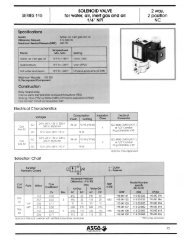
<strong>Bus</strong> <strong>Controls</strong><br />
Automation Operator Specifications<br />
All of the operators listed below are intended for use on clean, dry air or inert gas filtered to 50 micrometers or better.<br />
To prevent freezing, the dew point of the media should be at least 18˚F (-8˚C) below the minimum temperature to which<br />
any portion of the clean air or gas system could be exposed. Instrument air, in compliance with ANSI/ISA Standard<br />
S7.3-1975 (R1981), exceeds the above requirements and is, therefore, an acceptable medium for these valves.<br />
Intrinsically Safe Piezo<br />
Cover<br />
Adapter<br />
Guide<br />
Piston<br />
Stem<br />
Manual Operator Gasket<br />
O-Ring & U-Cup Seals<br />
Operator Parts in Contact with Fluids<br />
Enclosure Type: NEMA 4, 4X<br />
Input Voltage: 6-30VDC<br />
Current Usage: 1.4 - 9.3 mA<br />
Power Consumption: 0.0084 - 0.24 watts<br />
Response Time: ≤ 350 ms<br />
Ambient Temperature: 32˚F to 140˚F<br />
Momentary Manual Operator standard.<br />
Approvals:<br />
FM - approved under J.I. 3W8A8AX<br />
CSA pending - file under LR - 13976-116C<br />
ATEX EEx ia IIC T6 @ 60˚ pending.<br />
Zenite (LCP)<br />
Ryton (PPS)<br />
Ryton (PPS)<br />
Delrin (CA)<br />
PC/PBT<br />
Santoprene<br />
NBR, FKM<br />
Zenite and Delrin are trademarks of Dupont.<br />
Ryton is a trademark of Philipps 66.<br />
Santoprene is a trademark of Advanced Elastomer Systems.<br />
Entity<br />
Parameters<br />
Groups A-D<br />
V max - 30 VDC<br />
I max - 100 mA<br />
Capacitance = 0<br />
Inductance = .264 mh<br />
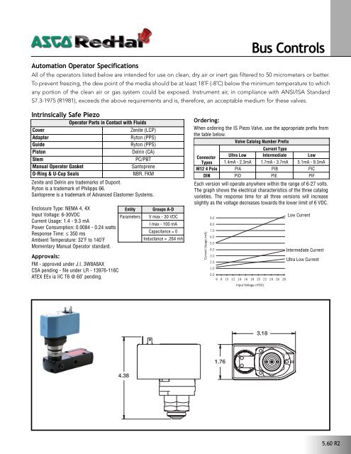
Ordering:<br />
When ordering the IS Piezo <strong>Valve</strong>, use the appropriate prefix from<br />
the table below.<br />
<strong>Valve</strong> Catalog Number Prefix<br />
Current Type<br />
Connector<br />
Ultra Low Intermediate Low<br />
Types 1.4mA - 2.3mA 1.7mA - 3.7mA 5.1mA - 9.3mA<br />
M12 4 Pole PIA PIB PIC<br />
DIN PID PIE PIF<br />
Each version will operate anywhere within the range of 6-27 volts.<br />
The graph shows the electrical characteristics of the three catalog<br />
varieties. The response time for all three versions will increase<br />
slightly as the voltage decreases towards the lower limit of 6 VDC.<br />
Current Usage (mA)<br />
9.0<br />
8.0<br />
7.0<br />
6.0<br />
5.0<br />
4.0<br />
3.0<br />
2.0<br />
1.0<br />
0.0<br />
6 8 10 12 14 16 18 20 22 24 26 28<br />
Input Voltage (VDC)<br />
Low Current<br />
Intermediate Current<br />
Ultra Low Current<br />
3.18<br />
1.76<br />
4.38<br />
5.60 R2
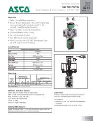
<strong>Bus</strong> <strong>Controls</strong><br />
Automation Operator Specifications<br />
All of the operators listed below are intended for use on clean, dry air or inert gas filtered to 50 micrometers or better.<br />
To prevent freezing, the dew point of the media should be at least 18˚F (-8˚C) below the minimum temperature to which<br />
any portion of the clean air or gas system could be exposed. Instrument air, in compliance with ANSI/ISA Standard<br />
S7.3-1975 (R1981), exceeds the above requirements and is, therefore, an acceptable medium for these valves.<br />
<br />
Specifications:<br />
Enclosure Type: NEMA 4, 4X Vendor ID: 11 (0B hex)<br />
Operating Voltage: 11-24 VDC<br />
Operating Current: 100 mA<br />
<strong>Bus</strong> Address: 0 to 63 (63-default address from factory).<br />
Addressing Software settable by using handheld device or<br />
configuration software.<br />
Topology: Trunk/dropline with branching<br />
Ambient Temperature: 14˚F to 140˚F<br />
Connection: 5-pin mini type (standard) or M12 multipin (optional).<br />
EDS File: Contact <strong>ASCO</strong>.<br />
Baud Rates 125 Kbps 250 Kbps 500 Kbps<br />
Thick (Type II) cable 500 m (1640 ft) 250 m (820 ft) 100 m (328 ft)<br />
Thin (Type I) cable 100 m (328 ft) 100 m (328 ft) 100 m (328 ft)<br />
Flat (Type III) cable 380 m (1250 ft) 200 m (656 ft) 75 m (246 ft)<br />
Maximum drop Length 6 m (20 ft) 6 m (20 ft) 6 m (20 ft)<br />
Cumulative drop length 156 m (512 ft) 78 m (328 ft) 39 m (128 ft)<br />
Thick cable = Four #16 AWG cable + one #22 AWG drain cable;<br />
used as trunk cable.<br />
Thin cable = Four #22 AWG cable + one #22 AWG drain cable;<br />
used as drop cable.<br />
Flat cable = Four #16 AWG cable, no drain cable; used as trunk cable.<br />
Approvals:<br />
Device<strong>Net</strong> certification version A13.<br />
Ordering:<br />
When ordering the Device<strong>Net</strong> Operator, add prefix WBDN for 5-pin<br />
mini type connection or WBDM for M12 multipin connection.<br />
1.96<br />
[50]<br />
SCREW, COVER<br />
COVER<br />
GASKET, COVER SCREW<br />
GASKET, COVER<br />
1.88<br />
[48]<br />
2.68<br />
[68]<br />
COIL ASSY.<br />
CONNECTOR<br />
276913-001<br />
4.70<br />
[119]<br />
COIL MARKING IN THIS AREA<br />
5.61 R2
<strong>Bus</strong> <strong>Controls</strong><br />
Automation Operator Specifications<br />
All of the operators listed below are intended for use on clean, dry air or inert gas filtered to 50 micrometers or better.<br />
To prevent freezing, the dew point of the media should be at least 18˚F (-8˚C) below the minimum temperature to which<br />
any portion of the clean air or gas system could be exposed. Instrument air, in compliance with ANSI/ISA Standard<br />
S7.3-1975 (R1981), exceeds the above requirements and is, therefore, an acceptable medium for these valves.<br />
Specifications:<br />
Enclosure Type: NEMA 4, 4X<br />
Operating Current: 14.3 mA<br />
Operating Voltage: 12.5VDC for IS applications and 24 VDC for<br />
non-IS applications.<br />
<strong>Bus</strong> Address: 0 to 125 (126-default address from factory).<br />
Topology: <strong>Bus</strong>, line, star and combinations.<br />
Supported Baud Rate: 31.25 Kbps<br />
Operator Response Time: 350 msec<br />
Ambient Temperature: 32˚F to 140˚F<br />
Connection: (2) M12 multipin; (1) male for network connection;<br />
(1) female for connecting up to 2 NAMUR proximity sensors.<br />
Momentary Manual Operator standard.<br />
GSD File (General Service Description): Contact <strong>ASCO</strong>.<br />
DD File (Device Description): Contact <strong>ASCO</strong>.<br />
Application Area Supply Voltage<br />
Maximum<br />
Supply Current<br />
Typical Number<br />
of Devices<br />
EEx ia/ib IIC 12.5 VDC 100 mA 8<br />
EEx ib IIC 12.5 VDC 110 mA 8<br />
Not intrinsically safe 24 VDC 400 mA 32<br />
*This table is based on a minimum current consumption of 14.3 mA per<br />
device. If a device consumes more than 14.3 mA, the number of devices<br />
that can be connected is reduced. The maximum distance corresponds<br />
to a fully loaded Profibus-PA segment.<br />
Approvals:<br />
Profibus Trade Organization (PTO): PROFIBUS-PA slave.<br />
Device Certification FM: Intrinsically safety.<br />
Ordering:<br />
When ordering the Profibus Operator, add prefix PR.<br />
5.62 R2
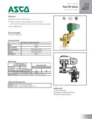
<strong>Bus</strong> <strong>Controls</strong><br />
Specifications<br />
Pipe<br />
Size<br />
(ins.)<br />
Exh.<br />
Pipe<br />
Size<br />
(ins.)<br />
Orifice<br />
Dia.<br />
(ins.)<br />
Exh.<br />
Orifice<br />
Dia.<br />
(ins.)<br />
Cv<br />
Flow<br />
Press.<br />
Cv<br />
Flow<br />
Exh.<br />
Operating Pressure<br />
Differential (psi)<br />
Max. DC<br />
Air-Inert<br />
Gas<br />
Max.<br />
Fluid<br />
Temp.˚F<br />
Const.<br />
Ref.<br />
Const.<br />
Ref.<br />
Approx.<br />
Shipping<br />
Weight<br />
(lbs.) ➂<br />
Min.<br />
Brass ➁<br />
Stainless Steel ➁<br />
3/2 Normally Closed<br />
1/4 1/4 1/16 1/16 .08 .08 0 150 140 8314A300 1 8314A301 2 1.6<br />
1/4 1/8 1/16 1/4 .08 .73 5 150 140 8317A307 7 8317A308 7 1.7<br />
1/4 1/4 5/16 5/16 1.5 1.5 1 150 140 8316A301 3 8316A381V 3 3.5<br />
3/8 3/8 5/16 5/16 1.8 1.8 1 150 140 8316A302 3 8316A382V 3 3.5<br />
3/8 3/8 5/8 5/8 4.0 4.0 1 150 140 8316A303 4 - - 4.0<br />
1/2 1/2 5/8 5/8 4.0 4.0 1 150 140 8316A304 4 8316A384V 4 4.1<br />
3/4 3/4 11/16 11/16 5.5 5.5 10 150 140 8316A374 5 - - 4.7<br />
1 1 1 1 13.0 13.0 10 150 140 8316A334 6 - - 8.5<br />
4/2 Single Solenoid<br />
1/4 3/8 1/4 1/4 0.8 1.0 10 150 140 8344A370 9 - - 5.2<br />
3/8 1/2 3/8 3/8 1.4 2.2 10 150 140 8344A372 10 - - 9.6<br />
1/2 1/2 3/8 3/8 1.4 2.2 10 150 140 8344A374 10 - - 9.6<br />
3/4 1 3/4 3/4 5.2 5.6 10 150 140 8344A376 11 - - 18.6<br />
1 1 3/4 3/4 5.2 5.6 10 150 140 8344A378 11 - - 18.6<br />
4/2 Dual Solenoid<br />
1/4 3/8 1/4 1/4 0.8 1.0 10 150 140 8344A344 12 - - 5.2<br />
3/8 1/2 3/8 3/8 1.4 2.2 10 150 140 8344A380 13 - - 9.6<br />
1/2 1/2 3/8 3/8 1.4 2.2 10 150 140 8344A382 13 - - 9.6<br />
3/4 1 3/4 3/4 5.2 5.6 10 150 140 8344A354 14 - - 18.6<br />
1 1 3/4 3/4 5.2 5.6 10 150 140 8344A356 14 - - 18.6<br />
5/2 Single Solenoid<br />
1/4 1/4 1/16 1/16 .08 .08 10 150 140 8345A301 8 8345A381 8 3.8<br />
1/4 1/4 1/4 1/4 .84 .84 35 150 140 - - 8551A353 15 5.5<br />
5/2 Dual Solenoid<br />
1/4 1/4 1/4 1/4 .84 .84 35 150 140 - - 8551A388 17 5.5<br />
5/2 Direct Mount Single Solenoid<br />
1/4 1/4 1/4 1/4 .84 .84 35 150 140 - - 8551A355 16 6.5<br />
5/2 Direct Mount Dual Solenoid<br />
1/4 1/4 1/4 1/4 .84 .84 35 150 140 - - 8551A390 18 6.5<br />
1 Zero minimum when valve selection gasket is in external position and proper auxiliary air pressure is applied. See graph below for pilot line pressure<br />
versus mainline pressure. Minimum 15 psi operating pressure differential when selection gasket is in internal position.<br />
➁ These valves are not available without one of the prefixes from the <strong>Bus</strong> Control Section.<br />
➂ Weights are the valve body only. (Add .5 for Piezo, .9 for Device<strong>Net</strong>, or .6 for Profibus.)<br />
MAINLINE PRESSURE vs. PILOT LINE PRESSURE<br />
when selection gasket is in external position<br />
PILOT LINE PRESSURE (psi)<br />
120<br />
106<br />
90<br />
75<br />
60<br />
45<br />
30<br />
15<br />
0<br />
0 15 30 45 60 75 90 105 120 135 150<br />
MAINLINE PRESSURE (psi)<br />
For dimensional information on specific valve configurations<br />
see the relevant catalog page.<br />
5.63 R2
Capabilities Chart<br />
Base Catalog Number Resilient Materials Other Standard Rebuild Kit<br />
<strong>Bus</strong> <strong>Controls</strong><br />
Brass<br />
Stainless Steel<br />
NBR<br />
FKM<br />
EPDM<br />
Neoprene<br />
Oxygen Service<br />
PTFE<br />
Urethane<br />
Vacuum<br />
8314A300 8314A301 ● - - - - - - - MS - 322450 322450 322294 322294 322450 322450<br />
8316A301 - ● - - - - - - - MO MB 322487 - 316982 - 322487 -<br />
- 8316A381V - ●1 - - - - - - MO MB - 322451 - 316982-V - 322451<br />
8316A302 - ● - - - - - - - MO MB 322487 - 316982 - 322487 -<br />
- 8316A382V - ●1 - - - - - - MO MB - 322451 - 316982-V - 322451<br />
8316A303 - ● - - - - - - - MO MB 322488 - 316966 - 322488 -<br />
8316A304 - ● - - - - - - - MO MB 322488 - 316966 - 322488 -<br />
- 8316A384V - ●1 - - - - - - MO MB - 322805 - 318399-V - 322805<br />
8316A374 - ● - - - - - - - MO MB 323212 - 316847 - 323212 -<br />
8316A334 - ● - - - - - - - MO MB 323213 - 316850 - 323213 -<br />
8317A307 8317A308 ● - - - - - - - - - 322494 322494 322295 322295 322494 322494<br />
8345A301 8345A381 ● - - - - - - - MO - 322495 322495 316844 318802 322495 322495<br />
8344A370 - ● - - - - - - - MO - 322711 - 316841 - 322711 -<br />
8344A372 - ● - - - - - - - MO - 323214 - 316842 - 323214 -<br />
8344A374 - ● - - - - - - - MO - 323215 - 316842 - 323215 -<br />
8344A376 - ● - - - - - - - MO - 323216 - 316848 - 323216 -<br />
8344A378 - ● - - - - - - - MO - 323217 - 316848 - 323217 -<br />
8344A344 - ● - - - - - - - MO - 323218 - 316843 - 323218 -<br />
8344A380 - ● - - - - - - - MO - 323219 - 316846 - 323219 -<br />
8344A382 - ● - - - - - - - MO - 323220 - 316846 - 323220 -<br />
8344A354 - ● - - - - - - - MO - 323221 - 316851 - 323221 -<br />
8344A356 - ● - - - - - - - MO - 323222 - 316851 - 323222 -<br />
● = Standard. 1 Main valve resilient materials are in FKM. Operator resilient materials are in NBR.<br />
Manual Operator<br />
Mounting Bracket<br />
Intrinsically Safe<br />
Piezo Brass<br />
Intrinsically Safe<br />
Piezo Stainless Steel<br />
Device<strong>Net</strong> Brass<br />
Device<strong>Net</strong><br />
Stainless Steel<br />
Profibus Brass<br />
Profibus<br />
Stainless Steel<br />
5.64 R2