Create successful ePaper yourself
Turn your PDF publications into a flip-book with our unique Google optimized e-Paper software.
October 28, 2011<br />
Mr. David Lloyd<br />
<strong>Christie</strong> <strong>Lites</strong> Vancouver<br />
3686 Bainbridge Avenue<br />
Burnaby, BC V5A 2T4<br />
Civil Engineers<br />
Structural Engineers<br />
Project: 12" Type A <strong>Truss</strong> Analysis, Our File No. 211503.20<br />
Subject: <strong>Truss</strong> Span Rating<br />
Landscape Architects<br />
Dear David:<br />
On October 12, 2011, AHBL, Inc. was contracted by <strong>Christie</strong> <strong>Lites</strong> Inc to conduct a structural<br />
capacity investigation for the <strong>Christie</strong> <strong>Lites</strong> 12” Type A <strong>Truss</strong> System. The scope of our<br />
structural services included structural analysis of the complete truss assembly, including the<br />
12” <strong>Truss</strong> Corners and curved trusses, in order to develop span charts for the trusses. Our<br />
analysis was based on member sizes, truss configuration, and material properties that were<br />
provided to AHBL by <strong>Christie</strong> <strong>Lites</strong>.<br />
Community Planners<br />
Natural Resource Ecologists<br />
Land Surveyors<br />
Neighbors<br />
The basic 12” Type A truss configuration consists of an 8’-0” long, three dimensional, box<br />
shaped truss. Each truss section has four continuous horizontal chords, interconnected with<br />
both vertical and diagonal web members. The diagonal web members are located primarily in<br />
the vertical plane and span between top and bottom chords. Two additional diagonals are<br />
provided at 1/3 points and span across the body of the truss. Crossbeams are provided at 1/4<br />
points and span horizontally between chords. Variations of this basic 12” truss include shorter<br />
sections of 1’-0”, 2’-0”, 3’-0”, 4’-0”, and 6’-0” long and curved truss sections of approximately<br />
12’-0” and 18’-0” diameter.<br />
Corner blocks are available in 22.5-degree, 30-degree, 45-degree, 90-degree, and 6-way hub<br />
units. The corner units are used to join truss sections in horizontal layouts and to provide<br />
locations for support, either ground or aerial. The corner blocks are comprised of sections and<br />
materials identical to the trusses.<br />
The 12” Type A truss was modeled in RISA-3D in order to determine the elements of the<br />
trusses that controlled the truss capacity. A three dimensional model was built for 8’, 16’, 24’,<br />
32’, and 40’ spans (each truss span over 8’ involved bolting 8’ sections of truss in series), and<br />
analyzed under several loading conditions. The loading conditions included distributed loads,<br />
as well as point loads at midspan, third points or quarter points of the truss. For each of these<br />
models, the limiting truss element was reviewed, and a maximum allowable load determined<br />
based on this element. Depending on the truss span and type of loading, the factor that<br />
limited the allowable truss capacity included axial compression of the top chord, axial tension<br />
of the bottom chord, axial compression of the diagonal web members, as well as truss<br />
S E A T T L E<br />
1200 6th Avenue, Suite 1620<br />
Seattle, WA 98101-3117<br />
206.267.2425 TEL<br />
206.267.2429 FAX<br />
www.ahbl.com
Mr. David Lloyd<br />
October 28, 2011<br />
211503.20<br />
Page 2<br />
deflection. In addition to these, the truss-to-truss splice connection (using either a corner<br />
block or direct bolted connection) was determined to be the limiting element in many<br />
instances. This connection was limited by yielding of the aluminum connection plates at the<br />
locations of the 5/8”-diameter thru bolts. Based upon our analysis, the span charts that we<br />
developed are as follows:<br />
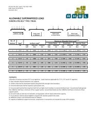
Load Chart One: Allowable loads for Typical Type A <strong>Truss</strong> sections in series
Mr. David Lloyd<br />
October 28, 2011<br />
211503.20<br />
Page 3<br />
Load Chart Two: Allowable loads for Type A Curved <strong>Truss</strong> – 12’-0-3/4” Diameter
Mr. David Lloyd<br />
October 28, 2011<br />
211503.20<br />
Page 4<br />
Load Chart Three: Allowable loads for Type A Curved <strong>Truss</strong> – 18’-0-3/4” Diameter
Mr. David Lloyd<br />
October 28, 2011<br />
211503.20<br />
Page 5<br />
Load Chart Four: Acceptable Uses of Corner Blocks
Mr. David Lloyd<br />
October 28, 2011<br />
211503.20<br />
Page 6<br />
Three dimensional drawings of the 12” Type A trusses and corner blocks were provided by<br />
<strong>Christie</strong> <strong>Lites</strong> for our analysis. In addition, detailed member information was provided to AHBL<br />
by <strong>Christie</strong> <strong>Lites</strong> for the purposes of building the computer model used for analysis. The<br />
approximate truss dimensions and member information is as follows:<br />
<strong>Truss</strong> Width: 1’-0” (outside to outside dimensions)<br />
<strong>Truss</strong> Depth: 1’-0” (outside to outside dimensions)<br />
<strong>Truss</strong> Span: 8’-0” for each truss unit<br />
<strong>Truss</strong> Material: 6061 T6 Aluminum unless noted otherwise<br />
<strong>Truss</strong> Top Chord: 2” diameter x 0.125”<br />
<strong>Truss</strong> Bottom Chord: 2” diameter x 0.125”<br />
<strong>Truss</strong> Diagonal Webs: 1” diameter x 0.125”<br />
<strong>Truss</strong> Vertical Webs (midspan): 1” diameter x 0.125”<br />
<strong>Truss</strong> Diagonal Cross Members: 1” diameter x 0.125”<br />
<strong>Truss</strong> Vertical Webs (endspan): 1” x 2” x 0.125” rectangular tubes<br />
<strong>Truss</strong> Horizontal Cross Members (endspan): 1” x 2” x 0.125” rectangular tubes<br />
<strong>Truss</strong> Horizontal Cross Members (midspan): 2” diameter x 0.125”<br />
End Connections Plates: 13/32”<br />
<strong>Truss</strong> Splice Bolts: 5/8” diameter grade 8 bolts<br />
This concludes our summary of the 12” Type A <strong>Truss</strong> analysis. RISA-3D truss models of the<br />
various span conditions may be made available on request. If you wish for us to be involved in<br />
additional review or design of the 12” Type A trusses, please let us know, and we will be glad<br />
to assist you. Otherwise, if you have any questions, or require further explanation, please feel<br />
free to call Tom Hicks, PE, SE, or me at (206) 267-2425.<br />
Sincerely,<br />
Andrea M. Sauter, PE, SE<br />
Project Engineer<br />
AMS/el<br />
c: Drew McEachern, AHBL<br />
Q:\2011\211503\WORDPROC\Letters\20111028_<strong>Truss</strong>_Span_<strong>Report</strong>_Ltr_211503.20.docx