Hardware Reference - Stollmann
Hardware Reference - Stollmann
Hardware Reference - Stollmann

Create successful ePaper yourself
Turn your PDF publications into a flip-book with our unique Google optimized e-Paper software.
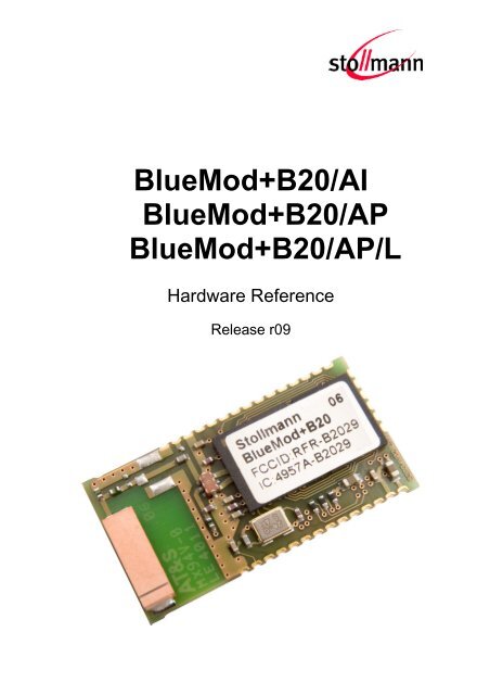
BlueMod+B20/AI<br />
BlueMod+B20/AP<br />
BlueMod+B20/AP/L<br />
<strong>Hardware</strong> <strong>Reference</strong><br />
Release r09
BlueMod+B20/AI<br />
BlueMod+B20/AP<br />
BlueMod+B20/AP/L<br />
<strong>Hardware</strong> <strong>Reference</strong><br />
Note<br />
This device was developed for the purpose of communication in an office<br />
environment. It is intended solely for our industrial clients for physical integration into<br />
their own technical products after careful examination by experienced technical<br />
personnel for its suitability for the intended purpose. The device was not developed<br />
for or intended for use in any specific customer application. The firmware of the<br />
device may have to be adapted to the specific intended modalities of use or even<br />
replaced by other firmware in order to ensure flawless function in the respective<br />
areas of application. Performance data (range, power requirements, etc.) may<br />
depend on the operating environment, the area of application, the configuration, and<br />
method of control, as well as on other conditions of use; these may deviate from the<br />
technical specifications, the Design Guide specifications, or other product<br />
documentation. The actual performance characteristics can be determined only by<br />
measurements subsequent to integration. Variations in the performance data of<br />
mass-produced devices may occur due to individual differences between such<br />
devices. Device samples were tested in a reference environment for compliance<br />
with the legal requirements applicable to the reference environment. No<br />
representation is made regarding the compliance with legal, regulatory, or other<br />
requirements in other environments. No representation can be made and no<br />
warranty can be assumed regarding the suitability of the device for a specific<br />
purpose as defined by our customers. <strong>Stollmann</strong> reserves the right to make changes<br />
to the hardware or firmware or to the specifications without prior notice or to replace<br />
the device with a successor model. Of course, any changes to the hardware or<br />
firmware of any devices for which we have entered into a supply agreement with our<br />
customers will be made only if, and only to the extent that, such changes can<br />
reasonably be expected to be acceptable to our customers. No general commitment<br />
will be made regarding periods of availability; these must be subject to individual<br />
agreement. All agreements are subject to our Terms and Conditions for Deliveries<br />
and Payments, a copy of which is available from <strong>Stollmann</strong>.<br />
Copyright © 2005-2012 <strong>Stollmann</strong> E+V GmbH<br />
Trademarks<br />
The Bluetooth ® word mark and logos are owned by the Bluetooth SIG, Inc. and any<br />
use of such marks by <strong>Stollmann</strong> E+V GmbH is under license. Other trademarks and<br />
trade names are those of their respective owners.<br />
Release r09 www.stollmann.de Page 2 of 55
BlueMod+B20/AI<br />
BlueMod+B20/AP<br />
BlueMod+B20/AP/L<br />
<strong>Hardware</strong> <strong>Reference</strong><br />
Table of contents<br />
1 Introduction ....................................................................................................... 6<br />
1.1 Feature Summary ......................................................................................... 6<br />
1.2 Applications .................................................................................................. 7<br />
1.2.1 Cable Replacement, Serial Point-to-point .............................................. 8<br />
1.2.2 Cable Replacement, Multipoint ............................................................. 8<br />
1.2.3 Terminal Server .................................................................................... 9<br />
1.2.4 PC Client ............................................................................................... 9<br />
2 Block Diagram ................................................................................................. 10<br />
3 Application Interface ........................................................................................ 11<br />
3.1 Power Supply .............................................................................................. 11<br />
3.2 Reset .......................................................................................................... 12<br />
3.2.1 UART configuration in reset ............................................................... 12<br />
3.3 Serial Interface ............................................................................................ 13<br />
3.3.1 3-wire Serial Interface ......................................................................... 13<br />
3.3.2 Baudrate tolerance .............................................................................. 13<br />
3.4 PIO Interface ............................................................................................... 14<br />
3.5 I 2 C Interface ................................................................................................ 14<br />
3.6 Bluetooth radio Interface ............................................................................. 14<br />
3.7 PCM Interface ............................................................................................. 15<br />
3.8 USB Interface ............................................................................................. 16<br />
3.8.1 D+, D- ................................................................................................. 16<br />
3.8.2 USB Self-Powered Mode .................................................................... 16<br />
3.8.3 USB Bus-Powered Mode .................................................................... 17<br />
3.9 Serial Peripheral Interface ........................................................................... 18<br />
4 Pin Description ................................................................................................ 19<br />
4.1 Pin Numbering ............................................................................................ 19<br />
4.2 Pin Description ............................................................................................ 21<br />
4.2.1 General Pin Description ...................................................................... 21<br />
4.2.2 Application Specific Pin Description .................................................... 22<br />
Release r09 www.stollmann.de Page 3 of 55
BlueMod+B20/AI<br />
BlueMod+B20/AP<br />
BlueMod+B20/AP/L<br />
<strong>Hardware</strong> <strong>Reference</strong><br />
4.2.2.1 SPP Pin Configuration DCE Mode ................................................ 22<br />
4.2.2.2 SPP Pin Configuration DTE Mode ................................................ 24<br />
5 Electrical Characteristics ................................................................................. 26<br />
5.1 Absolute Maximum Ratings ........................................................................ 26<br />
5.2 Electrical Requirements .............................................................................. 26<br />
5.3 Environmental Requirements ...................................................................... 26<br />
5.4 Digital I/O including RESET# ...................................................................... 27<br />
5.5 AIO-Interface .............................................................................................. 27<br />
5.6 USB-Interface ............................................................................................. 28<br />
5.7 Power consumption and power down modes .............................................. 28<br />
5.7.1 HCI Configuration ............................................................................... 28<br />
5.7.2 SPP Configuration .............................................................................. 28<br />
5.8 RF performance .......................................................................................... 29<br />
5.9 Power-up time ............................................................................................. 29<br />
6 Mechanical Characteristics .............................................................................. 30<br />
6.1 Dimensions ................................................................................................. 30<br />
6.2 Recommended Land Pattern ...................................................................... 32<br />
6.3 Re-flow Temperature-Time Profile .............................................................. 34<br />
6.4 Restricted Area ........................................................................................... 35<br />
6.5 Housing Guidelines ..................................................................................... 36<br />
6.6 Antenna Issues ........................................................................................... 37<br />
6.7 Safety Guidelines ........................................................................................ 40<br />
7 Approvals/Certifications ................................................................................... 41<br />
7.1 Declaration of conformity ............................................................................ 41<br />
7.2 FCC Compliance......................................................................................... 42<br />
7.2.1 FCC Grant .......................................................................................... 42<br />
7.2.2 FCC/IC Statement ............................................................................... 43<br />
7.2.3 Caution ............................................................................................... 43<br />
7.2.4 FCC Warning ...................................................................................... 43<br />
7.2.5 RF-exposure Statement ...................................................................... 43<br />
Release r09 www.stollmann.de Page 4 of 55
BlueMod+B20/AI<br />
BlueMod+B20/AP<br />
BlueMod+B20/AP/L<br />
7.2.6 Labeling requirements for the End Product ......................................... 44<br />
7.3 Bluetooth Qualification ................................................................................ 44<br />
7.4 RoHS Declaration ....................................................................................... 48<br />
8 Related Documents ......................................................................................... 48<br />
9 Packing ........................................................................................................... 49<br />
9.1 Tape ........................................................................................................... 49<br />
9.2 Reel ............................................................................................................ 49<br />
10 Label Information ............................................................................................. 50<br />
10.1 Module Label .............................................................................................. 50<br />
10.2 Package Label ............................................................................................ 51<br />
11 Ordering Information........................................................................................ 52<br />
12 History ............................................................................................................. 53<br />
Release r09 www.stollmann.de Page 5 of 55
BlueMod+B20/AI<br />
BlueMod+B20/AP<br />
BlueMod+B20/AP/L<br />
1 Introduction<br />
This <strong>Hardware</strong> <strong>Reference</strong> documents how the BlueMod+B20/AI,<br />
BlueMod+B20/AP/L and BlueMod+B20/AP can be integrated into customer<br />
systems. It addresses hardware specifications of the BlueMod+B20/AI,<br />
BlueMod+B20/AP/L and /AP and requirements of the hardware environments for the<br />
BlueMod+B20/AI and BlueMod+B20/AP. Since Q3 2007 the BlueMod+B20/AI,<br />
BlueMod+B20/AP/L is available as industrial temperature range (/I) variant only.<br />
For detailed information about software interfaces refer to [3], [4]..<br />
For the latest version of this document please check the following URL:<br />
http://www.stollmann.de/en/support/downloads/bluetooth-adapter/bluemod-b2x.html<br />
1.1 Feature Summary<br />
Bluetooth specification V2.0+EDR (Enhanced Data Rate), or Bluetooth<br />
specification V2.1 compliant<br />
CSR BlueCore4-External inside<br />
Complete Co-location and Co-existence with 802.11 (AWMA, AFH and SFH)<br />
Fast Connection Setup<br />
RF output power class 2 with power control<br />
Supply Voltage 3.3V<br />
Internal crystal oscillator (26 MHz or 16 MHz)<br />
Surface mount type:<br />
BlueMod+B20/AI: 14.5 x 28.0 x 2.7 mm<br />
BlueMod+B20/AP: 14.5 x 20.0 x 2.0 mm<br />
BlueMod+B20/AP/L: 14.5 x 28.0 x 2.7 mm<br />
Bluetooth enhanced data rate up to 2178kbps asymmetric<br />
Support for all Bluetooth power saving modes (Park, Sniff, Hold)<br />
µ-law, A-law and CVSD transcoders on SCO channel<br />
13 or 16 bit linear, 8 bit µ-law or a-law PCM interface<br />
Full 8- to 128-bit encryption<br />
High sensitivity design (-81 dBm typ.)<br />
USB, UART and I 2 C interface<br />
11 digital + 2 analog IO’s for individual usage by embedded software<br />
16bit RISC core for embedded profiles or application software<br />
Power control<br />
Manufactured in conformance with RoHS<br />
Release r09 www.stollmann.de Page 6 of 55
BlueMod+B20/AI<br />
BlueMod+B20/AP<br />
BlueMod+B20/AP/L<br />
1.2 Applications<br />
The BlueMod+B20/AI, BlueMod+B20/AP/L and BlueMod+B20/AP can be used in<br />
different applications. Some typical applications are described in this chapter. For<br />
applications requiring an external adapter please refer to other BlueRS+ versions<br />
from <strong>Stollmann</strong>.<br />
Release r09 www.stollmann.de Page 7 of 55
BlueMod+B20/AI<br />
BlueMod+B20/AP<br />
BlueMod+B20/AP/L<br />
1.2.1 Cable Replacement, Serial Point-to-point<br />
To establish a cable replacement connection between two devices with a serial<br />
interface, the BlueMod+B20/AI, BlueMod+B20/AP/L or BlueMod+B20/AP can be<br />
used.<br />
Bluetooth<br />
BlueMod<br />
+B20<br />
BlueRS+<br />
RS-232<br />
Control Unit<br />
1.2.2 Cable Replacement, Multipoint<br />
Since several devices may be connected with a master device via Bluetooth, several<br />
end devices can also be multiplexed via Bluetooth. This set up is shown below for a<br />
desktop device.<br />
Device<br />
BlueMod+<br />
B20<br />
Bluetooth<br />
Bluetooth<br />
Multiplxing<br />
protocol<br />
RS-232<br />
BlueRS+<br />
Control Unit<br />
BlueMod<br />
+B20<br />
In order to handle multiple links a multiplexing protocol is required for the<br />
communication between the devices, the BlueRS+ and the host. The BlueRS+ has<br />
to be adjusted to the routing scheme of the protocol to transmit the data in an<br />
appropriate way. This includes Bluetooth connection control (i.e. are the Bluetooth<br />
links permanently active or only on demand) and data distribution (i.e. are all data<br />
from the host to be forwarded to all devices or only depending on the address<br />
header; are data from the devices are transmitted to the host transparently or is an<br />
address header to be added). In case you have a multipoint application please<br />
contact <strong>Stollmann</strong> for specific support.<br />
Release r09 www.stollmann.de Page 8 of 55
BlueMod+B20/AI<br />
BlueMod+B20/AP<br />
BlueMod+B20/AP/L<br />
1.2.3 Terminal Server<br />
BlueMod+<br />
B20<br />
Bluetooth<br />
Bluetooth<br />
RS-232<br />
Terminal<br />
Server<br />
BlueMod+<br />
B20<br />
BlueRS+<br />
1.2.4 PC Client<br />
The BlueMod+B20/AI, BlueMod+B20/AP/L or BlueMod+B20/AP can be used as a<br />
Bluetooth Client and as such can establish connections with other Bluetooth<br />
interfaces, e.g. in PCs.<br />
BlueMod+<br />
B20<br />
Bluetooth<br />
PCMCI<br />
A<br />
USB<br />
BluePCMCIA+<br />
BlueUSB+<br />
PC<br />
Release r09 www.stollmann.de Page 9 of 55
2<br />
USB<br />
12+2<br />
PIO<br />
2<br />
4<br />
USB<br />
PCM<br />
12+2<br />
4<br />
PIO<br />
UART<br />
4<br />
4<br />
PCM<br />
SPI<br />
4<br />
1<br />
UART<br />
RESET<br />
4<br />
SPI<br />
1<br />
RESET<br />
BlueMod+B20/AI<br />
BlueMod+B20/AP<br />
BlueMod+B20/AP/L<br />
2 Block Diagram<br />
onboard<br />
antenna<br />
BlueMod+B20/AI<br />
26MHz<br />
Combo<br />
Filter<br />
TM<br />
BlueCore 4<br />
External<br />
Flash<br />
8Mb<br />
3.3V<br />
VCC<br />
GND<br />
Figure: BlueMod+B20/AI block diagram<br />
BlueMod+B20/AP<br />
external<br />
Antenna<br />
26MHz<br />
Combo<br />
Filter<br />
TM<br />
BlueCore 4<br />
External<br />
Flash<br />
8Mb<br />
3.3V<br />
VCC<br />
GND<br />
Figure: BlueMod+B20/AP, BlueMod+B20/AP/L block diagram<br />
Release r09 www.stollmann.de Page 10 of 55
BlueMod+B20/AI<br />
BlueMod+B20/AP<br />
BlueMod+B20/AP/L<br />
3 Application Interface<br />
3.1 Power Supply<br />
BlueMod+B20/AI, BlueMod+B20/AP/L and BlueMod+B20/AP require a power<br />
supply with the following characteristics:<br />
Typical : 3.3VDC, min.: 2.8VDC – max.: 3.6VDC, low noise ( 10mV), >80mA peak<br />
Due to the technological requirements and the pulsed radio transmission the supply<br />
needs to be fed by an ultra fast (response time 20µs) linear regulator placed as<br />
close as possible to the VSUP pin (22). Functionality has been verified with the<br />
following types: TOREX: XC6204x332xx or XC6401xx42xx<br />
It is also recommended to place a low ESR capacitor with at least 10µF as close as<br />
possible to the VSUP pin (22).<br />
NOTE: You must ensure that during operation the supply voltage never drops<br />
below 2.8 VDC. Otherwise the flash contents (firmware and/or configuration data)<br />
can get lost.<br />
Release r09 www.stollmann.de Page 11 of 55
BlueMod+B20/AI<br />
BlueMod+B20/AP<br />
BlueMod+B20/AP/L<br />
3.2 Reset<br />
BlueMod+B20/AI, BlueMod+B20/AP/L and BlueMod+B20/AP are equipped with<br />
circuitry for generating Power ON Reset from the internal core voltage. A reset is<br />
generated when the core voltage falls below typically 1.5V and is released when it<br />
rises above typically 1.6V.<br />
Via Pin 31 an external reset is generated by holding RESET# at ≤ 0.3V for ≥ 5ms.<br />
It is strongly recommended to use external Power ON Reset circuitry, which holds<br />
RESET# at ≤ 0.3V for ≥ 5ms after VSUP has stabilized in the recommended voltage<br />
range.<br />
The following table shows the pin states of BlueMod+B20 on reset.<br />
Pin Name<br />
PIO[11:0]<br />
PCM_OUT<br />
PCM_IN<br />
PCM_SYNC<br />
PCM_CLK<br />
UART_TX<br />
UART_RX<br />
UART_RTS#<br />
UART_CTS#<br />
USB_DP<br />
USB_DN<br />
SPI_CS#<br />
SPI_CLK<br />
SPI_MOSI<br />
SPI_MISO<br />
AIO[2:0]<br />
RESET#<br />
State: BlueMod+B20<br />
Input with weak pull down<br />
Output tri-stated with weak pull down<br />
Input with weak pull down<br />
Input with weak pull down<br />
Input with weak pull down<br />
Output tri-stated with weak pull up<br />
Input with weak pull down<br />
Output tri-stated with weak pull up<br />
Input with weak pull down<br />
Input with weak pull down<br />
Input with weak pull down<br />
Input with weak pull up<br />
Input with weak pull down<br />
Input with weak pull down<br />
Output tri-stated with weak pull down<br />
Output, driving low<br />
Input with weak pull up<br />
3.2.1 UART configuration in reset<br />
The UART interface for BlueMod+B20 while the chip is being held in reset is tristate.<br />
This will allow the user to daisy chain devices onto the physical UART bus. The<br />
constraint on this method is that any devices connected to this bus must tristate<br />
when BlueMod+B20 reset is de-asserted and the firmware begins to run.<br />
Release r09 www.stollmann.de Page 12 of 55
BlueMod+B20/AI<br />
BlueMod+B20/AP<br />
BlueMod+B20/AP/L<br />
3.3 Serial Interface<br />
The functionality of the interface corresponds to the V.24 / RS-232 standard on TTLlevel.<br />
Transmission speeds are 1200 – 2764800 bps (asynchronous)<br />
Character representation: 8 Bit, even/odd/no parity, 1 or 2 stop bits<br />
<strong>Hardware</strong> flow-control with UART_RTS and UART_CTS (active low)<br />
Note: Transmission speed may be limited by firmware.See corresponding command<br />
reference for further information.<br />
BlueMod+B20<br />
RXD<br />
TXD<br />
CTS<br />
RTS<br />
Host<br />
3.3.1 3-wire Serial Interface<br />
When using only GND and UART_Rx, UART_Tx serial lines, leave UART_RTS#<br />
open and connect UART_CTS# to ground via 10k resistor.<br />
Note: It is strongly recommended to use hardware flow control. Not using flow<br />
control can cause a buffer overflow in the Bluetooth module which blocks the<br />
module. Furthermore a loss of data is possible.<br />
3.3.2 Baudrate tolerance<br />
The following table shows the deviation in percent of the standard data rates.<br />
Data Rate (bits/s) Deviation (%)<br />
1200 1.73<br />
2400 1.73<br />
4800 1.73<br />
9600 -0.82<br />
19200 0.45<br />
38400 -0.18<br />
57600 0.03<br />
115200 0.03<br />
230400 0.03<br />
460800 -0.02<br />
921600 0.00<br />
Note: The total deviation of sender and receiver shall not exceed 2.5 % to prevent<br />
loss of data.<br />
Release r09 www.stollmann.de Page 13 of 55
2.2k<br />
2.2k<br />
2.2k<br />
BlueMod+B20/AI<br />
BlueMod+B20/AP<br />
BlueMod+B20/AP/L<br />
3.4 PIO Interface<br />
It is possible to use the programmable digital I/Os PIO[0:11] and the programmable<br />
analog I/Os AIO[0:1] on the BlueMod+B20. Their behavior has to be defined project<br />
specific in the firmware.<br />
3.5 I 2 C Interface<br />
PIO[8:6] can be used to form a master I 2 C interface. The interface is formed using<br />
software to drive these lines. Therefore, it is suited only to relatively slow functions<br />
i.e. EEPROM.<br />
+1.8V<br />
10nF<br />
PIO[8]<br />
PIO[6]<br />
PIO[7]<br />
VCC<br />
WP<br />
SCL<br />
SDA<br />
A0<br />
A1<br />
A2<br />
GND<br />
Example EEPROM connection<br />
The BlueMod+B20/AI, BlueMod+B20/AP/L and BlueMod+B20/AP interface directly<br />
to EEPROM devices including the following:<br />
Atmel AT24Cxxx<br />
Catalyst CAT24WCxxx<br />
Fairchild FM24Cxxx<br />
Microchip 24AAxxx<br />
Philips PCF8582C-2, PCF8594C-2, PCF8598C-2<br />
Seiko 24Cxx, 24CSxx<br />
Rohm BR24Cxx<br />
ST M24C32, M24C64, M24128-B, M24256-B,M24512<br />
3.6 Bluetooth radio Interface<br />
The BlueMod+B20/AI presents an integrated ceramic antenna.<br />
The BlueMod+B20/AP and BlueMod+B20/AP/L presents no integrated ceramic<br />
antenna whereas provides a 50 RF interface.<br />
Release r09 www.stollmann.de Page 14 of 55
BlueMod+B20/AI<br />
BlueMod+B20/AP<br />
BlueMod+B20/AP/L<br />
It is highly recommended that you follow the design rule given in the <strong>Stollmann</strong><br />
Application Note on Antenna design [2].<br />
3.7 PCM Interface<br />
PCM or Pulse Code Modulation is a sampling technique for digitising analogue<br />
signals.<br />
The PCM interface for voice applications is provided via the PCM_OUT, PCM_IN,<br />
PCM_CLK and PCM_SYNC pins.<br />
The PCM interface can act as master or as slave device.<br />
In master mode, clock frequencies of 128kHz, 256kHz or 512kHz can be generated,<br />
when using the internal 4MHz clock. In slave mode, clock frequencies up to<br />
2048kHz are accepted.<br />
The Frame Clock is 8kHz. Long and Short Frame Sync are supported.<br />
Both BlueMod+B20/AI, BlueMod+B20/AP/L and BlueMod+B20/AP interface directly<br />
to PCM audio devices including the following:<br />
Qualcom MSM3000 series and MSM5000 series CDMA base band devices<br />
OKI MSM7705 four channel A-law and µ-law codec<br />
Motorola MC145481 8-bit A-law and µ-law codec<br />
Motorola MC145483 13-bit linear codec<br />
STW 5093 5094 14-bit linear codec<br />
Release r09 www.stollmann.de Page 15 of 55
BlueMod+B20/AI<br />
BlueMod+B20/AP<br />
BlueMod+B20/AP/L<br />
3.8 USB Interface<br />
3.8.1 D+, D-<br />
Both BlueMod+B20/AI, BlueMod+B20/AP/L and BlueMod+B20/AP contain a full<br />
speed USB version 1.1 compliant interface capable of directly driving an USB cable.<br />
The BlueMod+B20 operates as a USB peripheral and responds to requests from a<br />
USB master host controller.<br />
3.8.2 USB Self-Powered Mode<br />
In USB self-powered mode, the BlueMod+B20 is powered from its own power<br />
supply and not from the USB Vbus line. In order to detect when the USB Vbus line is<br />
powered up, the USB Vbus line is monitored by PIO4 through a voltage divider.<br />
BlueMod+B20<br />
PIO2/USB-Pull_Up<br />
USB_DP<br />
Rpu<br />
1k5<br />
Rs<br />
27R<br />
D+<br />
USB_DN<br />
Rs<br />
27R<br />
D-<br />
PIO4/USB_ON<br />
Rvb1<br />
22k<br />
VBUS<br />
VSUP<br />
+3.3V<br />
Rvb2<br />
47k<br />
GND<br />
Connections in self powered mode<br />
In self powered mode a 1.5KΩ pull up resistor needs to be connected between PIO2<br />
and the USB D+ line. This pulls the USB D+ line high when the BlueMod+B20 is<br />
ready for enumeration, signaling to the host controller that the BlueMod+B20 is a full<br />
speed (12Mbps) USB device.<br />
Release r09 www.stollmann.de Page 16 of 55
BlueMod+B20/AI<br />
BlueMod+B20/AP<br />
BlueMod+B20/AP/L<br />
3.8.3 USB Bus-Powered Mode<br />
In USB bus-powered mode, the BlueMod+B20 is powered from the USB Vbus line<br />
by means of a Low Drop Out (LDO) Voltage Regulator. When choosing the LDO<br />
Voltage Regulator for supplying the +3.3V power to the BlueMod+B20, some factors<br />
that need to be considered are:<br />
The voltage specification for the USB Vbus line is +4.75V to +5.25V.<br />
The total current required (average and peak) for the design.<br />
The voltage regulator’s drop out voltage vs. output current.<br />
The voltage regulator’s power dissipation over the operating temperature range.<br />
Filtering requirements on the USB Vbus line to attenuate noise above the<br />
voltage regulator’s bandwidth.<br />
The suspend state current draw.<br />
BlueMod+B20<br />
PIO2/USB-Pull_Up<br />
USB_DP<br />
Rs<br />
27R D+<br />
USB_DN<br />
Rs<br />
27R<br />
D-<br />
PIO4/USB_ON<br />
VSUP<br />
C<br />
Regulator<br />
+3.3V<br />
C<br />
L<br />
VBUS<br />
GND<br />
Connections in bus powered mode<br />
In bus powered mode an internal pull up resistor can be used. For details see<br />
related Software- or Interface- description.<br />
Release r09 www.stollmann.de Page 17 of 55
BlueMod+B20/AI<br />
BlueMod+B20/AP<br />
BlueMod+B20/AP/L<br />
3.9 Serial Peripheral Interface<br />
BlueMod+B20 uses a 16-bit-data and16-bit-address Serial Peripheral Interface<br />
(SPI). This interface is used for configuration, firmware flash and debug purposes<br />
only.<br />
SPI Interface Cable<br />
SPI Signal Name B20 Pin LPT Sub-D 25 Pin<br />
MISO 30 10<br />
MOSI 27 8<br />
CLK 28 9<br />
CS# 29 2<br />
XAP_RESET 31 16<br />
GND 2,21,34,35 18, 19<br />
Note: It is highly recommended to make the SPI accessible in your design to<br />
ensure a future firmware upgrade for your module!<br />
Release r09 www.stollmann.de Page 18 of 55
USB_DN 15<br />
USB_DP 16<br />
PCM_CLK 17<br />
PCM_OUT 18<br />
PCM_IN 19<br />
PCM_SYNC 20<br />
BlueMod+B20/AI<br />
BlueMod+B20/AP<br />
BlueMod+B20/AP/L<br />
4 Pin Description<br />
4.1 Pin Numbering<br />
GND 34<br />
AIO1 33<br />
AIO0 32<br />
RESET# 31<br />
SPI_MISO 30<br />
SPI_CS# 29<br />
SPI_CLK 28<br />
SPI_MOSI 27<br />
UART_CTS# 26<br />
UART_TX 25<br />
UART_RTS# 24<br />
UART_RX 23<br />
VSUP 22<br />
GND 21<br />
35 GND<br />
1 ANT<br />
2 GND<br />
3 PIO0<br />
4 PIO1<br />
5 PIO2<br />
6 PIO3<br />
7 PIO4<br />
8 PIO5<br />
9 PIO6<br />
10 PIO7<br />
11 PIO8<br />
12 PIO9<br />
13 PIO10<br />
14 PIO11<br />
Figure 4.1 BlueMod+B20/AI, BlueMod+B20/AP/L Pin Numbering<br />
Release r09 www.stollmann.de Page 19 of 55
USB_DN 15<br />
USB_DP 16<br />
PCM_CLK 17<br />
PCM_OUT 18<br />
PCM_IN 19<br />
PCM_SYNC 20<br />
BlueMod+B20/AI<br />
BlueMod+B20/AP<br />
BlueMod+B20/AP/L<br />
GND 34<br />
AIO1 33<br />
AIO0 32<br />
RESET# 31<br />
SPI_MISO 30<br />
SPI_CS# 29<br />
SPI_CLK 28<br />
SPI_MOSI 27<br />
UART_CTS# 26<br />
UART_TX 25<br />
UART_RTS# 24<br />
UART_RX 23<br />
VSUP 22<br />
GND 21<br />
35 GND<br />
1 ANT<br />
2 GND<br />
3 PIO0<br />
4 PIO1<br />
5 PIO2<br />
6 PIO3<br />
7 PIO4<br />
8 PIO5<br />
9 PIO6<br />
10 PIO7<br />
11 PIO8<br />
12 PIO9<br />
13 PIO10<br />
14 PIO11<br />
Figure 4.2 BlueMod+B20/AP Pin Numbering<br />
Release r09 www.stollmann.de Page 20 of 55
BlueMod+B20/AI<br />
BlueMod+B20/AP<br />
BlueMod+B20/AP/L<br />
4.2 Pin Description<br />
4.2.1 General Pin Description<br />
No Pin Name Type Active Description<br />
1 NC BlueMod+B20/AI Not Connected<br />
1 ANT I/O - BlueMod+B20/AP only, Antenna Pin 50 for external<br />
Antenna<br />
2 GND P - Ground<br />
3 PIO0/RXEN I/O H PIO/Control output for external LNA<br />
4 PIO1/TXEN I/O H PIO/Control output for ext. PA (class1)<br />
5 PIO2/USB_Pull_Up I/O H PIO/USB pull up in self powered mode<br />
6 PIO3/USB_Wake_Up I/O H PIO/USB output, to wake up PC when in USB mode<br />
7 PIO4/USB_ON I/O H PIO/USB input, VBUS detect in self powered mode<br />
8 PIO5/USB_Detach I/O H PIO/USB input, detaches from USB<br />
9 PIO6/SCL I/O - PIO/ I 2 C Serial Clock<br />
10 PIO7/SDA I/O - PIO/ I 2 C Serial data<br />
11 PIO8/WP I/O - PIO/ I 2 C Write Protect<br />
12 PIO9 I/O - PIO<br />
13 PIO10 I/O - PIO<br />
14 PIO11 I/O - PIO<br />
15 USB_DN I/O - USB Data-<br />
16 USB_DP I/O - USB Data+<br />
17 PCM_CLK I/O - PCM Bit clock<br />
18 PCM_OUT O - PCM Data Output<br />
19 PCM_IN I - PCM Data Input<br />
20 PCM_SYNC I/O - PCM Frame Sync<br />
21 GND P - Ground<br />
22 VSUP P - 3.3V Supply Voltage<br />
23 UART_RX I - UART Asynchronous Receive Data<br />
24 UART_RTS# O L UART Request To Send<br />
25 UART_TX O - UART Asynchronous Transmit Data<br />
26 UART_CTS# I L UART Clear To Send<br />
27 SPI_MOSI I - Synchronous Peripheral Interface<br />
Data Master Out – Slave In<br />
28 SPI_CLK I - Synchronous Peripheral Interface Clock<br />
29 SPI_CS# I L Synchronous Peripheral Interface Chip Select<br />
30 SPI_MISO O - Synchronous Peripheral Interface<br />
Data Master In- Slave Out<br />
31 RESET# I L Module Reset<br />
32 AIO0 I/O - Analogue Input/Output<br />
33 AIO1 I/O - Analogue Input/Output<br />
34 GND P - Ground<br />
35 GND P - Ground<br />
Type: PU - Pulled up; PD – pulled down; P – Power; I – Input; O – Output; I/O - bidirectional<br />
Release r09 www.stollmann.de Page 21 of 55
BlueMod+B20/AI<br />
BlueMod+B20/AP<br />
BlueMod+B20/AP/L<br />
4.2.2 Application Specific Pin Description<br />
4.2.2.1 SPP Pin Configuration DCE Mode<br />
No Pin name Pin function Type Active Description<br />
1 NC NC BlueMod+B20/AI Not Connected<br />
1 ANT ANT I/O BlueMod+B20/AP only, Antenna Pin 50 for<br />
external Antenna<br />
2 GND GND P - Ground<br />
3 PIO0 reserved I-PU - Leave open<br />
4 PIO1 reserved I-PU - Leave open<br />
5 PIO2 LED1# O L Status LED 1 “Bluetooth connected” flashes<br />
when a Bluetooth link is established<br />
Use or leave open<br />
6 PIO3 DCD# O L Data Carrier Detect Output Use or leave<br />
open<br />
7 PIO4 RTC-IN# I-PD L DTR – Data Terminal Ready<br />
Use or leave open<br />
8 PIO5 RTC-OUT# O L DSR – Data Set Ready;<br />
Use or leave open<br />
9 PIO6 RI# or SCL 1 O L RING Output or I2C Serial Clock<br />
Use or leave open<br />
In case of I2C Serial Clock 2.2k Pull-up<br />
10 PIO7 SDA 1 I/O-PU - I2C Serial Data<br />
Use or leave open<br />
In case of I2C Serial Data 2.2k Pull-up<br />
11 PIO8 WP 1 O - I2C Write Protect<br />
Use or leave open<br />
In case of I2C Write Protect 2.2k Pull-up<br />
12 PIO9 reserved O Leave open<br />
13 PIO10 reserved O Leave open<br />
14 PIO11 reserved I-PU Leave open<br />
15 USB_DN reserved I-PD - Leave open<br />
16 USB_DP reserved I-PD - Leave open<br />
17 PCM_CLK reserved I-PD - Leave open<br />
18 PCM_OUT reserved O - Leave open<br />
19 PCM_IN reserved I-PD - Leave open<br />
20 PCM_SYNC reserved I-PD - Leave open<br />
21 GND GND P - Ground<br />
22 VSUP VSUP P - 3.3V Supply Voltage<br />
23 UART_RX UART_RX I-PD - UART Asynchronous Receive Data<br />
24 UART_RTS# UART_RTS# O L UART Request To Send<br />
Use for flow control<br />
25 UART_TX UART_TX O - UART Asynchronous Transmit Data<br />
26 UART_CTS# UART_CTS# I-PD L UART Clear To Send<br />
Use for flow control<br />
27 SPI_MOSI SPI_MOSI I-PD - SPI Data Input<br />
Connector, Test-Point for FW-FLASH<br />
28 SPI_CLK SPI_CLK I-PD - SPI Clock Connector, Test-Point for FW-<br />
1 subject to firmware support, contact <strong>Stollmann</strong> for current status.<br />
Release r09 www.stollmann.de Page 22 of 55
BlueMod+B20/AI<br />
BlueMod+B20/AP<br />
BlueMod+B20/AP/L<br />
FLASH<br />
29 SPI_CS# SPI_CS# I-PU L SPI Chip Select Input<br />
Connector, Test-Point for FW-FLASH<br />
30 SPI_MISO SPI_MISO O SPI Data Output<br />
Connector, Test-Point for FW-FLASH<br />
31 RESET# RESET# I-PU L Module Reset<br />
Connect to RESET Controller<br />
34 GND GND P - Ground<br />
35 GND GND P - Ground<br />
Release r09 www.stollmann.de Page 23 of 55
BlueMod+B20/AI<br />
BlueMod+B20/AP<br />
BlueMod+B20/AP/L<br />
4.2.2.2 SPP Pin Configuration DTE Mode<br />
No Pin Name Pin Function Type Active Description<br />
1 NC NC BlueMod+B20/AI Not Connected<br />
1 ANT ANT I/O BlueMod+B20/AP only, Antenna Pin 50<br />
for external Antenna<br />
2 GND GND P - Ground<br />
3 PIO0 reserved I-PU - Leave open<br />
4 PIO1 reserved I-PU - Leave open<br />
5 PIO2 LED1# O L Status LED 1 “Bluetooth connected” flashes<br />
when a Bluetooth link is established Use or<br />
leave open<br />
6 PIO3 DCD# I-PD L Data Carrier Detect Input<br />
Use or leave open<br />
7 PIO4 RTC-IN# I-PD L DSR – Data Set Ready<br />
Use or leave open<br />
8 PIO5 RTC-OUT# O L DTR – Data Terminal Ready<br />
Use or leave open<br />
9 PIO6 RI# or SCL 2 I-PU L RING Input in DTE mode or I2C Serial<br />
Clock<br />
In case of I2C Serial Clock 2.2k Pull-up<br />
10 PIO7 SDA 2 I/O-<br />
PU<br />
- I2C Serial Data<br />
Use or leave open<br />
In case of I2C Serial Data 2.2k Pull-up<br />
11 PIO8 WP 2 O - I2C Write Protect<br />
Use or leave open<br />
In case of I2C Write Protect 2.2k Pull-up<br />
12 PIO9 reserved O Leave open<br />
13 PIO10 reserved O Leave open<br />
14 PIO11 reserved I-PU Leave open<br />
15 USB_DN reserved I-PD - Leave open<br />
16 USB_DP reserved I-PD - Leave open<br />
17 PCM_CLK reserved IPD - Leave open<br />
18 PCM_OUT reserved O - Leave open<br />
19 PCM_IN reserved I-PD - Leave open<br />
20 PCM_SYNC reserved I-PD - Leave open<br />
21 GND GND P - Ground<br />
22 VSUP VSUP P - 3.3V Supply Voltage<br />
23 UART_RX UART_RX I-PD - UART Asynchronous Receive Data<br />
24 UART_RTS# UART_RTS# O L UART Request To Send<br />
Use for flow control<br />
25 UART_TX UART_TX O - UART Asynchronous Transmit Data<br />
26 UART_CTS# UART_CTS# I-PD L UART Clear To Send<br />
Use for flow control<br />
27 SPI_MOSI SPI_MOSI I-PD - SPI Data Input<br />
Connector, Test-Point for FW-FLASH,<br />
PSTOOLS<br />
28 SPI_CLK SPI_CLK I-PD - SPI Clock Connector, Test-Point for FW-<br />
FLASH, PSTOOLS<br />
2 subject to firmware support, contact <strong>Stollmann</strong> for current status.<br />
Release r09 www.stollmann.de Page 24 of 55
BlueMod+B20/AI<br />
BlueMod+B20/AP<br />
BlueMod+B20/AP/L<br />
.<br />
29 SPI_CS# SPI_CS# I-PU L SPI Chip Select Input<br />
Connector, Test-Point for FW-FLASH,<br />
PSTOOLS<br />
30 SPI_MISO SPI_MISO O SPI Data Output<br />
Connector, Test-Point for FW-FLASH,<br />
PSTOOLS<br />
31 RESET# RESET# I-PU L Module Reset<br />
Connect to RESET Controller<br />
34 GND GND P - Ground<br />
35 GND GND P - Ground<br />
Release r09 www.stollmann.de Page 25 of 55
BlueMod+B20/AI<br />
BlueMod+B20/AP<br />
BlueMod+B20/AP/L<br />
5 Electrical Characteristics<br />
5.1 Absolute Maximum Ratings<br />
Stresses beyond those listed under “Absolute Maximum Ratings” may cause<br />
permanent damage to the device. These are stress ratings only, and functional<br />
operation of the device at these or any other conditions beyond those indicated<br />
under “Electrical Requirements” is not implied. Exposure to absolute-maximumrated<br />
conditions for extended periods may affect device reliability.<br />
Item Symbol Absolute Maximum Ratings Unit<br />
Supply voltage V SUP -0.4 to +3.7 V<br />
Voltage on any pin V Pin GND -0.3 to VSUP +0.4 V<br />
5.2 Electrical Requirements<br />
VSUP = 3.3V, T amb = 25°C if nothing else stated<br />
Item Condition Limit Unit<br />
Min Typ Max<br />
Frequency Range 2400 2483.5 MHz<br />
Load impedance<br />
Output return loss<br />
Supply voltage VSUP<br />
Measured with network<br />
analyzer in the frequency<br />
range at antenna pin<br />
Receive Mode to 50Ω load<br />
Transmit Mode to 50Ω load<br />
The typical voltage is<br />
recommended VSUP at<br />
voltage pin<br />
-10<br />
-10<br />
50 Ohm<br />
dBm<br />
2.8 3.3 3.6 Vdc<br />
Ripple on Vcc Ripple frequency 10MHz 10 mVrms<br />
5.3 Environmental Requirements<br />
Item Symbol Absolute Maximum Ratings Unit<br />
Storage temperature range T stg -40 to +105 °C<br />
Operating temperature range<br />
commercial variant /C<br />
Operating temperature range<br />
industrial variant /I<br />
T op -0 to +70 °C<br />
T op -40 to +85 °C<br />
Release r09 www.stollmann.de Page 26 of 55
BlueMod+B20/AI<br />
BlueMod+B20/AP<br />
BlueMod+B20/AP/L<br />
5.4 Digital I/O including RESET#<br />
VSUP = 3.3V, T amb = 25°C<br />
Symbol Item Condition Limit Unit<br />
Min Typ Max<br />
V IL Low-Level Input Voltage VSUP = 3.3V - 0.4 - 0.8 V<br />
V IH High-Level Input Voltage 0.7xVSUP - - V<br />
V OL<br />
V OH<br />
I OL<br />
I OH<br />
Low-Level Output<br />
Voltage<br />
High-Level Output<br />
Voltage<br />
Low -Level Output<br />
Current<br />
High-Level Output<br />
Current<br />
I OL = 4mA -<br />
I OH = -4mA<br />
V OL = 0.55V -<br />
V OH = 2.3V /100k<br />
PU<br />
V OH = 2.3V /10k<br />
PU<br />
VSUP-0.2<br />
-<br />
-<br />
-<br />
-<br />
-<br />
0.2 V<br />
- V<br />
4 mA<br />
-4 mA<br />
I sp-u Input-current Strong pull-up -100 -40 -10 A<br />
I sp-d Input-current Strong pull-down +10 +40 -+100 A<br />
I wp-u Input-current Weak pull-up -5.0 -1.0 -0.2 A<br />
I wp-d Input-current Weak pull-down +0.2 -1.0 +5.0 A<br />
I lc I/O pad leakage current -1 0 +1 A<br />
C l Input Capacitance 1.0 - 5.0 pF<br />
5.5 AIO-Interface<br />
VSUP = 3.3V, T amb = 25°C<br />
Item Limit Unit<br />
Min Typ Max<br />
Resolution - - 8 Bits<br />
Input voltage range 0 1.7 V<br />
Accuracy -1 1 LSB<br />
Offset -1 1 LSB<br />
Gain error -0.8 0.8 %<br />
Input bandwidth 100 kHz<br />
Conversion time - 2.5 - µs<br />
Sample rate 700 Samples/s<br />
Release r09 www.stollmann.de Page 27 of 55
BlueMod+B20/AI<br />
BlueMod+B20/AP<br />
BlueMod+B20/AP/L<br />
5.6 USB-Interface<br />
VSUP = 3.3V, T amb = 25°C<br />
Item<br />
Min<br />
Max<br />
Input logic level low - 0.3xVSUP V<br />
Input logic level high 0.7xVSUP - V<br />
Output logic level low )* 0 0.2 V<br />
Output logic level high )* 2.8 VSUP V<br />
)* connected to correctly terminated USB cable<br />
5.7 Power consumption and power down modes<br />
5.7.1 HCI Configuration<br />
tbd<br />
5.7.2 SPP Configuration<br />
The following values are approximate power consumption values in the different<br />
states:<br />
VSUP = 3.3V, T amb = 25°C<br />
Condition Device Role Unit<br />
Unit<br />
Master Slave<br />
Idle, no page scan, no inquiry scan, Uart baud rate: 1200 baud 1.4 -- mA<br />
Idle, no page scan, no inquiry scan, Uart baud rate: 1200 baud, Deep<br />
Sleep enabled, DTR line inactive<br />
Idle, all functions available, no Bluetooth link, page scan & inquiry scan<br />
interval 128s<br />
Idle, no Bluetooth link, page scan & inquiry scan interval 1.28s, deep sleep<br />
enabled, DTR line inactive<br />
Idle, all functions available, no Bluetooth link, page scan & inquiry scan<br />
interval 11.25ms<br />
0,013 -- mA<br />
2.5 -- mA<br />
1.2 -- mA<br />
41 -- mA<br />
Bluetooth connected, no data traffic – close range 6 21 mA<br />
Bluetooth connected, data traffic 115.2 kbit/s – close range 30 32.5 mA<br />
Bluetooth connected, data traffic 230.4 kbit/s – close range 35 -- mA<br />
Sniff Mode (250ms) Bluetooth connected, no data traffic – close range 4.4 4.1 mA<br />
Sniff Mode (500ms) Bluetooth connected, no data traffic – close range 3.7 3.3 mA<br />
Sniff Mode (1000ms) Bluetooth connected, no data traffic – close range 3 2.7 mA<br />
Device in reset 0,06 -- mA<br />
Release r09 www.stollmann.de Page 28 of 55
BlueMod+B20/AI<br />
BlueMod+B20/AP<br />
BlueMod+B20/AP/L<br />
5.8 RF performance<br />
Vcc = 3.3V , T amb = +20°C, 50 antenna<br />
Receiver Frequency [GHz] Limit BT Unit<br />
Sensitivity at 0.1% BER<br />
Min Typ Max Spec<br />
2.402 -83 -81 -78<br />
2.441 -83 -81 -78<br />
2.480 -83 -81 -78<br />
-70 dBm<br />
Maximum received signal at 0.1% BER -20 - - -20 dBm<br />
C/I co-channel BER<br />
(Wanted Signal –60dBm / Interferer –71dBm)<br />
Adjacent channel selectivity C/I f = f 0 ± 1MHz BER<br />
(Wanted Signal –60dBm / Interferer –60dBm)<br />
Adjacent channel selectivity C/I f = f 0 ± 2MHz BER<br />
(Wanted Signal –60dBm / Interferer –30dBm)<br />
Adjacent channel selectivity C/I f<br />
(Wanted Signal –67dBm / Interferer –27dBm)<br />
f 0 ±3MHz BER<br />
Adjacent channel selectivity C/I f = f image BER<br />
(Wanted Signal –67dBm / Interferer –58dBm)<br />
0.0 0.0002 - 0.1 %<br />
0.0 0.0 0.04 0.1 %<br />
0.0 0.0 0.04 0.1 %<br />
0.0 0.03 0.04 0.1 %<br />
0.0 0.0 0.04 0.1 %<br />
Transmitter Limit BT Unit<br />
Min Typ Max Spec<br />
RF transmit power 50 Ω load, at antenna 0.6 1.7 2.8 -6 to +4 dBm<br />
RF transmit power radiated 1.5 2.6 3.7 -6 to +4 dbm (EIRP)<br />
RF power control range 25 35 - 16 dB<br />
RF power range control resolution 2 4 6 2 to 8 dB<br />
20 dB bandwidth for modulated carrier - .79 1.0 1.0 MHz<br />
Initial carrier frequency tolerance -75 0 +75 75 kHz<br />
Carrier frequency drift (packet DH1) - 8 25 25 kHz<br />
Drift Rate - 7 20 20 kHz/50µs<br />
f1 avg “Maximum Modulation” 140 163 175<br />
140 to<br />
175<br />
f2 avg “Minimum Modulation” 115 154 - 115 kHz<br />
Adjacent channel Transmit power f = f 0 ± 2MHz - -35 -20 -20 dBc<br />
Adjacent channel Transmit power f = f 0 ± 3MHz - -45 -40 -40 dBc<br />
kHz<br />
5.9 Power-up time<br />
The time until the BlueMod+B20 is able to accept link requests or serial data is<br />
about 1.14 seconds after power-up.<br />
Release r09 www.stollmann.de Page 29 of 55
28<br />
BlueMod+B20/AI<br />
BlueMod+B20/AP<br />
BlueMod+B20/AP/L<br />
6 Mechanical Characteristics<br />
6.1 Dimensions<br />
2,7 +0,1<br />
-0,1<br />
0,8 +0,1<br />
-0,1<br />
14,5<br />
2,0 +0,1<br />
-0,1<br />
Figure 6.1 BlueMod+B20/AI and BlueMod+B20/AP/L dimensions<br />
Release r09 www.stollmann.de Page 30 of 55
20,0<br />
BlueMod+B20/AI<br />
BlueMod+B20/AP<br />
BlueMod+B20/AP/L<br />
0,8 +0,1<br />
-0,1<br />
14,5<br />
2,0 +0,1<br />
-0,1<br />
Figure 6.2 BlueMod+B20/AP dimensions<br />
Release r09 www.stollmann.de Page 31 of 55
1,3<br />
1,275<br />
3,5<br />
16,58<br />
1,675<br />
0,3<br />
28<br />
BlueMod+B20/AI<br />
BlueMod+B20/AP<br />
BlueMod+B20/AP/L<br />
6.2 Recommended Land Pattern<br />
15,1<br />
14,5<br />
2,7<br />
0,3<br />
BlueMod+B20/AI<br />
top view<br />
0,9<br />
1,3<br />
1,275<br />
1,825<br />
Figure 6.3 BlueMod+B20/AI and BlueMod+B20/AP/L land pattern<br />
Release r09 www.stollmann.de Page 32 of 55
1,3<br />
1,275<br />
3,5<br />
16,58<br />
1,675<br />
0,3<br />
20,0<br />
BlueMod+B20/AI<br />
BlueMod+B20/AP<br />
BlueMod+B20/AP/L<br />
15,1<br />
14,5<br />
2,7<br />
0,3<br />
BlueMod+B20/AP<br />
top view<br />
0,9<br />
1,3<br />
1,275<br />
1,825<br />
Figure 6.4 BlueMod+B20/AP land pattern<br />
Release r09 www.stollmann.de Page 33 of 55
BlueMod+B20/AI<br />
BlueMod+B20/AP<br />
BlueMod+B20/AP/L<br />
6.3 Re-flow Temperature-Time Profile<br />
The data here is given only for guidance on solder and has to be adopted to your<br />
process and other re-flow parameters for example the used solder paste. The paste<br />
manufacturer provides a re-flow profile recommendation for his product.<br />
Our used temp. profile<br />
for reflow soldering<br />
Temp.[°C]<br />
230°C -250°C max.<br />
30 +20/-10s<br />
220°C<br />
150°C – 190°C<br />
90 30s<br />
Time [s]<br />
Opposite side re-flow is prohibited due to module weight.<br />
Devices will withstand the specified profile and will withstand up to 2 re-flows to a<br />
maximum temperature of 260°C.<br />
Release r09 www.stollmann.de Page 34 of 55
8,1<br />
3,5<br />
BlueMod+B20/AI<br />
BlueMod+B20/AP<br />
BlueMod+B20/AP/L<br />
6.4 Restricted Area<br />
The mother board should have no bare conductors or vias in this restricted area,<br />
because it is not covered by stop mask print. Also no copper (planes, traces or vias)<br />
are allowed in this area , because of mismatching the on-board antenna.<br />
14,5<br />
2,7<br />
BlueMod+B20<br />
top view<br />
Restricted Area<br />
Figure 6.5 BlueMod+B20/AI and BlueMod+B20/AP/L Restricted Area<br />
Release r09 www.stollmann.de Page 35 of 55
3,5<br />
BlueMod+B20/AI<br />
BlueMod+B20/AP<br />
BlueMod+B20/AP/L<br />
2,7<br />
BlueMod+B20/AP<br />
top view<br />
Restricted Area<br />
Figure 6.6 BlueMod+B20/AP Restricted Area<br />
6.5 Housing Guidelines<br />
The individual case must be checked to decide whether a specific housing is<br />
suitable for the use of the internal antenna. A plastic housing must at least fulfill the<br />
following requirements:<br />
Non-conductive material, non-RF-blocking plastics<br />
No metallic coating<br />
ABS is suggested<br />
Release r09 www.stollmann.de Page 36 of 55
BlueMod+B20/AI<br />
BlueMod+B20/AP<br />
BlueMod+B20/AP/L<br />
6.6 Antenna Issues<br />
BlueMod+B20 is shipped with 2 different antenna designs:<br />
BlueMod+B20/AI comprises a ceramic antenna which as a component is<br />
soldered to the circuit board. This is functional for a BlueMod+B20/AI integrated<br />
into a plastic housing. No additional antenna is required.<br />
For an external antenna to be set in, e.g. because the BlueMod+B20 is integrated<br />
into a metal housing, the ceramic antenna is replaced.<br />
BlueMod+B20/AP routes the antenna signal to pin 1.<br />
The gain of the external antenna shall not exceed +2dBi.<br />
When using an external Antenna the antenna is fixed and cannot be removed or<br />
replaced by the end user. The performance of the internal antenna respectively the<br />
external antenna has in any case to be checked within the final integration<br />
environment. Adjacent PCBs, components, cables, housings etc. could otherwise<br />
influence the radiation pattern or be influenced by the radio wave energy.<br />
It must be ensured that the antenna is not co-located or operating in conjunction<br />
with any other antennas, transmitters, cables or connectors. When the internal<br />
ceramic antenna is used, certain restrictions are to be considered.<br />
Release r09 www.stollmann.de Page 37 of 55
Antenna<br />
BlueMod+B20/AI<br />
BlueMod+B20/AP<br />
BlueMod+B20/AP/L<br />
20,0 mm<br />
20,0 mm<br />
20,0 mm<br />
Figure 6.7 Antenna – recommended restricted area<br />
To give an optimized antenna performance the restricted area having no ground or<br />
power planes, traces or parts should be widened. The following dimensions should<br />
be implemented, depending on your possible space.<br />
Release r09 www.stollmann.de Page 38 of 55
Antenna<br />
Antenna<br />
BlueMod+B20/AI<br />
BlueMod+B20/AP<br />
BlueMod+B20/AP/L<br />
20,0 mm<br />
20,0 mm<br />
20,0 mm<br />
target PCB<br />
Figure 6.8 Optimal placement<br />
The best position to place the BlueMod+B20/AI on the target PCB is in the upper<br />
right corner. This position is optimal concerning antenna interference; radiation<br />
pattern and PCB space that has to be keep free for the restricted area.<br />
20,0 mm<br />
20,0 mm<br />
20,0 mm<br />
target PCB<br />
Figure 6.9 Recommendable placement<br />
When placing the BlueMod+B20/AI at the right edge of the PCB ensure that the<br />
restricted area on the target PCB is free of planes, traces and parts.<br />
Release r09 www.stollmann.de Page 39 of 55
Antenna<br />
BlueMod+B20/AI<br />
BlueMod+B20/AP<br />
BlueMod+B20/AP/L<br />
20,0 mm<br />
20,0 mm<br />
20,0 mm<br />
target PCB<br />
Figure 6.10 Acceptable, but not optimal placement<br />
When placing the BlueMod+B20/AI on other positions than the right side the<br />
complete restricted area should be kept free of planes, traces and parts.<br />
6.7 Safety Guidelines<br />
According to SAR regulation EN 50371-2002 the BlueMod+B20/AI,<br />
BlueMod+B20/AP/L and BlueMod+B20/AP are not intended to be used in close<br />
proximity to the human body. Please refer to above-mentioned regulation for more<br />
specific information.<br />
In respect to the safety regulation EN 60950-1: 2001 all conductive parts of the<br />
BlueMod+B20/AI, BlueMod+B20/AP/L and BlueMod+B20/AP are to be classified as<br />
SELV circuitry. OEM’s implementing the BlueMod+B20in their products should<br />
follow the isolation rules given in regulation EN 60950-1: 2001.<br />
The PCB material of the BlueMod+B20/AI, BlueMod+B20/AP/L and<br />
BlueMod+B20/AP are classified UL-94V0.<br />
Release r09 www.stollmann.de Page 40 of 55
BlueMod+B20/AI<br />
BlueMod+B20/AP<br />
BlueMod+B20/AP/L<br />
7 Approvals/Certifications<br />
7.1 Declaration of conformity<br />
Release r09 www.stollmann.de Page 41 of 55
BlueMod+B20/AI<br />
BlueMod+B20/AP<br />
BlueMod+B20/AP/L<br />
7.2 FCC Compliance<br />
The BlueMod+B20 has been tested to fulfill the FCC and IC requirements. Test<br />
reports are available on request. The labeling requirements of the FCC and IC<br />
are fulfilled by the /FCC product variants only. Please note that you must order<br />
these variants if you plan to deliver the module to the USA or Canada.<br />
7.2.1 FCC Grant<br />
Release r09 www.stollmann.de Page 42 of 55
BlueMod+B20/AI<br />
BlueMod+B20/AP<br />
BlueMod+B20/AP/L<br />
7.2.2 FCC/IC Statement<br />
This device complies with Part 15 of the FCC Rules and with RSS-210 of Industry<br />
Canada.<br />
Operation is subject to the following two conditions:<br />
(1) this device my not cause harmful interference, and<br />
(2) this device must accept any interference received, including interference<br />
that may cause undesired operation.<br />
7.2.3 Caution<br />
Warning: Changes or modifications made to this equipment not expressly approved<br />
by <strong>Stollmann</strong> Entwicklungs und Vertriebs GmbG may void the FCC authorization to<br />
operate this equipment.<br />
7.2.4 FCC Warning<br />
This equipment has been tested and found to comply with the limits for a Class B<br />
digital device, pursuant to Part 15 of the FCC Rules. These limits are designed to<br />
provide reasonable protection against harmful interference in a residential<br />
installation. This equipment generates, uses and can radiate radio frequency energy<br />
and, if not installed and used in accordance with the instructions, may cause harmful<br />
interference to radio communications. However, there is no guarantee that<br />
interference will not occur in a particular installation. If this equipment does cause<br />
harmful interference to radio or television reception, which can be determined by<br />
turning the equipment off and on, the user is encouraged to try to correct the<br />
interference by one or more of the following measures:<br />
Reorient or relocate the receiving antenna.<br />
Increase the separation between the equipment and receiver.<br />
Connect the equipment into an outlet on a circuit different from that to which the<br />
receiver is connected.<br />
Consult the dealer or an experienced radio/TV technician for help.<br />
7.2.5 RF-exposure Statement<br />
The BlueMod+B20 contains a portable modular transmitter. The max. output power<br />
of 10mW is well below the FCC limit of 60mW/f(GHZ) = 60mW/2,4 = 25mW.<br />
Therefore no restrictions apply for the use of the BlueMod+B20 close to the human<br />
body.<br />
Release r09 www.stollmann.de Page 43 of 55
BlueMod+B20/AI<br />
BlueMod+B20/AP<br />
BlueMod+B20/AP/L<br />
7.2.6 Labeling requirements for the End Product<br />
Any End Product integrating the BlueMod+B20 must be labeled with at least the<br />
following information:<br />
This device contains transmitter with<br />
FCC-ID: RFR-B2029<br />
IC: 4957A-B2029<br />
7.3 Bluetooth Qualification<br />
The BlueMod+B20 is a qualified design according to the Bluetooth Qualification<br />
Program <strong>Reference</strong> Document (PRD) V2.0. The Qualified Design ID (QDID) is:<br />
B011904 for the BT 2.0+ EDR product supporting SPP profile<br />
B017116 for the BT 2.1+ EDR product supporting SPP profile<br />
B019003 for the BT 2.1+ EDR product supporting SPP,HID and OPP profile<br />
For further information about marking requirements of your product attention should<br />
be paid the Bluetooth Product Marking Guide at<br />
https://programs.bluetooth.org/Download/Marking_Guide_20060601.pdf<br />
According to the Bluetooth SIG rules (Qualification Program <strong>Reference</strong> Document –<br />
PRD V2.1) you are required to perform the mandatory End Product Listing (EPL) for<br />
your product. For further information see www.Bluetooth.org or contact <strong>Stollmann</strong>.<br />
Release r09 www.stollmann.de Page 44 of 55
BlueMod+B20/AI<br />
BlueMod+B20/AP<br />
BlueMod+B20/AP/L<br />
Figure 7.1 Qualification Design Certificate B011904<br />
Release r09 www.stollmann.de Page 45 of 55
BlueMod+B20/AI<br />
BlueMod+B20/AP<br />
BlueMod+B20/AP/L<br />
Figure 7.2 Qualification Design Certificate B017116<br />
Release r09 www.stollmann.de Page 46 of 55
BlueMod+B20/AI<br />
BlueMod+B20/AP<br />
BlueMod+B20/AP/L<br />
Figure 7.3 Qualification Design Certificate B019003<br />
Release r09 www.stollmann.de Page 47 of 55
BlueMod+B20/AI<br />
BlueMod+B20/AP<br />
BlueMod+B20/AP/L<br />
7.4 RoHS Declaration<br />
Declaration of environmental compatibility for supplied products:<br />
Hereby we declare to our best present knowledge based on declaration of our<br />
suppliers that this product do not contain by now the following substances which are<br />
banned by Directive 2002/95/EC (RoHS) or if contain a maximum concentration of<br />
0,1% by weight in homogeneous materials for<br />
Lead and lead compounds<br />
Mercury and mercury compounds<br />
Chromium (VI)<br />
PBB (polybrominated biphenyl) category<br />
PBDE (polybrominated biphenyl ether) category<br />
And a maximum concentration of 0,01% by weight in homogeneous materials for<br />
Cadmium and cadmium compounds<br />
8 Related Documents<br />
[1] CSR BlueCore4-External_Databook_BC417143B-db-001Pf.pdf<br />
[2] <strong>Stollmann</strong>: AppNote_B0601_Antenna_Design_V1_0.pdf<br />
[3] BlueMod+B2x AT Command <strong>Reference</strong><br />
[4] BlueMod+B20\BT2.1 AT Command <strong>Reference</strong><br />
Release r09 www.stollmann.de Page 48 of 55
BlueMod+B20/AI<br />
BlueMod+B20/AP<br />
BlueMod+B20/AP/L<br />
9 Packing<br />
The BlueMod+B20 modules are packed using carrier tape.<br />
9.1 Tape<br />
The dimensions of the tape are shown in the drawing below (values in mm):<br />
9.2 Reel<br />
In case of higher order quantities on request BlueMod+B20 will be shipped wounded<br />
on an 13 inch reel. Please contact <strong>Stollmann</strong> sales .<br />
Release r09 www.stollmann.de Page 49 of 55
BlueMod+B20/AI<br />
BlueMod+B20/AP<br />
BlueMod+B20/AP/L<br />
10 Label Information<br />
10.1 Module Label<br />
The module is marked with the following label:<br />
13.0<br />
Top View<br />
<strong>Stollmann</strong> XX<br />
BlueMod+B20<br />
FCCID: RFR-B2029<br />
IC: 4957A-B2029<br />
7.5<br />
Product ID<br />
Field<br />
Product ID<br />
Description<br />
Information regarding product variant (2 digits, hexadecimal)<br />
The Label consists of white, self adhesive polymid foil.<br />
Release r09 www.stollmann.de Page 50 of 55
BlueMod+B20/AI<br />
BlueMod+B20/AP<br />
BlueMod+B20/AP/L<br />
10.2 Package Label<br />
The package box is marked with the following label:<br />
105<br />
<strong>Stollmann</strong> E+V GmbH<br />
name<br />
p/n<br />
firmware<br />
fw p/n<br />
date<br />
quantity<br />
BlueMod+B20/AI/I/SPP<br />
54357-07<br />
B2-04/SPP/V1.102<br />
52551-06<br />
1024<br />
500<br />
52<br />
designed and manufactured in Germany<br />
Field<br />
name<br />
p/n<br />
firmware<br />
fw p/n<br />
date<br />
quantity<br />
Description<br />
Name of product<br />
Product number<br />
Firmware version<br />
Product number of firmware<br />
Date (YearCalendarWeek) YYWW<br />
Number of contained modules<br />
If the label on the package box is different to the label described please contact<br />
<strong>Stollmann</strong> for detailed information.<br />
Release r09 www.stollmann.de Page 51 of 55
BlueMod+B20/AI<br />
BlueMod+B20/AP<br />
BlueMod+B20/AP/L<br />
11 Ordering Information<br />
BlueMod+B20 is available in the following variants:<br />
Name<br />
Antenn<br />
a<br />
Article<br />
No.<br />
MOQ /<br />
units<br />
Comments<br />
BlueMod+B20/AI/I/SPP Internal 54357 50 Serial Port Profile Firmware<br />
BlueMod+B20/AI/I/HCI-UART Internal 54358 500 HCI firmware<br />
BlueMod+B20/AP/I/SPP External 52741 5000 Serial Port Profile Firmware<br />
BlueMod+B20/AI/I/HCI-USB Internal 53018 500 HCI firmware, USB<br />
BlueMod+B20/AP/L/HCI-USB External 53062 500 HCI firmware, USB<br />
BlueMod+B20/AI/BT2.1/MP Internal 53132 50 Bluetooth 2.1 compliant, Multi profile<br />
support (SPP/HID/OPP)<br />
BlueMod+B20/AI/I/BT2.1/iAP Internal 53222 500 Firmware with Apple iAP support<br />
BlueMod+B20/AP/L/BT2.1/MP External 53253 500 Bluetooth 2.1 compliant, Multi profile<br />
support (SPP/HID/OPP)<br />
Other variants on request, please contact <strong>Stollmann</strong> sales department.<br />
Release r09 www.stollmann.de Page 52 of 55
BlueMod+B20/AI<br />
BlueMod+B20/AP<br />
BlueMod+B20/AP/L<br />
12 History<br />
Version Release Date By Change description<br />
0.50 17.05.2006 GJ Correction: RESET# is active LOW<br />
active LOW signal names end with # sign<br />
0.60 23.05.2006 GJ Correction: AIO pinning<br />
0.70 30.08.2006 BG/JW first combined version BlueMod+B20/Bluemod+B29<br />
0.90 06.03.2007 FH/AA B29 removed,<br />
1.00 12.03.2007 JW Enhanced 7.3 Bluetooth Qualification<br />
First non preliminary version<br />
1.01 28.03.2007 JJ Ergänzungen Cetecom, Foto updated<br />
1.02 03.04.2007 AA/JW Figure 4.1 and 6.4 corrected<br />
Added 7.1 Declaration of conformity and Startup time<br />
1.03 03.04.2007 AA Chapter 3.1: DC-Voltages, Chapter 3.2 : Power ON Reset<br />
1.04 02.05.2007 JJ Chapter 4.2.2 Application Specific Pin Description<br />
Usage Tables completed<br />
1.06 27.06.2007 AA First combined version BlueMod+B20/AI (internal antenna) and<br />
BlueMod+B20/AP (external antenna)<br />
Chapter 4 and 6: Drawings for BlueMod+B20/AI actualised, for<br />
BlueNod+B20/AP new<br />
r02 15.08.2007 AA/BG<br />
FH<br />
BG<br />
FH/AA<br />
JW<br />
New template<br />
Dimension corrected in chapter 1.1<br />
Chapter 4: Figures<br />
Chapter 6.1: Figures<br />
Chapter 6.2: Figures<br />
Typos<br />
Grammar<br />
Minimum order quantities<br />
3.8.2 removed and integrated in 3.8.3 and 3.8.4 (now 3.8.2 and<br />
3.8.3)<br />
3.9.1 moved to 3.9<br />
Chapter « Safety Guidelines » removed<br />
Added last page<br />
Corrected Internal crystal oscillator (26 MHz)<br />
Formatting corrected in chapter 4<br />
Note: It is highly recommended to make the SPI accessible in<br />
your design to ensure a future firmware upgrade for your module!<br />
Pin Description<br />
introduced /C and /I versions<br />
added HCI variants<br />
corrected all tables in chapter 4<br />
Note: It is highly recommended to make the SPI accessible in<br />
your design to ensure a future firmware upgrade for your module!<br />
Pin Description<br />
Release r09 www.stollmann.de Page 53 of 55
BlueMod+B20/AI<br />
BlueMod+B20/AP<br />
BlueMod+B20/AP/L<br />
r03 13.12.2007 JW added MOQ for BlueMod+B20/AI/I/SPP<br />
removed commercial variant, no longer available<br />
article number for BlueMod+B20/AI/I/HCI corrected<br />
AA<br />
4.2 Pin Description Pinning for AP Version added<br />
5.4 Digital I/O including RESET# Input Current<br />
5.8 RF performance Output Power, BER and C/I corrected;<br />
6.6 Antenna Issues Antenna Issues new<br />
6.7 Safety Guidelines new<br />
r04 04.07.2008 HB 1 Introduction: download link added<br />
3.3.1 3-wire Serial Interface: description added<br />
3.9 Serial Peripheral Interface: hint for layout<br />
4.2.2.1 SPP Pin Configuration DCE Mode: USB pin description<br />
changed<br />
4.2.2.2 SPP Pin Configuration DTE Mode: USB pin description<br />
changed<br />
5.7.2 SPP Configuration: revised power values<br />
5.9 Power-up time: changed time value<br />
9 Packing: chapter added<br />
7.2.5 RF-exposure Statement revised<br />
7.3 Bluetooth Qualification: added EPL statement<br />
r05 11.03.2009 JW added ordering info for BlueMod+B20/AI/I/SPP/FCC<br />
added notes to chapter 7.2 FCC Compliance and FCC grant<br />
r06 16.12.2010 HB Chapter 5.7.2: added current consumption value for 230400<br />
baud<br />
Chaper 10: revised ordering information<br />
Added variant BlueMod+B20/BT2.1/AI/SPP<br />
Added product variant BlueMod+B20/AP/L in the complete<br />
document<br />
Introduction: changed download link<br />
Added chapter 3.3.2: Baudrate tolerance<br />
r07 07.02.2011<br />
08.02.2012<br />
01.03.2012<br />
HB<br />
3.3 Serial Wire Interface:<br />
added transmission speed note<br />
7.3 Bluetooth Qualification: added B019003<br />
11 Ordering Information: Removed FCC variant<br />
10 Label Information: added chapter<br />
5.7.2 SPP Configuration: Power values for deep sleep mode<br />
added<br />
Table of contents: Inserted links<br />
r08 08.10.2012 HB 11 Ordering Information: MOQs changed and added variant<br />
53222<br />
r09 30.05.2013 HB 11 Ordering Information:Added variant<br />
BlueMod+B20/AP/L/BT2.1/MP<br />
Release r09 www.stollmann.de Page 54 of 55
BlueMod+B20/AI<br />
BlueMod+B20/AP<br />
BlueMod+B20/AP/L<br />
<strong>Stollmann</strong> Entwicklungs- und Vertriebs-GmbH<br />
Mendelssohnstraße 15 D<br />
22761 Hamburg<br />
Germany<br />
Phone: +49 (0)40 890 88-0<br />
Fax: +49 (0)40 890 88-444<br />
E-mail: info@stollmann.de<br />
www.stollmann.de<br />
Release r09 www.stollmann.de Page 55 of 55