USB-1616FS User's Guide - MicroDAQ.com
USB-1616FS User's Guide - MicroDAQ.com
USB-1616FS User's Guide - MicroDAQ.com

Create successful ePaper yourself
Turn your PDF publications into a flip-book with our unique Google optimized e-Paper software.
<strong>USB</strong>-<strong>1616FS</strong> <strong>User's</strong> <strong>Guide</strong><br />
Functional Details<br />
The screw terminals provide the following connections:<br />
• eight digital I/O terminals (DIO 0 to DIO 7)<br />
• one external digital trigger terminal (TRIG IN)<br />
• one power terminal (5V)<br />
• eight ground terminals (GND 0 to 7)<br />
• one external event counter terminal (CTR)<br />
• one terminal for external clocking and multi-unit synchronization (SYNC)<br />
• 16 analog input terminals (CHANNEL IN 0 to 15)<br />
• 16 analog ground terminals (AGND 0 to 15)<br />
Use 14 AWG to 30 AWG wire for your signal connections.<br />
Caution! Keep the length of stripped wire at a minimum to avoid a short to the enclosure! When<br />
connecting your field wiring to the screw terminals, use the strip gage on the terminal strip,<br />
or strip to 5.5 - 7.0 mm (0.215" to 0.275") long.<br />
Each screw terminal is identified with a label on the board and on the underside of the enclosure lid.<br />
Refer to Table 3-3 for the signal name associated with each board label.<br />
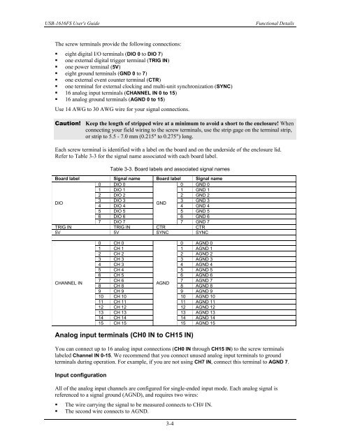
Table 3-3. Board labels and associated signal names<br />
Board label Signal name Board label Signal name<br />
0 DIO 0 0 GND 0<br />
1 DIO 1 1 GND 1<br />
2 DIO 2 2 GND 2<br />
DIO<br />
3 DIO 3 3 GND 3<br />
GND<br />
4 DIO 4 4 GND 4<br />
5 DIO 5 5 GND 5<br />
6 DIO 6 6 GND 6<br />
7 DIO 7<br />
7 GND 7<br />
TRIG IN TRIG IN CTR CTR<br />
5V 5V SYNC SYNC<br />
CHANNEL IN<br />
0 CH 0 0 AGND 0<br />
1 CH 1 1 AGND 1<br />
2 CH 2 2 AGND 2<br />
3 CH 3 3 AGND 3<br />
4 CH 3 4 AGND 4<br />
5 CH 4 5 AGND 5<br />
6 CH 5 6 AGND 6<br />
7 CH 6 7 AGND 7<br />
AGND<br />
8 CH 8 8 AGND 8<br />
9 CH 9 9 AGND 9<br />
10 CH 10 10 AGND 10<br />
11 CH 11 11 AGND 11<br />
12 CH 12 12 AGND 12<br />
13 CH 13 13 AGND 13<br />
14 CH 14 14 AGND 14<br />
15 CH 15<br />
15 AGND 15<br />
Analog input terminals (CH0 IN to CH15 IN)<br />
You can connect up to 16 analog input connections (CH0 IN through CH15 IN) to the screw terminals<br />
labeled Channel IN 0-15. We re<strong>com</strong>mend that you connect unused analog input terminals to ground<br />
terminals during operation. For example, if you are not using CH7 IN, connect this terminal to AGND 7.<br />
Input configuration<br />
All of the analog input channels are configured for single-ended input mode. Each analog signal is<br />
referenced to a signal ground (AGND), and requires two wires:<br />
• The wire carrying the signal to be measured connects to CH# IN.<br />
• The second wire connects to AGND.<br />
3-4