SEEPAGE CUT-OFFS FOR LEVEES: A ... - Geosystems, L.P.
SEEPAGE CUT-OFFS FOR LEVEES: A ... - Geosystems, L.P.
SEEPAGE CUT-OFFS FOR LEVEES: A ... - Geosystems, L.P.

Create successful ePaper yourself
Turn your PDF publications into a flip-book with our unique Google optimized e-Paper software.
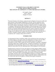
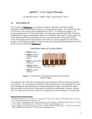
Figure 3. Typical arrangement of a backhoe wall<br />
(Soletanche Promotional Information).<br />
to the trench may be required, together with tremie placement. Where CB is used, of<br />
course, its dual purpose is to support the excavation and then to harden in place as the<br />
backfill material. For SC and SCB walls, good technique involves bringing the toe of the<br />
backfill close up to the excavated face after completion of the day’s work. The following<br />
morning, the bottom of the trench is “cleaned” (most effectively by the excavator) and a<br />
portion (say 2-5 feet) of the previous day’s backfill dug out of the trench to assure that no<br />
highly permeable “stripes” of settled sediment are left in situ. It is typical to require a 50-<br />
to 150-foot separation between backfill toe and base of excavation slope during routine<br />
work, although there seems little engineering logic for this.<br />
Most backhoe cut-offs for dams and levees have been 30-36 inches wide and not more<br />
than 60 feet deep. However, recent developments have pushed maximum “comfortable”<br />
depths to around 75 feet, while equipment has been developed to excavate to over 100<br />
feet in favorable conditions.<br />
Backfill Materials and Properties<br />
The authors recommend that detailed guidance for the design and performance of the<br />
various types of backfill mixes be obtained primarily from the classic texts, as referenced<br />
above (and especially Millet et al., 1992), and from the other case history specific<br />
accounts referenced in Bruce et al. (2006). As general background, however, the<br />
following summary is provided.<br />
CB (Self-Hardening Cement-Bentonite)<br />
There is a very wide range in the relative components of these mixes, but in general such<br />
mixes can be expected to comprise 3-4% bentonite and 15-30% cement. It is common to<br />
include a retarder, while it is often overlooked that the mix in situ may well contain up to<br />
10% or more of the native soil. An example of a mix used by Trevi as a “plastic” cut-off<br />
for a dam in North Africa comprised:<br />
– Bentonite: 45-50 kg/m 3 of mix<br />
– Cement: 200-230 kg/m 3 of mix<br />
– Water: 900-950 kg/m 3 of mix