A guide to VE configure - Zanshin
A guide to VE configure - Zanshin
A guide to VE configure - Zanshin

You also want an ePaper? Increase the reach of your titles
YUMPU automatically turns print PDFs into web optimized ePapers that Google loves.
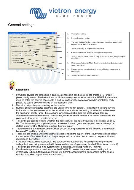
General settings<br />
2. Three-phase setting<br />
3. System frequency setting<br />
4. The scale division for shore current limit on a connected remote panel<br />
depends on the number of ‘slaves’.<br />
5. Set the sensitivity of frequency measurement.<br />
6. Connection between N and PE during inverter operation<br />
7. Voltage limits at which feedback relay opens/closes. Also, charger s<strong>to</strong>ps at<br />
lower limit.<br />
8. Determines whether the Multi should be critical of the dis<strong>to</strong>rtion in the<br />
supply waveform.<br />
9. Maximum shore current setting (is overruled by the remote panel if<br />
connected)<br />
10. Setting for use with ‘small’ genera<strong>to</strong>r<br />
Explanation<br />
1. If multiple devices are connected in parallel, a phase shift can be selected <strong>to</strong> create 2-, 3- or splitphase<br />
configuration. The first unit in a multiple-phase system must be set as the LEADER; the others<br />
must be set <strong>to</strong> the desired phase shift. If multiple units are then also connected in parallel for each<br />
phase, no setting should be made on the additional units!<br />
2. Alters the output frequency setting for the inverter.<br />
3. Number of slaves indicates that there are units connected in parallel. To maintain the shore current<br />
limit scale on the remote control for the installation as a whole, the setting must be divided between<br />
the number of parallel units. If more shore current is available than the scale allows, then an<br />
alternative value may be entered. In this case, the scale on the remote is no longer correct and it is<br />
possible <strong>to</strong> draw more current from shore.<br />
4. This setting is used <strong>to</strong> indicate whether it is necessary for the input frequency <strong>to</strong> be exactly 50 or 60<br />
Hz. This is a setting that is primarily used in conjunction with genera<strong>to</strong>rs (speed may not always be<br />
stable) <strong>to</strong> prevent the Multi from rejecting the input supply<br />
5. To permit use of a Residual Current Device (RCD). During operation as and inverter, a connection<br />
between PE and N is required.<br />
6. These are the limits at which the unit will accept or reject the supply. If the input voltage drops below<br />
the set value of the lower limit, the charger output will be reduced <strong>to</strong> the minimum <strong>to</strong> prevent further<br />
reduction of the voltage.<br />
7. If waveform detection is deselected, this au<strong>to</strong>matically activates the function preventing the lower<br />
voltage limit from being exceeded with heavy start-up loads! (previously labelled ‘Allow inrush current’)<br />
8. This setting is only active if no system panel is installed. Also keep number 3 in mind!<br />
9. If an inverter-genera<strong>to</strong>r is used, such as the HONDA EU series, the shore current setting will be<br />
dynamically reduced (following a period of low current consumption) <strong>to</strong> compensate for the engine<br />
reaction time when higher loads are activated.