bauer - Zanshin
bauer - Zanshin
bauer - Zanshin

Create successful ePaper yourself
Turn your PDF publications into a flip-book with our unique Google optimized e-Paper software.
BAUER<br />
COMPRESSORS<br />
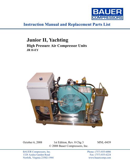
Instruction Manual and Replacement Parts List<br />
Junior II, Yachting<br />
High Pressure Air Compressor Units<br />
JR II-EY<br />
October 6, 2008 1st Edition, Rev. 0 Chg 3 MNL-0439<br />
© 2008 Bauer Compressors, Inc.<br />
BAUER Compressors, Inc. Phone: (757) 855-6006<br />
1328 Azalea Garden Road Fax: (757) 855-6224<br />
Norfolk, Virginia 23502-1944<br />
www.<strong>bauer</strong>comp.com
BAUER<br />
COMPRESSORS<br />
Junior II, Yachting<br />
This information is believed to be accurate by Bauer Compressors, Inc., as of it’s date of publication,<br />
but Bauer offers NO WARRANTY regarding the accuracy, or continuing accuracy, of the information<br />
set forth herein. Bauer shall not be liable for inaccuracies in, or consequences resulting from, your use<br />
of this information. All information supplied is in connection with sales of Bauer’s products, and is thus<br />
subject to Bauer’s standard terms and conditions of sale. Bauer reserves the right to change this information<br />
and has no obligation to update these materials. This information is © 2008 Bauer Compressors,<br />
Inc., and Bauer reserves to itself all rights to this publication. Bauer’s customers have no right to reproduce,<br />
rewrite, modify, license or permit anyone else’s use of this information, without the express written<br />
permission of Bauer Compressors, Inc.<br />
^ WARNING ^<br />
This Instruction Manual and Replacement Parts List contains safety information and instructions for the<br />
Junior II, Yachting, High Pressure Air Compressor Units.<br />
You must read, understand and follow all safety precautions and instructions.<br />
1st Edition; March 5, 2007<br />
Rev Chg Date Notes Auth<br />
0 0 03/05/2007 Derived from MNL-0252 JD<br />
0 1 05/20/2008 Change to Air Intake Filter Maintenance Procedure CLA<br />
0 2 06/16/2008<br />
Updated Replacement Parts List for P0 Purification System.<br />
Changed Valve Removal Tool P/N 00455 to 082048.<br />
Updated block to January 2008 BKM Parts List.<br />
CLA<br />
0 3 10/06/2008 Added Parts List for Drive Section SS<br />
Page i 1st Edition, Rev. 0 Chg 3
MNL-0439<br />
Table of Contents<br />
BAUER<br />
COMPRESSORS<br />
CHAPTER 1: - - - - - - - - - - - - - - - - - - - - - INTRODUCTION<br />
1.1 HOW TO USE THIS MANUAL......................................................................................................................................... 1<br />
1.1.1 Manual Safety Notices ....................................................................................................................................................... 1<br />
1.2 HOW TO USE THE REPLACEMENT PARTS LIST.................................................................................................... 2<br />
1.3 HOW TO USE THE APPENDIX....................................................................................................................................... 3<br />
1.4 COMPRESSOR UNIT PURPOSE..................................................................................................................................... 4<br />
1.5 DESIGN ................................................................................................................................................................................ 4<br />
1.6 AIR FLOW DIAGRAM...................................................................................................................................................... 6<br />
1.7 TECHNICAL SPECIFICATIONS..................................................................................................................................... 6<br />
1.8 JUNIOR II COMPRESSOR BLOCK ............................................................................................................................... 7<br />
1.8.1 JR II-E1Y/115 .................................................................................................................................................................... 7<br />
1.8.1.1 Drive Specifications........................................................................................................................................................ 7<br />
1.8.2 JR II-E1Y ........................................................................................................................................................................... 7<br />
1.8.2.1 Drive Specifications........................................................................................................................................................ 7<br />
1.8.3 JR II-E3Y ........................................................................................................................................................................... 8<br />
1.8.3.1 Drive Specifications........................................................................................................................................................ 8<br />
CHAPTER 2: - - - - - - - - - - - - - - - - - - - - - - - OPERATION<br />
2.1 PREPARATION FOR OPERATION................................................................................................................................9<br />
2.2 UNITS WITH THREE PHASE MOTOR ......................................................................................................................... 9<br />
2.3 STARTING THE UNIT. ..................................................................................................................................................... 9<br />
2.4 FILLING PROCEDURE .................................................................................................................................................... 9<br />
2.4.1 General Procedures ........................................................................................................................................................ 10<br />
2.4.2 Bottle Filling Procedures.................................................................................................................................................. 11<br />
2.4.3 Connecting to the Air Storage Bottle ............................................................................................................................... 11<br />
2.4.4 Filling the Bottle............................................................................................................................................................... 12<br />
2.4.5 Removing the Bottle......................................................................................................................................................... 12<br />
2.5 SHUT-DOWN PROCEDURES........................................................................................................................................ 12<br />
CHAPTER 3: - - - - - - - - - - - - - - - - JUNIOR II COMPRESSOR<br />
3.1 LUBRICATION................................................................................................................................................................. 13<br />
3.1.1 Oil Level Check ............................................................................................................................................................... 13<br />
3.1.2 Type of Oil .................................................................................................................................................................... 13<br />
3.1.3 Oil Changes ...................................................................................................................................................................... 14<br />
3.1.3.1 Oil Change Procedures ................................................................................................................................................. 14<br />
3.2 INTAKE FILTER.............................................................................................................................................................. 14<br />
3.2.1 Description ....................................................................................................................................................................... 14<br />
3.2.2 Maintenance ..................................................................................................................................................................... 14<br />
3.2.3 Telescope Intake Tube ..................................................................................................................................................... 15<br />
3.2.4 Intermediate Separator ..................................................................................................................................................... 15<br />
3.2.5 Maintenance ..................................................................................................................................................................... 15<br />
3.3 COMPRESSOR VALVES ................................................................................................................................................ 16<br />
3.3.1 Description ....................................................................................................................................................................... 16<br />
3.3.2 Initial Operational Check ................................................................................................................................................. 16<br />
3.3.3 Changing the Valves ........................................................................................................................................................ 16<br />
3.3.4 Changing the 1st Stage Valves......................................................................................................................................... 17<br />
October 6, 2008<br />
Page ii
BAUER<br />
COMPRESSORS<br />
Junior II, Yachting<br />
3.3.5 Changing the 2nd Stage Valves........................................................................................................................................18<br />
3.3.6 Changing the 3rd Stage Valves ........................................................................................................................................19<br />
3.4 REPAIR AND TROUBLESHOOTING...........................................................................................................................20<br />
3.4.1 General Repair Instructions..............................................................................................................................................20<br />
3.4.2 Troubleshooting Tables ...................................................................................................................................................21<br />
3.4.2.1 Electric Motor ...............................................................................................................................................................21<br />
3.4.2.2 Gasoline Engine............................................................................................................................................................21<br />
3.4.2.3 Compressor Block.........................................................................................................................................................21<br />
3.5 REPLACEMENT PARTS LIST ......................................................................................................................................23<br />
3.6 JR II YACHTING PACKAGE, ACD ..............................................................................................................................36<br />
3.6.1 Components......................................................................................................................................................................36<br />
3.6.2 Automatic Condensate Drain System Description...........................................................................................................36<br />
3.6.2.1 Condensate Drain..........................................................................................................................................................36<br />
3.6.3 ACD Maintenance............................................................................................................................................................37<br />
3.6.4 ACD Components ............................................................................................................................................................39<br />
3.6.5 Electrical Enclosure..........................................................................................................................................................44<br />
CHAPTER 4:- - - - - - - - - - - - - - - - - - - JRII MAINTENANCE<br />
4.1 MAINTENANCE RECORD.............................................................................................................................................45<br />
4.2 MAINTENANCE SCHEDULE ........................................................................................................................................45<br />
4.2.1 After the First 25 Operating Hours...................................................................................................................................45<br />
4.2.2 Every 125 Operating Hours..............................................................................................................................................46<br />
4.2.3 Every 500 Operating Hours or Annually..........................................................................................................................46<br />
4.2.4 Every 2000 Operating Hours or Biennially......................................................................................................................46<br />
4.2.5 Annually or As Required..................................................................................................................................................47<br />
4.2.6 After Repair Work............................................................................................................................................................47<br />
4.2.7 After Storage and Preservation.........................................................................................................................................49<br />
CHAPTER 5:- - - - - - - - - - - - - - - - -PURIFICATION SYSTEM<br />
5.1 GENERAL..........................................................................................................................................................................51<br />
5.1.1 General Purification System Procedures..........................................................................................................................51<br />
5.1.2 Chamber Safety Bore .......................................................................................................................................................51<br />
5.1.3 Manual Condensate Drainage...........................................................................................................................................51<br />
5.1.4 Model, Serial Number and Part Number Identification ...................................................................................................52<br />
5.1.4.1 Compressor Dataplate...................................................................................................................................................52<br />
5.1.4.2 Purification System Dataplate ......................................................................................................................................52<br />
5.1.4.3 Cartridge Installation Dataplate ....................................................................................................................................52<br />
5.1.5 Breathing Air Purification System Configurations ..........................................................................................................53<br />
5.1.6 Cartridge Operating Life ..................................................................................................................................................54<br />
5.1.6.1 Calculating the Maximum Cartridge Operating Hours.................................................................................................54<br />
5.1.6.2 Calculating the Adjusted Cartridge Operating Hours...................................................................................................54<br />
5.1.6.3 Air Purification Cartridge Operating Hours Form........................................................................................................56<br />
5.2 P0 PURIFICATION SYSTEM .........................................................................................................................................57<br />
5.2.1 Description .......................................................................................................................................................................57<br />
5.2.2 Maintenance .....................................................................................................................................................................58<br />
5.2.2.1 Replacing the Cartridge ................................................................................................................................................58<br />
5.2.2.2 Chamber Replacement Interval ...................................................................................................................................59<br />
5.2.3 Replacement Parts List.....................................................................................................................................................61<br />
Page iii 1st Edition, Rev. 0 Chg 3
MNL-0439<br />
BAUER<br />
COMPRESSORS<br />
CHAPTER 6: - - - - - - - - - - - - - - - - - - - - MISCELLANEOUS<br />
6.1 SAFETY VALVES............................................................................................................................................................. 64<br />
6.1.1 Description ....................................................................................................................................................................... 64<br />
6.1.2 Maintenance ..................................................................................................................................................................... 64<br />
6.1.2.1 Checking Function........................................................................................................................................................ 64<br />
6.1.2.2 Checking Blow Off Pressure ........................................................................................................................................ 64<br />
6.2 PRESSURE GAUGE ......................................................................................................................................................... 64<br />
6.2.1 Maintenance ..................................................................................................................................................................... 64<br />
6.3 COOLING SYSTEM......................................................................................................................................................... 64<br />
6.3.1 General ............................................................................................................................................................................. 64<br />
6.4 COMPRESSOR DRIVE SYSTEM .................................................................................................................................. 65<br />
6.4.1 Description ....................................................................................................................................................................... 65<br />
6.4.2 Checking the Drive Belt................................................................................................................................................... 65<br />
6.4.3 V-belt Tension Adjustment .............................................................................................................................................. 65<br />
6.4.4 Electric Motor Maintenance............................................................................................................................................. 66<br />
6.5 ELECTRICAL SYSTEM.................................................................................................................................................. 66<br />
6.5.1 Description ....................................................................................................................................................................... 66<br />
6.5.2 Drive Motor...................................................................................................................................................................... 66<br />
6.6 JR II ELECTRIC DRIVE REPLACEMENT PARTS .................................................................................................. 67<br />
CHAPTER 7: - - - - - - - - - - - - - - - - - - - - - - - - APPENDIX<br />
7.1 SAFETY.............................................................................................................................................................................. 68<br />
7.1.1 General Safety Precautions .............................................................................................................................................. 68<br />
7.1.2 Safety Warning Labels..................................................................................................................................................... 70<br />
7.2 INSTALLATION............................................................................................................................................................... 71<br />
7.2.1 Corrosion Resistance........................................................................................................................................................ 71<br />
7.2.2 Outdoor Location ......................................................................................................................................................... 71<br />
7.2.3 Indoor Location ................................................................................................................................................................ 71<br />
7.2.3.1 Electrical Installation.................................................................................................................................................... 71<br />
7.3 STORAGE AND PRESERVATION............................................................................................................................... 72<br />
7.3.1 Storage.............................................................................................................................................................................. 72<br />
7.3.2 Preservation...................................................................................................................................................................... 73<br />
7.3.2.1 Preparation for Preservation ......................................................................................................................................... 73<br />
7.3.2.2 Preserving the Compressor........................................................................................................................................... 73<br />
7.3.2.3 Preserving the Motor or Engine.................................................................................................................................... 73<br />
7.3.2.4 Preventive Maintenance During Storage...................................................................................................................... 73<br />
7.3.2.5 Reactivating the Compressor Unit................................................................................................................................ 74<br />
7.4 TABLES AND REFERENCE DATA .............................................................................................................................. 75<br />
7.4.1 Tightening Torque Values ............................................................................................................................................ 75<br />
7.4.2 Pipe Connections (swivel nuts)........................................................................................................................................ 75<br />
October 6, 2008<br />
Page iv
BAUER<br />
COMPRESSORS<br />
List of Figures<br />
Junior II, Yachting<br />
CHAPTER 1:- - - - - - - - - - - - - - - - - - - - - INTRODUCTION<br />
Figure 1-1 Junior II Yachting Package; Front...........................................................................................................................4<br />
Figure 1-2 Junior II Yachting Package; Rear............................................................................................................................5<br />
Figure 1-3 Internal Air Flow Diagram ......................................................................................................................................6<br />
CHAPTER 2:- - - - - - - - - - - - - - - - - - - - - - - OPERATION<br />
Figure 2-1 Air Storage Bottle Valve Operating Sequence ......................................................................................................11<br />
CHAPTER 3:- - - - - - - - - - - - - - - - JUNIOR II COMPRESSOR<br />
Figure 3-1 Oil Dipstick Markings ...........................................................................................................................................13<br />
Figure 3-2 Intake Filter............................................................................................................................................................14<br />
Figure 3-3 Intermediate Separator...........................................................................................................................................15<br />
Figure 3-4 Valve Function.......................................................................................................................................................16<br />
Figure 3-5 1st Stage Plate Valve .............................................................................................................................................16<br />
Figure 3-6 1st Stage Valve Head.............................................................................................................................................17<br />
Figure 3-7 2nd Stage Valve Head ...........................................................................................................................................18<br />
Figure 3-8 3rd Stage Valve Head ............................................................................................................................................19<br />
Figure 3-9 Removing the 3rd Stage Valves ............................................................................................................................20<br />
Figure 3-10 Crankcase, Driving Gear and Fanwheel ................................................................................................................23<br />
Figure 3-11 Pistons and Cylinders ............................................................................................................................................25<br />
Figure 3-12 Valve Heads and Valves........................................................................................................................................27<br />
Figure 3-13 Cooler ....................................................................................................................................................................29<br />
Figure 3-14 Intake Filter and Intermediate Separator ...............................................................................................................31<br />
Figure 3-15 Frame with Accessories.........................................................................................................................................33<br />
Figure 3-16 Special Tools .........................................................................................................................................................35<br />
Figure 3-17 Internal Air Flow Diagram; JRII Yachting............................................................................................................37<br />
Figure 3-18 ACD System ..........................................................................................................................................................39<br />
Figure 3-19 ACD Replacement Parts List; Solenoid ................................................................................................................40<br />
Figure 3-20 ACD Replacement Parts List; PO Purification System.........................................................................................41<br />
Figure 3-21 ACD Replacement Parts List; Intermediate Separator ..........................................................................................42<br />
Figure 3-22 ACD Replacement Parts List; ACD Collector ......................................................................................................43<br />
Figure 3-23 NEMA 4X Electrical Enclosure ............................................................................................................................44<br />
CHAPTER 4:- - - - - - - - - - - - - - - - - - - JRII MAINTENANCE<br />
There are no Figures in this Chapter<br />
CHAPTER 5:- - - - - - - - - - - - - - - - -PURIFICATION SYSTEM<br />
Figure 5-1 Cartridge Safety Venting .......................................................................................................................................51<br />
Page v 1st Edition, Rev. 0 Chg 3
BAUER<br />
COMPRESSORS<br />
Figure 5-2 Purification System Dataplates (typical)............................................................................................................... 52<br />
Figure 5-3 Correction Factor for Cartridge Operating Hours ................................................................................................. 55<br />
Figure 5-4 Example Record of Adjusted Operating Hours..................................................................................................... 55<br />
Figure 5-5 P0 Purification Chamber ....................................................................................................................................... 57<br />
Figure 5-6 P0 Purification System Cross Section ................................................................................................................... 58<br />
Figure 5-7 P0 Purification System Parts List.......................................................................................................................... 61<br />
Figure 5-8 Pressure Maintaining Valve .................................................................................................................................. 63<br />
MNL-0439<br />
CHAPTER 6: - - - - - - - - - - - - - - - - - - - - MISCELLANEOUS<br />
Figure 6-1 Final Pressure Safety Valve................................................................................................................................... 64<br />
Figure 6-2 Gauges ................................................................................................................................................................... 64<br />
Figure 6-3 Checking V-belt Tension....................................................................................................................................... 65<br />
Figure 6-4 V-belt Pulley Alignment........................................................................................................................................ 65<br />
Figure 6-5 Electric Motor Adjustment.................................................................................................................................... 65<br />
Figure 6-6 JR II, Electric Drive............................................................................................................................................... 67<br />
CHAPTER 7: - - - - - - - - - - - - - - - - - - - - - - - - APPENDIX<br />
Figure 7-1 Incoming Power Wiring Label .............................................................................................................................. 72<br />
October 6, 2008<br />
Page vi
BAUER<br />
COMPRESSORS<br />
CHAPTER 1:<br />
INTRODUCTION<br />
Junior II, Yachting<br />
1.1 How To Use This Manual<br />
This manual contains the operating and maintenance instructions for the Bauer Compressors, Inc. product(s)<br />
listed on the front cover.<br />
All instructions in this manual should be observed and carried out as written to prevent damage or premature<br />
wear to the product or the equipment served by it.<br />
If your unit is equipped with nonstandard accessories and/or options, supplemental information is normally<br />
included in other documentation; i.e. OEM Manuals or additional Bauer Manuals.<br />
While every effort is made to ensure the accuracy of the information contained in this manual, Bauer<br />
Compressors, Inc. will not, under any circumstances be held accountable for any inaccuracies or the<br />
consequences thereof.<br />
1.1.1 Manual Safety Notices<br />
Important instructions concerning the endangerment of personnel, technical safety or operator safety<br />
will be specially emphasized in this manual by placing the information in the following types of safety<br />
notices.<br />
^ DANGER ^<br />
DANGER indicates an imminently hazardous situation which, if not avoided, will result in death or<br />
serious injury. This is limited to the most extreme situations.<br />
^ WARNING ^<br />
WARNING indicates a potentially hazardous situation which, if not avoided, could result in death<br />
or injury.<br />
^ CAUTION ^<br />
CAUTION indicates a potentially hazardous situation which, if not avoided, may result in minor or<br />
moderate injury. It may also be used to alert against unsafe practices.<br />
^ NOTE ^<br />
NOTE advise of technical requirements that require particular attention by the operator or the<br />
maintenance technician for proper maintenance and utilization of the equipment.<br />
Page 1 1st Edition, Rev. 0 Chg 3
MNL-0439<br />
BAUER<br />
COMPRESSORS<br />
1.2 How to Use the Replacement Parts List<br />
• A lozenge ◊ in the Item Number column indicates the part number for a complete assembly.<br />
• A dagger (†) in the Qty column with or without an ellipsis (…) in the Part Number column means the<br />
part is illustrated for assembly purposes only and is not available for sale as an individual component.<br />
This part can be obtained by ordering the complete assembly.<br />
• AR in the Qty column means that the item is cut or manufactured to the size which the customer specifies.<br />
• A dash (—) in the Item Number column indicates that there is more than one part number applicable<br />
to the preceding Item Number.<br />
• The letter(s) in the columns labeled Kit indicate the number of operating hours when the part is to be<br />
replaced; a = replaced every 1,000 hours, b = replaced every 2,000 hours and c= replaced every 4,000<br />
hours.<br />
• NS in the Item Number column indicates the part is not illustrated but is available.<br />
When placing an order for spare parts, please provide the following information to ensure delivery of<br />
the correct parts. The model number, date of manufacture and serial number can be found of the compressor<br />
unit identification plate on the compressor unit’s frame.<br />
Information<br />
Model Number<br />
Example<br />
TCOM25<br />
Serial Number 32165<br />
Date of Manufacture 02/2005<br />
Quantity required 2<br />
Part Number<br />
N04860<br />
Part Description Valve<br />
^ WARNING ^<br />
The use of repair parts other than those included in the Bauer Replacement Parts Lists may create unsafe<br />
conditions over which Bauer has no control. Such unsafe conditions can lead to accidents that may be lifethreatening,<br />
cause substantial bodily injury, and/or result in damage to the equipment. Therefore, BAUER<br />
Compressors, Inc. can bear no responsibility for equipment in which unapproved repair parts are installed.<br />
October 6, 2008 Page 2
BAUER<br />
COMPRESSORS<br />
1.3 How to Use the Appendix<br />
Information contained in the Appendix to this manual includes the following.<br />
Junior II, Yachting<br />
• The safety instructions applicable to this product. They must be read, understood and complied with<br />
prior to operating the product.<br />
• The instructions for installing this product. They must be read, understood and complied with prior to<br />
operating the product.<br />
• The instructions for long term storage (over 90 days) of this product.<br />
Page 3 1st Edition, Rev. 0 Chg 3
MNL-0439<br />
1.4 Compressor Unit Purpose<br />
The JR II-EY is designed to compress air for breathing as required in diving applications.<br />
1.5 Design<br />
The Junior II compressor unit consists of the following major assemblies.<br />
• Compressor Block<br />
• Electric Motor Drive<br />
• P0 Purification System<br />
• Automatic Condensate Drain System<br />
• Fill Hose Assembly<br />
• Base Plate and Frame<br />
BAUER<br />
COMPRESSORS<br />
Figure 1-1<br />
Junior II Yachting Package; Front<br />
5 6 7<br />
1<br />
2<br />
8<br />
1. Reset Plunger<br />
2. NEMA 4X Electrical Enclosure<br />
3. Electric Motor<br />
4. Stainless Steel Base<br />
3 4<br />
5. Air Intake Filter<br />
6. Oil Dip Stick<br />
7. Final Pressure Valve<br />
8. Condensate Collector<br />
October 6, 2008 Page 4
BAUER<br />
COMPRESSORS<br />
Junior II, Yachting<br />
Figure 1-2<br />
Junior II Yachting Package; Rear<br />
4<br />
2 3<br />
5<br />
1<br />
6<br />
1. P0 Purification System<br />
2. Oil Dip Stick<br />
3. Intake Air Filter<br />
4. On/Off Switch<br />
5. Hour Meter<br />
6. V-Belt Cover<br />
Page 5 1st Edition, Rev. 0 Chg 3
MNL-0439<br />
BAUER<br />
COMPRESSORS<br />
Figure 1-3<br />
Internal Air Flow Diagram<br />
12<br />
13<br />
1<br />
6<br />
14<br />
11<br />
9<br />
2<br />
3<br />
10<br />
17<br />
8<br />
5<br />
4<br />
15<br />
16<br />
15<br />
1. Compressor Air Intake Extensions<br />
2. Intake Filter<br />
3. 1st Stage Cylinder<br />
4. 2nd Stage Cylinder<br />
5. 3rd Stage Cylinder<br />
6. 1st/2nd Stage Intercooler<br />
7. 2nd/3rd Stage Intercooler<br />
8. Intermediate Separator<br />
9. After Cooler<br />
7<br />
10. 1st Stage Safety Valve<br />
11. 2nd Stage Safety Valve<br />
12. Final Pressure Safety Valve<br />
13. P0 Filter System<br />
14. Triplex ® Longlife Cartridge<br />
15. Condensate Drain Valve<br />
16. Pressure Maintaining Valve<br />
17. Fill Hose<br />
1.6 Air Flow Diagram<br />
See Figure 1-3. The air is drawn in through the Telescopic Tube (1) (Required for units with gasoline<br />
engine and recommended for those with electric motors) through the Intake Filter (2) and is compressed<br />
to final pressure in the Cylinders (3, 4 and 5). It is re-cooled by the Intercoolers (6 and 7) and the Aftercooler<br />
(9). The pressure of the individual stages is controlled by Safety Valves (10 and 11). The compressed<br />
air is cleaned in the Intermediate Separator (8) and purified in the P0 Filter System (13). The<br />
Intermediate Separator and P0 Filter System are drained by the Condensate Drain Valves (15). The<br />
Pressure Maintaining Valve (16) provides a constant pressure within the P0 Filter System. The purified<br />
compressed air then passes through the Fill Hose (17) and Fill Valve (18) to the bottles to be filled. Fill<br />
pressure is indicated by the Final Pressure Gauge (19).The Final Safety Valve (12) is adjusted to blow<br />
off at the pressure selected.<br />
1.7 Technical Specifications<br />
All technical specifications are subject to change without prior notice or obligation. The Charging Rate<br />
is based upon recharging an 80 cubic foot bottle from 500 to 3,000 PSIG. The Free Air Delivered is<br />
compressor capacity referenced to standard inlet conditions.<br />
October 6, 2008 Page 6
BAUER<br />
COMPRESSORS<br />
Junior II, Yachting<br />
1.8 Junior II Compressor Block<br />
Number of stages 3<br />
Number of cylinders 3<br />
1st Stage Cylinder Bore<br />
2.36 in (60mm)<br />
2nd Stage Cylinder Bore<br />
1.10 in (28mm)<br />
3rd Stage Cylinder Bore<br />
0.47 in (12mm)<br />
Piston Stroke<br />
0.95 in (24 mm)<br />
Intermediate Pressure 1st stage<br />
73 - 87 psig (5 - 6 bar)<br />
Intermediate Pressure 2nd stage<br />
580 - 725 psig (40 - 50 bar)<br />
Compressor Block Oil Capacity<br />
12 fluid ounces (400 cc)<br />
Method of Lubrication<br />
Splash<br />
Maximum Ambient Temperature 41° - 113°F (5°-45° C)<br />
Maximum Permissible Inclination of Compressor 1 5°<br />
Maximum Speed<br />
2300 rpm (min.-1)<br />
1.8.1 JR II-E1Y/115<br />
Medium<br />
Intake Pressure<br />
Charging Rate<br />
Free Air Delivered<br />
Maximum Operating Pressure<br />
Package Weight<br />
1.8.1.1 Drive Specifications<br />
Motor P/N<br />
Operating Voltage<br />
Horsepower<br />
Speed<br />
Type<br />
1.8.2 JR II-E1Y<br />
Medium<br />
Intake Pressure<br />
Charging Rate<br />
Free Air Delivered<br />
Maximum Operating Pressure<br />
Package Weight<br />
1.8.2.1 Drive Specifications<br />
Motor P/N<br />
Operating Voltage<br />
Horsepower<br />
Speed<br />
Type<br />
Air<br />
Atmospheric<br />
2.9 SCFM<br />
2.5 SCFM<br />
5,000 psi (350 bar)<br />
92 lbs (41.8 Kg)<br />
MTR-0025<br />
115 - 230VAC, Single Phase, 60 Hz<br />
2.0 HP<br />
1,500 RPM<br />
ODP<br />
Air<br />
Atmospheric<br />
3.9 SCFM<br />
3.2 SCFM<br />
5,000 psig (350 bar)<br />
89 lbs (40.5 Kg)<br />
MTR-0093<br />
230VAC, Single Phase, 60 Hz<br />
3 HP<br />
2100 RPM<br />
ODP<br />
1. This value is valid only if the compressor block oil in normal level position corresponds with the upper mark of the oil dipstick and may not be exceeded.<br />
Page 7 1st Edition, Rev. 0 Chg 3
MNL-0439<br />
1.8.3 JR II-E3Y<br />
Medium<br />
Intake Pressure<br />
Charging Rate<br />
Free Air Delivered<br />
Maximum Operating Pressure<br />
Package Weight<br />
1.8.3.1 Drive Specifications<br />
Motor P/N<br />
Operating Voltage<br />
Horsepower<br />
Speed<br />
Type<br />
Air<br />
Atmospheric<br />
3.9 SCFM<br />
3.2 SCFM<br />
5,000 psi (350 bar)<br />
111 lbs (50.5 Kg)<br />
MTR-0028F2<br />
208 - 430 VAC, Three Phase, 60 Hz<br />
3.0 HP<br />
3600 RPM<br />
ODP, F2<br />
BAUER<br />
COMPRESSORS<br />
October 6, 2008 Page 8
BAUER<br />
COMPRESSORS<br />
CHAPTER 2: OPERATION<br />
Junior II, Yachting<br />
2.1 Preparation for Operation<br />
Prior to operating the unit for the first time, read this Instruction Manual carefully.<br />
1. Make sure that all persons operating the compressor unit and associated equipment are familiar with<br />
the function of all controls and indicators.<br />
2. Thoroughly comply with the paragraph titled Fundamental Safety Notices contained in the Introduction<br />
section of this manual.<br />
3. If the unit has been out of service for two years or more and uses synthetic compressor oil change<br />
the compressor oil. If the unit uses petroleum based compressor oil change it after being out of service<br />
one year.<br />
4. During the initial operation or prior to operation subsequent to repairs operate the unit for at least<br />
five minutes with open outlet valve (unpressurized) to ensure proper lubrication of all parts before<br />
pressure is built up.<br />
5. Prior to each operation check the oil level according to Section 2 Lubrication and determine<br />
whether maintenance is necessary in accordance with Section 13.<br />
6. Every time the unit is started, check all systems for proper operation. If any malfunction is observed<br />
stop the unit immediately and find the cause of the fault or call the service department.<br />
2.2 Units with Three Phase Motor<br />
1. Immediately after switching on the unit for the first time check the direction of rotation of the motor<br />
for compliance with the arrow on the compressor unit.<br />
2. If it is turning the compressor in the wrong direction the phases are not connected properly.<br />
3. Shut down the unit and interchange two of the three phase leads from the switch box.<br />
4. Never change leads from the motor.<br />
2.3 Starting the Unit.<br />
To start the unit turn the “On/Off” switch to the ON position. The switch should illuminate showing<br />
power is flowing to the motor. When final pressure is reached and the safety valve blows off excess<br />
pressure. The unit is then ready for operation. Check final pressure safety valve and pressure gauge.<br />
The unit is now ready for filling operations.<br />
2.4 Filling Procedure<br />
^ WARNING ^<br />
Ensure the intake air is free from noxious gas, exhaust fumes and solvent vapors. On units employing a<br />
gasoline engine it is most important to use an intake hose for this purpose. It is also recommended that the<br />
intake hose be used with units driven by electric motor.<br />
Page 9 1st Edition, Rev. 0 Chg 3
MNL-0439<br />
BAUER<br />
COMPRESSORS<br />
2.4.1 General Procedures<br />
^ WARNING ^<br />
Never open fill valves or shut off valves when under pressure and the hose is not connected as discharging<br />
high pressure compressed air can cause serious accidents.<br />
^ WARNING ^<br />
Fill hoses must be in satisfactory condition and the threads must be undamaged. Pay particular attention to<br />
the interface from hose fitting to hose. If the rubber is scored, the hose must be discarded, otherwise water<br />
can corrode the wire gauze causing a hose failure.<br />
1. The fill valve connection is of the manual type permitting connection to the air tank without tools.<br />
An O-ring is provided for sealing purposes.<br />
2. Compressed air tank fill valves for pressure in excess of 2900 psi (200 bar) are standardized and<br />
connectors for 2900 psi (200 bar) and 4400 psi (300 bar) are different and can not be mixed up.<br />
3. To ensure safe air tank removal after filling, the fill valve has an integral venting bore. Therefore<br />
always close the tank valve before closing the fill valve.<br />
4. During the fill procedure the bottles will warm up due to recompression.<br />
5. After filling, remove and allow the bottle to cool down. When it is cool the bottle may be reconnected<br />
and topped up to its maximum filling pressure.<br />
October 6, 2008 Page 10
BAUER<br />
COMPRESSORS<br />
2.4.2 Bottle Filling Procedures<br />
See Figure 2-1<br />
Junior II, Yachting<br />
^ WARNING ^<br />
Do not attach bottles to 4350 psi (300 bar) units unless the bottle is rated for this pressure. (Note pressure<br />
stamped on the tank neck)<br />
^ WARNING ^<br />
Never open the fill valve unless the bottle is connected to the fill hose. Whipping of an unrestrained hose<br />
caused by high pressure air discharge can cause serious injury!<br />
^ CAUTION ^<br />
The filling procedure should not be interrupted for more than 10 minutes to avoid increased CO2 levels in<br />
the air filling the bottle.<br />
Figure 2-1<br />
Air Storage Bottle Valve Operating Sequence<br />
2.<br />
1.<br />
1.<br />
2.<br />
Attaching the Fill Yoke<br />
Opening Sequence<br />
Closing Sequence<br />
2.4.3 Connecting to the Air Storage Bottle<br />
1. Ensure both the fill valve and bottle valve are closed<br />
2. Connect the air bottle to the compressor fill hose utilizing the fill yoke.<br />
Page 11 1st Edition, Rev. 0 Chg 3
MNL-0439<br />
2.4.4 Filling the Bottle<br />
1. First open fill valve. (1)<br />
2. Open bottle valve. (2)<br />
3. Bottle will begin filling.<br />
4. During the filling process, monitor bottle pressure on fill valve gauge.<br />
BAUER<br />
COMPRESSORS<br />
2.4.5 Removing the Bottle<br />
1. First close the bottle valve. (1)<br />
2. Close the fill valve. (2)<br />
3. Remove fill yoke and store compressed air bottle.<br />
2.5 Shut-Down Procedures<br />
First close the fill valve.<br />
1. Turn off electrical power with the appropriate switch<br />
2. Vent unit to approximately 1,150 psi (80 bar).<br />
3. Decompress with drain valves to remove all moisture in the filter and the oil and water separator.<br />
4. Close all drain valves again.<br />
5. Check the oil level in the compressor and top up, if necessary.<br />
6. Also check operating hours to see if the compressor needs servicing in accordance with the maintenance<br />
schedule.<br />
October 6, 2008 Page 12
BAUER<br />
COMPRESSORS<br />
CHAPTER 3:<br />
3.1 Lubrication<br />
JUNIOR II COMPRESSOR<br />
3.1.1 Oil Level Check<br />
Check the oil level prior to putting compressor into operation each day<br />
1. Remove dipstick and wipe dry.<br />
2. Reinsert the dipstick ensuring that it is completely seated.<br />
Junior II, Yachting<br />
3. Withdraw the dipstick again and note the oil level.<br />
The level should be between the minimum and maximum marks on the dipstick.See Figure 3-1.<br />
Figure 3-1<br />
Oil Dipstick Markings<br />
Max.<br />
Min.<br />
3.1.2 Type of Oil<br />
^ CAUTION ^<br />
The oil level must not go down below the minimum mark but also must not exceed the maximum<br />
mark as this will cause excessive lubrication of the compressor and result in the valves carbonizing.<br />
^ NOTE ^<br />
The part number for the oil delivered in all Junior II compressor units is BAUER part number:<br />
OIL-0024<br />
Due to the thermal load on the compressor, only high quality oil should be used. It is recommended that<br />
you restrict oil to BAUER P/N OIL-0024 which has a proven record of success and is specified for this<br />
compressor.<br />
Page 13 1st Edition, Rev. 0 Chg 3
MNL-0439<br />
BAUER<br />
COMPRESSORS<br />
3.1.3 Oil Changes<br />
The oil must be changed every 2,000 operating hours or every two years whichever is reached first.<br />
3.1.3.1 Oil Change Procedures<br />
1. Run the compressor until it reaches normal operating temperature.<br />
2. Remove the oil dipstick from oil filler tube.<br />
3. While the oil is still warm, remove oil drain plug and drain oil into an appropriate container.<br />
4. After oil has completely drained, reinstall oil drain plug and tighten.<br />
5. Refill with 12 Fluid Ounces (360 cc) of oil, through the oil filler tube.<br />
6. Check oil level using the oil dipstick.<br />
7. Oil level is correct if it is at the upper mark.See Figure 3-1<br />
3.2 Intake Filter<br />
3.2.1 Description<br />
A dry micronic filter is used to filter the intake air. See Figure 3-2<br />
Figure 3-2<br />
Intake Filter<br />
5<br />
4<br />
3<br />
2<br />
1<br />
1. Knurled Nut<br />
2. Plastic Cap<br />
3. Filter Cartridge<br />
4. O-ring<br />
5. Intake Opening<br />
3.2.2 Maintenance<br />
The filter cartridge must be changed at regular intervals according to the maintenance schedule.<br />
1. Remove knurled nut (1) and take off plastic cap (2).<br />
2. Clean the inside of the filter housing with a damp cloth. Take care to prevent dust from entering the<br />
opening into the compressor.<br />
3. Replace filter cartridge with a new filter cartridge.<br />
4. Inspect O-ring (4) and replace if damaged.<br />
5. Replace plastic cap and tighten knurled nut<br />
October 6, 2008 Page 14
BAUER<br />
COMPRESSORS<br />
Junior II, Yachting<br />
3.2.3 Telescope Intake Tube<br />
See Figure 3-2. The telescopic intake tube is inserted in the intake opening (5). This is necessary to<br />
ensure clean intake air on engine driven compressor units. It’s use is also recommended with electric<br />
motor driven compressor units.<br />
3.2.4 Intermediate Separator<br />
An intermediate separator is mounted on the compressor block. This separator is designed to remove oil<br />
and water which accumulates due to the cooling of the medium after the compression process. Separation<br />
is achieved by means of centrifugal action provided by a vortex plate (1)<br />
Figure 3-3<br />
Intermediate Separator<br />
3<br />
1<br />
2<br />
4<br />
1. Vortex Plate<br />
2. Hollow Screw<br />
3. O-ring<br />
4. Knurled Nut<br />
^ WARNING ^<br />
The rapid depressurizing and repressurizing of the intermediate separator during condensate draining<br />
subjects it to metallurgical stresses. To prevent catastrophic failure with the possibility of damage,<br />
injury or death the intermediate separator must be replaced after 85,000 load cycles. A load<br />
cycle equals one depressurization- repressurization. The Bauer recommended frequency of condensate<br />
draining is every fifteen minutes and is a balance between maximizing the life of the oil<br />
and water separator chamber and maintaining the quality of the delivered air.<br />
3.2.5 Maintenance<br />
The Intermediate Separator P/N 081798 requires no maintenance.<br />
Page 15 1st Edition, Rev. 0 Chg 3
S<br />
MNL-0439<br />
3.3 Compressor Valves<br />
BAUER<br />
COMPRESSORS<br />
3.3.1 Description<br />
The valve heads of the individual stages form the top part of the cylinders. The intake and pressure valves<br />
are fitted inside the valve heads. (Note that the valves are operated by air flow. (See Figure 3-4). On the<br />
suction stroke, the intake valve is opened and air flows into the cylinder. At the start of the compression<br />
stroke the intake valve closes. the end of the compression stroke the compressed air forces the pressure<br />
valve open.<br />
The 1st Stage combines the intake and pressure valves in a plate valve. (See Figure 3-5).<br />
Figure 3-4 Valve Function Figure 3-5 1st Stage Plate Valve<br />
Discharge<br />
Side<br />
Intake<br />
Side<br />
To<br />
2nd<br />
Stage<br />
N4860-F98<br />
From<br />
Intake<br />
Filter<br />
Intake<br />
Discharge<br />
3.3.2 Initial Operational Check<br />
After maintenance work on the valves, the valves should be checked for proper operation. Note that the<br />
intake line to the valve heads is warm and the outlet piping should be hot. This indicates the valves are<br />
operating correctly.<br />
3.3.3 Changing the Valves<br />
• Always replace the valves as a complete set.<br />
• Observe the correct sequence when reassembling.<br />
• Check individual components for excessive wear. If the valve seat and valve disks are dented, replace<br />
the valves.<br />
• Valve head screws must be tightened with a torque wrench.<br />
• Check the valve space in the valve head for dirt and clean if necessary.<br />
• Thirty minutes after restarting the compressor unit, stop the unit, let it cool to ambient temperature<br />
and retighten the valve studs and cap nuts. Otherwise valves could work loose due to the setting of the<br />
gaskets.<br />
October 6, 2008 Page 16
BAUER<br />
COMPRESSORS<br />
Junior II, Yachting<br />
• After finishing all maintenance work on the valves, turn the compressor by hand using the flywheel<br />
and check that all items have been correctly installed.<br />
• Remove and check the valves every 1,000 operating hours.<br />
• Replace the valves every 2,000 operating hours to avoid fatigue failure<br />
Figure 3-6<br />
1st Stage Valve Head<br />
7<br />
6<br />
1<br />
5<br />
2<br />
3<br />
4<br />
1. Valve Head<br />
2. Gasket<br />
3. Plate Valve<br />
4. O-ring<br />
5. Valve Head<br />
Screw<br />
6. Washer<br />
7. Hex Nut<br />
3.3.4 Changing the 1st Stage Valves<br />
• Loosen the two cap nuts from tube connectors and remove after-cooler.<br />
• Remove four valve head screws (5) from valve head (1). Remove valve head.<br />
• Remove gasket (2) and plate valve (3).<br />
• When reinstalling the plate valve, check that the mark “S” is facing upwards and towards the inlet<br />
filter side. The cross bar of the gasket (2) provides a seal between the inlet and pressure opening of<br />
the plate valve.<br />
Page 17 1st Edition, Rev. 0 Chg 3
MNL-0439<br />
BAUER<br />
COMPRESSORS<br />
Figure 3-7<br />
2nd Stage Valve Head<br />
1<br />
2<br />
3<br />
8<br />
7<br />
4<br />
6<br />
5<br />
1. Nut<br />
2. Washer<br />
3. Valve Cover Plate<br />
4. Stud<br />
5. Valve Head<br />
6. O-rings<br />
7. Intake Valve<br />
8. Pressure Valve<br />
3.3.5 Changing the 2nd Stage Valves<br />
Both the intake and pressure valves can be serviced from the top of the head. See Figure 3-7.<br />
1. Remove two captive nuts (1) and spring washers (2)<br />
2. Remove valve cover plate (3)<br />
3. Remove valves (7 and 8) using two screwdrivers as shown in Figure 3-9<br />
4. Reassemble in reverse sequence. Position spring washers so the curved side is facing up. Fasten<br />
nuts so the valve cover plate is parallel to the valve head. Torque to 7 ft-lbs (10Nm).<br />
October 6, 2008 Page 18
BAUER<br />
COMPRESSORS<br />
Junior II, Yachting<br />
3.3.6 Changing the 3rd Stage Valves<br />
On this valve head, the valves are arranged on the upper and lower side due to the small diameter of the<br />
3rd Stage head. See Figure 3-8.<br />
Figure 3-8<br />
3rd Stage Valve Head<br />
7<br />
8<br />
1<br />
2<br />
3<br />
4<br />
5<br />
6<br />
1. Torque Stud<br />
2. Valve Cover<br />
3. Pressure Valve<br />
4. O-ring<br />
5. Valve Head<br />
6. Intake Valve<br />
7. Allen Screw<br />
8. Washer<br />
^ CAUTION ^<br />
Always change the intake and pressure valves of the 3rd Stage at the same time.<br />
1. To remove or install the intake valve (6) use the special tool which is part of tool set delivered with<br />
the unit. (See Figure 3-16.)<br />
2. The pressure valve (3) is merely inserted into the valve head (5). It is sealed by the O-Ring (4) and<br />
fixed to the valve head by the torque stud (1).<br />
3. Remove pressure valve by loosening torque stud (1) a couple of turns.<br />
Page 19 1st Edition, Rev. 0 Chg 3
MNL-0439<br />
4. Remove Allen screws (7) and take off valve head cover (6).<br />
BAUER<br />
COMPRESSORS<br />
5. To lift pressure valve out of valve head put two flat head screwdrivers into grooves of the pressure<br />
valve body. See Figure 3-9. If necessary turn valve to loosen it, using a 13mm open end wrench on<br />
the flat surfaces of the valve.<br />
6. Lift out pressure valve (3) together with O-Ring (4).<br />
7. Check O-Ring for damage and wear, replace if necessary. Put O-ring into the valve head.<br />
8. To reinstall pressure valve Insert valve (3) and install valve head cover (6).<br />
9. Fasten valve head cover to valve head with Allen screws and washers (8).<br />
10. Screw in torque stud (1) and torque to 14 ft-lbs (20Nm).<br />
Figure 3-9<br />
Removing the 3rd Stage Valves<br />
Pressure Valve<br />
Intake Valve<br />
3.4 Repair and Troubleshooting<br />
3.4.1 General Repair Instructions<br />
Preventive maintenance usually involves replacing the valves, gaskets and sealing rings as well as carrying<br />
out the maintenance work.<br />
Repair work can be carried out on the compressor block to a certain extent but a certain experience and<br />
skill level is necessary.<br />
It should be noted however, that<br />
• No repair should be carried out on the crankshaft or bearings.<br />
• Safety valves are not repaired but always replaced completely.<br />
October 6, 2008 Page 20
BAUER<br />
COMPRESSORS<br />
Junior II, Yachting<br />
3.4.2 Troubleshooting Tables<br />
3.4.2.1 Electric Motor<br />
TROUBLE CAUSE REMEDY<br />
Motor will not start<br />
Electric circuitry faulty<br />
Motor runs eccentrically V-belt worn Replace V-belt<br />
Motor protection switch turns<br />
unit off<br />
Insufficient voltage because of a<br />
weak power supply.<br />
Power supply cable to long or too<br />
small in diameter<br />
Check all fuses, terminal connections,<br />
wire leads, make sure that<br />
motor data complies with mains<br />
supply.<br />
Switch off other power consuming<br />
devices.<br />
Replace with suitable cable<br />
3.4.2.2 Gasoline Engine<br />
TROUBLE CAUSE REMEDY<br />
Engine will not start See engine instruction See engine instructions<br />
Engine runs eccentrically V-belt worn Replace V-belt<br />
Excessive V-belt wear V-belt tension incorrect Retighten<br />
Pulleys not aligned<br />
Readjust<br />
3.4.2.3 Compressor Block<br />
TROUBLE CAUSE REMEDY<br />
Compressor does not attain final<br />
pressure.<br />
Condensate drain valve(s) leaking<br />
Final pressure safety valve<br />
defective (blows to soon)<br />
No cartridge in P21 Filter system.<br />
(air escaping through the<br />
cartridge safety bore.)<br />
Vent screw for final pressure<br />
safety valve not in operating<br />
position.<br />
Tighten and reseal.<br />
Replace safety valve<br />
Replace cartridge<br />
To vent, unscrew until completely<br />
open.<br />
Page 21 1st Edition, Rev. 0 Chg 3
MNL-0439<br />
BAUER<br />
COMPRESSORS<br />
Air delivery drops Intake filter soiled Clean or replace filter cartridge.<br />
Intermediate pressure safety<br />
valve blows<br />
Air escaping through the cartridge<br />
safety bore<br />
Pipe coupling leaking<br />
Excessive wear of the 3rd stage<br />
piston<br />
Intermediate pressure too high<br />
because of defective inlet or<br />
pressure valve of the following<br />
stage.<br />
Safety valve leaking<br />
Cartridge missing<br />
Cartridge O-rings defective<br />
Retighten couplings.<br />
Replace piston and sleeve of 3rd<br />
stage.<br />
Check and replace inlet or pressure<br />
valve.<br />
Replace safety valve.<br />
Replace cartridge<br />
Check and replace O-rings<br />
Taste of oil in the air Cartridge saturated Replace cartridge<br />
Compressor overheats<br />
Unqualified lubricant being used<br />
Insufficient cooling air<br />
Ambient temperature too high.<br />
Direction of rotation is incorrect.<br />
Inlet and pressure valve of one<br />
stage is leaking<br />
Replace with approved oil.<br />
Inlet and pressure valve of one<br />
stage leaking. Or direction of<br />
rotation incorrect.<br />
Check for a maximum ambient<br />
temperature of 113 °F (45° C).<br />
Correct direction of rotation.<br />
Check valves, clean and replace<br />
if necessary.<br />
October 6, 2008 Page 22
BAUER<br />
COMPRESSORS<br />
Junior II, Yachting<br />
3.5 Replacement Parts List<br />
Figure 3-10<br />
Crankcase, Driving Gear and Fanwheel<br />
14<br />
2 3<br />
4<br />
28<br />
29 30<br />
26<br />
27<br />
15<br />
16<br />
17<br />
4<br />
5<br />
6<br />
18<br />
1<br />
3<br />
7<br />
11<br />
13<br />
12<br />
25<br />
24<br />
23<br />
19<br />
10<br />
8<br />
3<br />
2<br />
22<br />
20<br />
21<br />
9<br />
14<br />
3<br />
31<br />
# KIT Qty Part No. Description Notes<br />
1 … 067035 Driving Gear Assembly Items 2 through 7<br />
2 … 5 N19549 Allen Screw<br />
3 … 7 N2862 Washer<br />
4 … 2 N4889 Key<br />
5 … 1 59470 Thrust Washer<br />
6 … 1 67027 V-belt Pulley<br />
7 … 1 N19548 Allen Screw<br />
8 … 1 59397 Cover<br />
9 … 1 N4855 O-ring<br />
10 … 2 N3702 Roller Bearing<br />
11 … 1 61371 Crankcase<br />
Page 23 1st Edition, Rev. 0 Chg 3
MNL-0439<br />
Figure 3-10 (cont.)<br />
Crankcase, Driving Gear and Fanwheel<br />
BAUER<br />
COMPRESSORS<br />
# KIT Qty Part No. Description Notes<br />
12 … 2 N2861 Shaft Seal<br />
13 … 1 13920 Fan<br />
14 … 1 067013 Dip-stick<br />
15 … 1 N3951 O-ring<br />
16 … 1 67007 Oil Filler<br />
17 … 1 N1055 Hose<br />
18 … 1 12560 Gasket<br />
19 … 1 N842 Gasket<br />
20 … 1 61973 Extension, Oil Drain<br />
21 … 1 N3707 Plug with Plastic Gasket<br />
22 … 1 077771 Spacer<br />
23 … 1 N30297 Stud<br />
24 … 1 N4051 Gasket<br />
25 … 1 N15688 Plug<br />
26 … 2 N19533 Allen Screw<br />
27 … 2 N3026 Split Lock Washer<br />
28 … 2 N19547 Allen Screw<br />
29 … 1 N108 Split Lock Washer<br />
30 … 1 N2460 Washer<br />
October 6, 2008 Page 24
BAUER<br />
COMPRESSORS<br />
Junior II, Yachting<br />
Figure 3-11<br />
Pistons and Cylinders<br />
1<br />
14<br />
15<br />
19<br />
15<br />
2<br />
7<br />
17<br />
3<br />
12<br />
21<br />
11<br />
12 13<br />
10<br />
13<br />
9 13<br />
8<br />
13<br />
18<br />
14 15<br />
20<br />
6<br />
5<br />
16<br />
14<br />
15<br />
4<br />
# KIT Qty Part No. Description Notes<br />
1 … 1 76548 Cylinder 1st Stage 60mm<br />
2 ..c 1 N4948 O-ring<br />
3 … 1 069918 1st Stage Piston Assembly<br />
4 … 1 61354 Cylinder 2nd Stage 28mm<br />
5 ..c 1 N3157 O-ring<br />
6 … 1 069920 2nd Stage Piston Asy<br />
7 … 1 67096 Cylinder, 3rd Stage 12mm<br />
8 ..c 1 N4868 O-ring<br />
9 … 1 069927 3rd Stage Piston Asy<br />
10 .b. 1 075310 Piston and Sleeve Assembly<br />
11 … 1 N2507 O-ring<br />
12 … 2 N1033 Circlip<br />
Page 25 1st Edition, Rev. 0 Chg 3
MNL-0439<br />
Figure 3-11 (cont.)<br />
Pistons and Cylinders<br />
BAUER<br />
COMPRESSORS<br />
# KIT Qty Part No. Description Notes<br />
13 … 4 N15294 Circlip<br />
14 a.. 10 N1042 Hex Nut, Self Locking<br />
15 … 12 N102 Flat Washer<br />
16 … 4 N4615 Stud<br />
17 … 4 N24861 Stud<br />
18 … 4 N15691 Stud<br />
19 … 2 67518 Hex Bushing<br />
20 … 1 N4206 1st Stage Piston Ring Set 60mm<br />
21 … 1 N15816 2nd Stage Piston Ring Set 28mm<br />
October 6, 2008 Page 26
BAUER<br />
COMPRESSORS<br />
Junior II, Yachting<br />
Figure 3-12<br />
Valve Heads and Valves<br />
2<br />
14<br />
15 7<br />
8<br />
1<br />
3<br />
13<br />
10<br />
9<br />
4<br />
11<br />
6<br />
5<br />
12<br />
24<br />
19<br />
17<br />
18<br />
20<br />
22<br />
21<br />
16<br />
23<br />
# KIT Qty Part No. Description Notes<br />
1 … 1 077179 1st Stage Valve Head Assembly Items 2 through 5<br />
2 … 1 58105 1st Stage Valve Head<br />
3 … 1 58144 Gasket<br />
4 .b. 1 N4860 Reed Valve<br />
5 … 1 N3712 O-ring<br />
6 … 1 069930 2nd Stage Valve Head Assembly Items 7 through 15<br />
7 a.. 4 N1042 Hex Nut, Self Locking<br />
8 … 4 N4640 Spring Washer<br />
9 … 1 58133 2nd Stage Valve Cover<br />
10 .b. 1 058136 Inlet Valve Assembly<br />
11 … 2 N638 O-ring<br />
12 … 1 58130 2nd Stage Valve Head<br />
13 a.. 1 N4868 O-ring<br />
14 .b. 1 058135 Discharge Valve Assembly<br />
Page 27 1st Edition, Rev. 0 Chg 3
MNL-0439<br />
Figure 3-12 (cont.)<br />
Valve Heads and Valves<br />
BAUER<br />
COMPRESSORS<br />
Item Qty Part No. Description Notes<br />
15 … 4 58134 Stud<br />
16 … 1 069931 3rd Stage Valve Head Assembly Items 17 through 24<br />
17 … 6 N19540 Allen Screw<br />
18 … 6 N102 Flat Washer<br />
19 … 1 59449 Plug<br />
20 … 1 59457 Valve Head Cover<br />
21 .b. 1 014121 Discharge Valve<br />
22 … 1 N2789 O-ring<br />
23 … 1 61362 3rd Stage Valve Head<br />
24 .b. 1 081409 Intake Valve<br />
October 6, 2008 Page 28
BAUER<br />
COMPRESSORS<br />
Junior II, Yachting<br />
Figure 3-13<br />
Cooler<br />
20<br />
16<br />
3<br />
17<br />
6<br />
5<br />
5<br />
6<br />
18<br />
19<br />
13<br />
3<br />
10<br />
12<br />
11<br />
3<br />
15<br />
5<br />
2<br />
1<br />
3<br />
10<br />
8<br />
13<br />
14<br />
9<br />
7<br />
6<br />
5<br />
4<br />
# KIT Qty Part No. Description Notes<br />
1 … 1 081803 1st Stage Safety Valve<br />
2 … 1 N20213 Male Run Tee<br />
3 … 4 N20007 Male Elbow<br />
4 … 1 077193 2nd Stage Inter-cooler Assembly<br />
5 … 7 N1042 Hex Nut, Self Locking<br />
6 … 4 N102 Flat Washer<br />
7 … 1 61903 Inter-cooler Left Bracket<br />
8 … 1 55579 Bracket<br />
9 … 1 N19548 Allen Screw<br />
10 … 1 N15317 Allen Screw<br />
11 … 3 N3313 Washer<br />
12 … 2 55589 Bracket<br />
13 … 2 N20153 Connector<br />
14 … 1 077195 Tubing<br />
15 … 1 N20172 Male Elbow<br />
Page 29 1st Edition, Rev. 0 Chg 3
MNL-0439<br />
Figure 3-13 (cont.)<br />
Cooler<br />
BAUER<br />
COMPRESSORS<br />
# KIT Qty Part No. Description Notes<br />
16 … 1 077197 After-cooler<br />
17 … 1 N19498 Hex Screw<br />
18 … 2 62148 Bracket<br />
19 … 1 N3786 Stud<br />
20 … 1 069938 Inter-cooler, 1st-2nd Stage<br />
NS … 2 14369 Clamp for Separator<br />
NS … 2 N19498 Allen Screw<br />
NS … 2 N4640 Washer<br />
October 6, 2008 Page 30
BAUER<br />
COMPRESSORS<br />
Junior II, Yachting<br />
Figure 3-14<br />
Intake Filter and Intermediate Separator<br />
14<br />
18<br />
11<br />
13<br />
16<br />
12<br />
15<br />
17<br />
19<br />
10<br />
9<br />
3 2<br />
8<br />
7 6 5<br />
4<br />
1<br />
# KIT Qty Part No. Description Notes<br />
1 … 1 059377 Intake Filter Assembly<br />
2 … 1 N4870 Knurled Nut<br />
3 … 1 59433 Filter Cap<br />
4 a.. 1 N4823 Filter Cartridge<br />
5 … 1 N1042 Hex Nut, Self Locking<br />
6 … 1 N287 Hex Nut<br />
7 … 1 N3313 Washer<br />
8 a.. 1 N4877 O-ring<br />
9 … 1 59434 Filter Support<br />
Page 31 1st Edition, Rev. 0 Chg 3
MNL-0439<br />
Figure 3-14 (cont.)<br />
Intake Filter and Intermediate Separator<br />
BAUER<br />
COMPRESSORS<br />
Item Qty Part No. Description Notes<br />
10 … 1 65985 Gasket<br />
11 … 1 077323 Telescopic Intake Tube Assembly<br />
12 … 1 077325 Lower Intake Tube Available only with 077323<br />
13 … 1 077326 Upper Intake Tube Available only with 077323<br />
14 … 1 N25393 Plug, Polyethylene Available only with 077323<br />
15 … 1 081800 Intermediate Separator Assembly<br />
16 … 1 81148 Plate<br />
17 … 1 81643 Hollow Screw<br />
18 … 1 N3556 O-ring<br />
19 … 1 13937 Knurled Ring<br />
20 … 1 011430 Condensate drain Tap Assembly<br />
21 … 1 068410 Drain Valve Body<br />
22 a.. 1 13283 Gasket<br />
23 … 1 055888 Tommy Screw Assembly<br />
NS … 1 012886 Safety Valve<br />
October 6, 2008 Page 32
BAUER<br />
COMPRESSORS<br />
Junior II, Yachting<br />
Figure 3-15<br />
Frame with Accessories<br />
5<br />
23<br />
Turquoise<br />
Cyan<br />
18<br />
1<br />
2<br />
4<br />
3<br />
21 6<br />
22<br />
6<br />
19<br />
20<br />
18<br />
5 6<br />
14<br />
17<br />
7<br />
13 14<br />
14<br />
16<br />
18<br />
8<br />
9<br />
10<br />
11<br />
2<br />
12<br />
15<br />
Item Qty Part No. Description Notes<br />
1 1 85148 Fanwheel Shroud Cyan<br />
— 1 79398 Fanwheel Shroud Turquoise<br />
2 3 N2460 Washer<br />
3 2 N16508 Allen Screw<br />
4 1 077285 Handle<br />
5 6 N15769 Allen Screw<br />
6 6 N102 Washer<br />
7 4 N24916 Button Head Allen Screw<br />
8 4 N25609 Vibration Isolator<br />
9 2 N58 Washer<br />
10 2 N370 Hex Nut<br />
11 1 81622 Frame<br />
12 1 N19546 Allen Screw<br />
13 2 N25343 Washer<br />
14 4 77248 Spacer<br />
Page 33 1st Edition, Rev. 0 Chg 3
MNL-0439<br />
Figure 3-15 (cont.)<br />
Frame with Accessories<br />
BAUER<br />
COMPRESSORS<br />
Item Qty Part No. Description Notes<br />
15 1 85145 V-belt Shroud Cyan<br />
— 1 077667 V-Belt Shroud Turquoise<br />
16 2 N15627 Grommet<br />
17 4 N30376 Washer<br />
18 8 N24918 Button Head Allen Screw<br />
19 1 81786 Bracket<br />
20 1 N16131 Rubber Isolator<br />
21 2 N19495 Allen Screw<br />
22 2 N19533 Allen Screw<br />
23 1 77674 Fill Hose Holder<br />
October 6, 2008 Page 34
BAUER<br />
COMPRESSORS<br />
Junior II, Yachting<br />
Figure 3-16<br />
Special Tools<br />
1<br />
2<br />
Item Qty Part No. Description Notes<br />
1 1 082048 3rd Stage Intake Valve Removal Tool<br />
2 1 077781 Triplex ® Wrench<br />
Page 35 1st Edition, Rev. 0 Chg 3
MNL-0439<br />
3.6 JR II Yachting Package, ACD<br />
3.6.1 Components<br />
The JRII Yachting package adds the following to the basic JRII E package:<br />
• Heavy Duty Stainless Steel Base<br />
• Stainless Steel Inner Frame<br />
• Stainless Steel Fittings<br />
• Magnetic Starter<br />
• Power On Light<br />
• Final Pressure Switch<br />
• Hour Meter<br />
•On/Off Switch<br />
• Automatic Condensate Drain System<br />
• NEMA 4X Electrical Enclosure<br />
BAUER<br />
COMPRESSORS<br />
3.6.2 Automatic Condensate Drain System Description<br />
The automatic condensate drain system operates electro-pneumatically and is comprised of the following:<br />
• An electrically controlled solenoid valve.<br />
• An electrical timer<br />
• Pneumatically operated condensate drain valves<br />
• A condensate separator<br />
3.6.2.1 Condensate Drain<br />
Every 15 minutes the timer energizes the solenoid valve. The solenoid valve opens allowing air to open<br />
the pneumatic drain valves that drain the condensate from the intermediate separator and the P0 filter system.<br />
The condensate travels to the ACD separator.<br />
October 6, 2008 Page 36
BAUER<br />
COMPRESSORS<br />
Junior II, Yachting<br />
Figure 3-17<br />
Internal Air Flow Diagram; JRII Yachting<br />
Air<br />
Condensate<br />
12<br />
13<br />
1<br />
6<br />
14<br />
11<br />
9<br />
2<br />
3<br />
10<br />
19<br />
17<br />
8<br />
5<br />
4<br />
20<br />
18<br />
15<br />
18<br />
16<br />
15<br />
7<br />
1. Compressor Air Intake Extensions<br />
2. Intake Filter<br />
3. 1st Stage Cylinder<br />
4. 2nd Stage Cylinder<br />
5. 3rd Stage Cylinder<br />
6. 1st/2nd Stage Intercooler<br />
7. 2nd/3rd Stage Intercooler<br />
8. Intermediate Separator<br />
9. After Cooler<br />
10. 1st Stage Safety Valve<br />
11. 2nd Stage Safety Valve<br />
12. Final Pressure Safety Valve<br />
13. P0 Filter System<br />
14. Triplex ® Longlife Cartridge<br />
15. Manual Condensate Drain Valves<br />
16. Pressure Maintaining Valve<br />
17. Fill Hose<br />
18. Pneumatic Condensate Drain Valves<br />
19. ACD Separator<br />
20. ACD Separator Drain<br />
3.6.3 ACD Maintenance<br />
The condensate drain valves are provided with manual drain valves to verify correct operation of the<br />
automatic system.<br />
The automatic condensate drain system must be serviced once a week as follows:<br />
1. Open all manual drain valves one after the other.<br />
Page 37 1st Edition, Rev. 0 Chg 3
MNL-0439<br />
BAUER<br />
COMPRESSORS<br />
2. Observe the drainage of condensation.<br />
a. If the system drains more than 2 ounces of liquid per stage, the system or the drain valve is not<br />
working properly.<br />
b. Find the fault and remedy accordingly.<br />
3. If little or no condensation emerges, the automatic system is operating properly.<br />
The ACD separator must be emptied regularly. Due care must be taken to ensure that any oil which is<br />
drained with the condensation is disposed of properly. Check local, state and federal regulations.<br />
^ CAUTION ^<br />
The condensate drain interval is adjusted at the factory. If the regular operating time of the compressor unit<br />
is less than the drain cycle, adjust the timing relay accordingly to ensure regular draining of the oil and<br />
water separator. If the compressor is shut off before the first drain cycle is completed, the timing relay<br />
would be reset each time causing the drain cycle to be started again. The condensate drain cycle would<br />
never be completed, which could result in flooding of the separator and damage to the connected systems.<br />
October 6, 2008 Page 38
BAUER<br />
COMPRESSORS<br />
3.6.4 ACD Components<br />
Junior II, Yachting<br />
Figure 3-18<br />
ACD System<br />
2<br />
3<br />
1 2<br />
1. Solenoid<br />
2. Pneumatic Valve<br />
3. Condensate Collector<br />
Page 39 1st Edition, Rev. 0 Chg 3
MNL-0439<br />
BAUER<br />
COMPRESSORS<br />
Figure 3-19<br />
ACD Replacement Parts List; Solenoid<br />
To Intermediate Separator<br />
Pnuematic Valve<br />
7 7<br />
Relief Valve<br />
9<br />
8<br />
To P0 Purification Sys.<br />
Pnuematic Valve<br />
1st Stage Head<br />
7<br />
1 2 3 4 5 6<br />
Item Qty Part No. Description Notes<br />
1 1 TEE-0026SS Tee, Stainless Steel<br />
2 1 RED-0081SS Reducer, Stainless Steel<br />
3 AR TUB-R-0010 Tube, Stainless Steel<br />
4 1 CON-0001SS Connector, Stainless Steel<br />
5 1 VAL-0276 Valve,3Way Solenoid; NC, 120V<br />
6 1 ELL-0233 Elbow, Brass, PRESTO<br />
7 AR TUB-R-0084 Tube, Paraflex<br />
8 1 TEE-0140 Tee, Brass, PRESTO<br />
9 1 MUF-0006 Muffler, Exhaust; Pneumatic<br />
October 6, 2008 Page 40
BAUER<br />
COMPRESSORS<br />
Junior II, Yachting<br />
Figure 3-20<br />
ACD Replacement Parts List; PO Purification System<br />
P0 Purification<br />
System<br />
1<br />
2<br />
3<br />
6 7 8<br />
4<br />
5<br />
11<br />
9 From Solenoid<br />
10<br />
To ACD Collector<br />
Item Qty Part No. Description Notes<br />
1 1 063666 Fitting, Tube, P0<br />
2 1 ADP-0181 Adapter<br />
3 1 ORF-0005 Orifice, Fitting<br />
4 1 TEE-0012SS Tee, Stainless Steel<br />
5 1 ELL-0017SS Elbow, Stainless Steel<br />
6 1 VAL-0343 Valve,Air Operated, NC<br />
7 1 CON-0249 Connector, Brass, PRESTO<br />
8 AR TUB-R-0084 Tube, Paraflex<br />
9 1 CON-0030SS Connector, Stainless Steel<br />
10 AR TUB-R-0011 Tube, Stainless Steel<br />
11 1 011430U Valve, Drain<br />
Page 41 1st Edition, Rev. 0 Chg 3
MNL-0439<br />
BAUER<br />
COMPRESSORS<br />
Figure 3-21<br />
ACD Replacement Parts List; Intermediate Separator<br />
From Solenoid<br />
Intermediate<br />
Separator<br />
12<br />
11<br />
10<br />
To ACD<br />
Collector<br />
1<br />
8<br />
9<br />
2<br />
7<br />
3<br />
4 5 6<br />
Item Qty Part No. Description Notes<br />
1 1 N04602 Gasket, Fitting<br />
2 1 ADP-0021SS Adapter, Pipe, Stainless Steel<br />
3 1 ELL-0018SS Elbow, Street, Stainless Steel<br />
4 1 CON-0017SS Connector, Hex Nipple, Stainless Steel<br />
5 1 TEE-0013SS Tee, Female, Stainless Steel<br />
6 1 011430U Valve, Drain<br />
7 1 ORF-0005 Orifice, Fitting<br />
8 1 VAL-0343 Valve, Air Operated, NC<br />
9 AR TUB-R-0011 Tube,Round, Stainless Steel<br />
10 1 CON-0030SS Connector, Stainless Steel<br />
11 1 CON-0249 Connector, Brass, PRESTO<br />
12 AR TUB-R-0084 Tube, Paraflex<br />
October 6, 2008 Page 42
BAUER<br />
COMPRESSORS<br />
Junior II, Yachting<br />
Figure 3-22<br />
ACD Replacement Parts List; ACD Collector<br />
From Intermediate<br />
Separator<br />
From P0<br />
Purification System<br />
1<br />
2<br />
1<br />
3<br />
4<br />
Item Qty Part No. Description Notes<br />
1 AR TUB-R-11 Tube,Round, Stainless Steel<br />
2 1 ADP-0004SS Adapter, Hose, SS<br />
3 1 HUS-0046 Housing, ACD Collector<br />
4 1 011430U Valve, Drain<br />
Page 43 1st Edition, Rev. 0 Chg 3
MNL-0439<br />
BAUER<br />
COMPRESSORS<br />
3.6.5 Electrical Enclosure<br />
The JR II Yachting package includes a NEMA 4X electrical enclosure mounted on a Stainless Steel Base<br />
above the electric motor. This enclosure displays an “On/Off” selector switch, which illuminates when<br />
turned on, an hour meter and a reset plunger. The the timer for the ACD Solenoid and other electrical<br />
components are within the enclosure. For electrical connections information, refer to any included wiring<br />
diagram(s).<br />
Figure 3-23<br />
NEMA 4X Electrical Enclosure<br />
Front View<br />
Rear View<br />
1. Reset Plunger<br />
2. “On/Off” Selector Switch,<br />
1 2 3<br />
3. Hour Meter<br />
October 6, 2008 Page 44
BAUER<br />
COMPRESSORS<br />
CHAPTER 4:<br />
JRII MAINTENANCE<br />
^ WARNING ^S<br />
Junior II, Yachting<br />
Always shut down and decompress the complete system prior to carrying out any work on the compressor<br />
Never repair pressure lines by soldering or welding.<br />
^ CAUTION ^S<br />
Change the purifier cartridge according to the Maintenance Schedule.<br />
The used purifier cartridge must be disposed of according to local regulations.<br />
Use only original spare parts for maintenance or repair work.<br />
Check the entire system for leakage by brushing all fittings with soapy water or leak test spray.<br />
4.1 Maintenance Record<br />
It is recommended that all maintenance work be recorded in a service record book which shows the date<br />
and details of any maintenance work carried out. It will help avoid expensive repairs caused by missed<br />
maintenance work. If necessary to claim against the warranty, it will help to have proof that regular<br />
maintenance work has been carried out and the damage is not the result of insufficient maintenance.<br />
4.2 Maintenance Schedule<br />
As an example for the service record book the following Maintenance Schedule and Record of Operating<br />
Hours are provided. They may be reproduced as needed. The grey heading boxes on the Maintenance<br />
Schedule show the recommended maintenance interval and the Section of this manual for the<br />
applicable maintenance procedure. Date and signature blocks are also provided<br />
4.2.1 After the First 25 Operating Hours Date Signature<br />
1. Check functioning and tightness of fill valve.<br />
2. Clean intake filter and intake filter cartridge.<br />
3. Check V-belt tension and condition.<br />
4. Check tightness of all connections and couplings<br />
5. Check cooler brackets<br />
6. Check zero position on final pressure gauge<br />
when the system is depressurized.<br />
7. Tighten all valve head bolts and studs.<br />
Page 45 1st Edition, Rev. 0 Chg 3
MNL-0439<br />
BAUER<br />
COMPRESSORS<br />
4.2.2 Every 125 Operating Hours Date Signature<br />
Check V-belt and replace if necessary<br />
4.2.3 Every 500 Operating Hours or Annually Date Signature<br />
Replace Air Intake Filter Cartridge<br />
4.2.4 Every 2000 Operating Hours or Biennially Date Signature<br />
1. Change synthetic based compressor oil.<br />
2. Change valves<br />
October 6, 2008 Page 46
BAUER<br />
COMPRESSORS<br />
Junior II, Yachting<br />
4.2.5 Annually or As Required Date Signature<br />
1. Check blow-off pressure of final pressure safety<br />
valve.<br />
2. Perform breathing air quality check using<br />
BAUER AirLab IV test unit, or equivalent.<br />
4.2.6 After Repair Work Date Signature<br />
1. Check functioning and tightness of fill valve.<br />
2. Clean intake filter and intake filter cartridge.<br />
Page 47 1st Edition, Rev. 0 Chg 3
MNL-0439<br />
BAUER<br />
COMPRESSORS<br />
4.2.6 After Repair Work Date Signature<br />
3. Check condition of O-rings<br />
4. Check tension and condition of V-belt.<br />
5. Check tightness of all connections and couplings.<br />
6. Check cooler brackets<br />
October 6, 2008 Page 48
BAUER<br />
COMPRESSORS<br />
Junior II, Yachting<br />
4.2.6 After Repair Work Date Signature<br />
7. Check zero pressure position on the final pressure<br />
gauge when depressurized<br />
8. Tighten valve head bolts and studs<br />
4.2.7 After Storage and Preservation Date Signature<br />
1. Check functioning and tightness of filling valve<br />
2. Clean intake filter and intake filter cartridge<br />
3. Check condition of O-rings<br />
4. Check V-belt tension and condition<br />
Page 49 1st Edition, Rev. 0 Chg 3
MNL-0439<br />
BAUER<br />
COMPRESSORS<br />
4.2.7 After Storage and Preservation Date Signature<br />
5. Check tightness of all cooler pipes and couplings<br />
6. Check cooler brackets<br />
7. Check zero position of final pressure gauge when<br />
depressurized<br />
October 6, 2008 Page 50
BAUER<br />
COMPRESSORS<br />
CHAPTER 5:<br />
PURIFICATION SYSTEM<br />
Junior II, Yachting<br />
5.1 General<br />
The purpose of all BAUER breathing air purification systems is to remove Carbon Monoxide, oil,<br />
water, taste and odor from the compressed air stream before final delivery. For this reason BAUER<br />
purification systems are installed immediately before the compressed air delivery point<br />
5.1.1 General Purification System Procedures<br />
1. Keep an accurate record of operating hours to ensure exact attention to maintenance intervals<br />
2. Change all cartridges before reactivating a compressor unit that has been out of service more than<br />
three months. Leave cartridges in the unit as long as it is out of service.<br />
3. While out of service keep all condensate drain valves closed. Maintain a pressure of 700 to 1,100<br />
psi (50 to 80 bar) within the system to prevent moisture from entering the compressor and purification<br />
system.<br />
5.1.2 Chamber Safety Bore<br />
The chambers in all BAUER purification systems are designed to prevent pressurization if the cartridge<br />
is missing, not seated properly or damaged (See Figure 5-1). Without a cartridge properly in place the<br />
safety bore is not sealed, the air escapes into the atmosphere, no pressure can be built up and thus it is<br />
ensured that unfiltered air is not supplied to the consuming device. If air is escaping from the safety<br />
bore remove and check cartridge. If necessary replace the cartridge or O-rings.<br />
Figure 5-1<br />
Cartridge Safety Venting<br />
Safety<br />
Vent<br />
Safety<br />
Vent<br />
Cartridge Installed<br />
correctly<br />
No Cartridge Installed<br />
or Installed incorrectly<br />
5.1.3 Manual Condensate Drainage<br />
The condensate must be drained from the oil and water separator before changing any cartridge. This is<br />
done by slowly opening the condensate drain valves. They are opened approximately 1/3 of a turn to<br />
the left and held open until the condensate is completely drained. The condensate drain valves close by<br />
spring pressure but if necessary may be tightened by hand to ensure they are completely air tight.<br />
Page 51 1st Edition, Rev. 0 Chg 3
MNL-0439<br />
5.1.4 Model, Serial Number and Part Number Identification<br />
BAUER<br />
COMPRESSORS<br />
5.1.4.1 Compressor Dataplate<br />
The model number, date of manufacture and serial number can be found on the compressor unit identification<br />
plate in the main electrical enclosure and frame.<br />
Figure 5-2<br />
Purification System Dataplates (typical)<br />
Purification System<br />
Cartridge Installation<br />
PURIFICATION<br />
SYSTEM<br />
MODEL NO.<br />
MAX. PRESSURE<br />
AIR PROCESSED<br />
O-RING<br />
BACK-UP RING<br />
LBL-<br />
LBL-<br />
psig<br />
cu. ft.<br />
CARTRIDGE TO BE<br />
INSTALLED<br />
CARTRIDGE FOR<br />
CARTRIDGE NO.<br />
1328 Azalea Garden Road - Norfolk Virginia 23502-1944<br />
Phone: (757) 855-6006 Fax: (757) 855-8224<br />
5.1.4.2 Purification System Dataplate<br />
Refer to the compressor unit purification system dataplate (See Figure 5-2) on the compressor front to<br />
determine your purification system model and specifications<br />
5.1.4.3 Cartridge Installation Dataplate<br />
The function performed by each chamber in the purification system is determined by the type of cartridge<br />
installed in that chamber. Refer to the cartridge installation dataplate on the chamber to determine<br />
the purpose and part number of the cartridge installed in that chamber. (See Figure 5-2).<br />
October 6, 2008 Page 52
BAUER<br />
COMPRESSORS<br />
5.1.5 Breathing Air Purification System Configurations<br />
Junior II, Yachting<br />
Number and Type of Cartridges<br />
Processing Capacity<br />
@ 70° F<br />
Purification System Dryer Purification Securus ® cubic ft. (ft) 3<br />
P0 Combined 3,200<br />
P1 … 1 … 15,000<br />
P2 … 1 … 40,000<br />
P2 with Securus ® … … 1 67,000<br />
P4 1 1 … 60,000<br />
P5 1 1 … 90,000<br />
P5 with Securus ® 1 … 1 150,000<br />
P10 2 1 140,000<br />
P10 with Securus ® 2 … 1 230,000<br />
P12 a<br />
1 1 420,000<br />
P14 a 2 1 650,000<br />
P31 Combined 11,760<br />
P41 … 1 28,700<br />
P41 with Securus ® … … 1 47,000<br />
P42 1 1 … 64,000<br />
P42 with Securus ® 1 … 1 107,000<br />
P43 2 1 … 100,000<br />
P43 with Securus ® 2 … 1 164,000<br />
a. P12 and P14 have the Securus ® Electronic Moisture Monitor System as standard equipment.<br />
Page 53 1st Edition, Rev. 0 Chg 3
MNL-0439<br />
BAUER<br />
COMPRESSORS<br />
5.1.6 Cartridge Operating Life<br />
Every BAUER Purification System is designed to process a certain volume of air before the cartridges<br />
require replacement. By using special test equipment that measures the quality of air at the outlet any<br />
quality reduction may be detected. However as most compressor owners do not have this test equipment<br />
the recommended method of determining cartridge operating life is to maintain a written record of<br />
the volume of air processed by the purification system.<br />
Each BAUER compressor block is rated to produce a standard volume of air per minute and by using<br />
this number and the air processing capability of the purification system it is possible to calculate the<br />
maximum operating hours before the cartridges need to be replaced. See Paragraph 5.1.6.1 for the<br />
method of determining this figure.<br />
The ambient air temperature and its ability to cool the compressor will effect the operating life of the<br />
cartridge. See Paragraph 5.1.6.2 for the method of calculating this adjustment factor.<br />
The optimum place to measure the temperature is at the inlet to the final separator as this best reflects<br />
the temperature of the air as it enters the chambers. Experience has shown that this temperature is<br />
approximately 10° F above the ambient temperature. Therefore for the purpose of calculating cartridge<br />
operating life use the Ambient Air Temperature plus 10° F.<br />
A form titled Air Purification Cartridge Operating Hours is found in Paragraph 5.1.6.3 and in the<br />
Appendices. It is used for recording the ambient temperature, operating time and adjustment factor. It<br />
is suggested that it be copied, placed in a protective folder and kept with the unit to record the adjusted<br />
operating hours. An example of how this form is used is shown in Figure 5-4.<br />
5.1.6.1 Calculating the Maximum Cartridge Operating Hours<br />
1. From the purification system dataplate (See Figure 5-2) on the purification chamber determine the<br />
Air Processed (cu.ft.)<br />
2. From the paragraph titled Compressor Specifications in the instruction manual for your compressor<br />
unit determine the Charging Rate in SCFM of your compressor.<br />
3. Divide the Air Processed by the Charging Rate to obtain the Maximum Operating Time in minutes<br />
4. Divide the Maximum Operating Time in minutes by 60 to obtain the Maximum Operating Hours.<br />
5. Record the answer on the Air Purification Cartridge Operating Hours form.<br />
5.1.6.2 Calculating the Adjusted Cartridge Operating Hours<br />
1. Using the Air Purification Cartridge Operating Hours form (FORM-0018) record the Date, Operating<br />
Hours and Ambient Air Temperature plus 10° F.<br />
2. Using either the graph or the chart in Figure 5-3 determine the Correction Factor.<br />
3. Divide the Operating Hours by the Correction Factor and record it under the column labelled<br />
Today.<br />
4. Add the hours recorded in Today to the previous Total and record it as the current Total.<br />
5. When the Total approaches the Maximum Operating Hours replace the Cartridges.<br />
October 6, 2008 Page 54
BAUER<br />
COMPRESSORS<br />
Junior II, Yachting<br />
Figure 5-3<br />
Correction Factor for Cartridge Operating Hours<br />
3.5<br />
3.0<br />
2.5<br />
Cartridge Op. Hrs.<br />
Conversion Factor<br />
2.0<br />
1.5<br />
1.0<br />
0.5<br />
0.0<br />
0 10 20 30 40 50<br />
Ambient Temperature in °C<br />
°C<br />
[(°F - 32) x 5/9]<br />
°F<br />
[°C x 9/5 +32]<br />
Cartridge Op. Hrs.<br />
Correction factor<br />
50 122 0.21<br />
40 104 0.34<br />
30 86 0.58<br />
20 68 1.00<br />
10 50 1.81<br />
0 32 3.44<br />
Figure 5-4<br />
Example Record of Adjusted Operating Hours<br />
Date<br />
Operating<br />
Hours<br />
Ambient Temp.<br />
during Compression<br />
Correction<br />
Factor<br />
Adjusted Cartridge Hours<br />
Today<br />
Total<br />
10/19/04 8 92°F (33 °C) 0.48 16.66 16.66<br />
11/01/04 4 45°F (7.2 °C) 2.25 1.78 18.44<br />
Page 55 1st Edition, Rev. 0 Chg 3
MNL-0439<br />
5.1.6.3 Air Purification Cartridge Operating Hours Form<br />
BAUER<br />
COMPRESSORS<br />
Date<br />
Operating<br />
hours<br />
Ambient temp.<br />
during compression<br />
Correction<br />
factor<br />
Adjusted cartridge hours<br />
Today<br />
Total<br />
October 6, 2008 Page 56
BAUER<br />
COMPRESSORS<br />
5.2 P0 Purification System<br />
Junior II, Yachting<br />
5.2.1 Description<br />
The P0 Purification System consists of a separator and a cartridge chamber. In the separator surrounding<br />
the cartridge chamber, liquid oil and water particles are separated from the compressed air by a pipe<br />
nozzle. Residual oil and water particles are then removed by the filter cartridge and the air leaving the<br />
P0 Purification System is free of water, oil, taste and smell.<br />
Figure 5-5<br />
P0 Purification Chamber<br />
8<br />
7<br />
2<br />
1<br />
3<br />
1. Inlet Connection<br />
2. Condensate Drain Connection<br />
3. Condensate Drain Valve<br />
4. Bleed Port<br />
4 5<br />
5. Bleed Valve<br />
6. Pressure Maintaining Valve<br />
7. Outlet Connection<br />
8. Safety Valve<br />
6<br />
Page 57 1st Edition, Rev. 0 Chg 3
MNL-0439<br />
BAUER<br />
COMPRESSORS<br />
Figure 5-6<br />
P0 Purification System Cross Section<br />
6<br />
7<br />
Cartridge Removal<br />
5<br />
4<br />
3<br />
8<br />
2<br />
9<br />
1<br />
1. Inlet<br />
2. Cartridge<br />
3. Jet Pipe<br />
4. Housing<br />
5. Plug<br />
6. Final Pressure Safety Valve<br />
10<br />
11<br />
7. Adjustment Knob<br />
8. Separator Chamber<br />
9. Outlet<br />
10. Pressure Maintaining Valve<br />
11. Bottom<br />
5.2.2 Maintenance<br />
5.2.2.1 Replacing the Cartridge<br />
See Figure 5-6.<br />
1. Depressurize system before starting any maintenance, by opening the condensate drain valve and<br />
bleed valve.<br />
2. Unscrew plug (5) on top of the housing (4).<br />
3. Extract old cartridge. (2)<br />
4. Dry inside of the housing (4) with a clean cloth. Check for corrosion. Replace if necessary.<br />
5. Lubricate threads, O-rings and threaded portion of replacement cartridge with petrolatum.<br />
6. Insert new cartridge and secure in place with plug (5).<br />
October 6, 2008 Page 58
BAUER<br />
COMPRESSORS<br />
Junior II, Yachting<br />
5.2.2.2 Chamber Replacement Interval<br />
^ NOTE ^<br />
The used filter cartridge must be disposed of in accordance with local regulations.<br />
^ WARNING ^<br />
The P0 Purification System is subject to dynamic loading. It is designed for a certain number of load<br />
cycles. A load cycle equates to an abrupt pressure loss caused by draining the condensate.<br />
The P0 Purification System must be replaced after reaching the maximum number of load cycles, otherwise<br />
the housing may fail due to material fatigue.<br />
The maximum number of load cycles for the P0 Purification Assembly is 45,000 if operated at 5,000<br />
psi (300 bar) or 63,000 if operated at 3,200 psi (225 bar).<br />
If the number of load cycles of four per hour (i.e. the condensate is drained every fifteen minutes) is not<br />
exceeded then the maximum number of operating hours before the P0 Purification System must be<br />
replaced is 11,250 hours at 5,000 psi (300 bar). To avoid exceeding the maximum number of load<br />
cycles the operating hours should always be recorded.<br />
Page 59 1st Edition, Rev. 0 Chg 3
This page is inserted to provide proper page sequencing<br />
6<br />
8<br />
9<br />
5<br />
1 2<br />
7<br />
4<br />
10<br />
3
BAUER<br />
COMPRESSORS<br />
Junior II, Yachting<br />
5.2.3 Replacement Parts List<br />
Figure 5-7<br />
P0 Purification System Parts List<br />
21<br />
10<br />
22<br />
1<br />
7<br />
23<br />
8<br />
9<br />
2<br />
3<br />
2<br />
24<br />
5<br />
14<br />
15<br />
13<br />
12<br />
4<br />
16<br />
11<br />
18<br />
20 19 17<br />
6<br />
Item Qty Part No. Description Notes<br />
◊ 1 077159-D-V001 P0 Purification System<br />
1 † … Plug Available only with 077159-D-V001<br />
2 2 N4586 O-ring<br />
3 1 N25212 O-ring<br />
4 † … Housing Available only with 077159-D-V001<br />
5 † … Bottom Available only with 077159-D-V001<br />
6 1 065500 Condensate Drain Tap Assembly<br />
7 1 059183A Cartridge Assembly Includes Items 9 and 10<br />
8 1 N4566 O-ring<br />
9 1 N3824 O-ring<br />
10 1 059410 Safety Valve<br />
11 1 078538 Pressure Maintaining Valve<br />
Page 61 1st Edition, Rev. 0 Chg 3
MNL-0439<br />
Figure 5-7 (cont.)<br />
P0 Purification System<br />
BAUER<br />
COMPRESSORS<br />
Item Qty Part No. Description Notes<br />
12 4 N19541 Socket Head Cap Screw<br />
13 1 57937 Cover<br />
14 2 N16591 O-ring<br />
15 1 57904 Connection Pipe<br />
16 1 N24788 O-ring<br />
17 2 N19547 Allen Screw<br />
18 2 N58 Washer<br />
19 1 N24910 Male Run Tee Connector<br />
20 1 N20287 Male Connector<br />
21 4 SCR-0139 Allen Screw<br />
22 1 N4882 O-ring<br />
23 1 N15550 Rubber Wrap<br />
24 1 N15500 Clamp<br />
October 6, 2008 Page 62
BAUER<br />
COMPRESSORS<br />
Junior II, Yachting<br />
Figure 5-8<br />
Pressure Maintaining Valve<br />
13<br />
11<br />
12<br />
10<br />
9<br />
8<br />
7<br />
6<br />
5<br />
4<br />
3<br />
2<br />
1<br />
# KIT Qty Part No. Description Notes<br />
◊ 1 78538 Pressure Maintaining Valve<br />
1 … 1 57935 Adjustment Screw<br />
2 … 1 2623 Spring<br />
3 … 1 79199 Seat<br />
4 … 1 78536 Spring Seat<br />
5 .b. 1 N25503 O-ring<br />
6 .b. 1 N24927 O-ring<br />
7 … 1 N4465 Stud<br />
8 … 1 N3837 Hex Nut<br />
9 .b. 1 77502 Pressure Pin<br />
10 .b. 1 78688 Valve Piston<br />
11 .b. 1 N23166 O-ring<br />
12 .b. 1 N25018 Gasket<br />
13 … 1 85584 Valve Seat Includes Item 12<br />
Page 63 1st Edition, Rev. 0 Chg 3
MNL-0439<br />
CHAPTER 6:<br />
6.1 Safety Valves<br />
MISCELLANEOUS<br />
BAUER<br />
COMPRESSORS<br />
6.1.1 Description<br />
All three compressor stages are protected by safety valves. The first and second stage safety valves are<br />
adjusted to the correct pressure and sealed at the factory. The final stage safety valve is mounted on top<br />
of the P0 Filter System and is adjusted to the operating pressure of the unit. The pressure settings are as<br />
follows: 1st stage - 116 psi (8 bar); 2nd stage - 1,160 psi (80 bar); Final stage - As noted on order.<br />
6.1.2 Maintenance<br />
6.1.2.1 Checking Function<br />
The final pressure safety valve (See Figure 6-1) has to be checked regularly. For this purpose the final<br />
safety valve can be vented manually. Turn the knurled knob on top of the valve clockwise until the<br />
valve blows off. This just ensures that the valve is functional and will release pressure in case of malfunction.<br />
6.1.2.2 Checking Blow Off Pressure<br />
Check the blow off pressure of the final pressure safety valve in accordance with the maintenance<br />
schedule. Run the unit with shut off valve closed until final pressure safety valve blows off. Check blow<br />
off pressure of the safety valve at the Pressure Gauge.<br />
Figure 6-1 Final Pressure Safety Valve Figure 6-2 Gauges<br />
6.2 Pressure Gauge<br />
6.2.1 Maintenance<br />
We recommend checking the accuracy of Final Pressure Gauge from time to time. Slight deviations<br />
during operation are normal and can be ignored. Excessive inaccuracy will require the pressure gauge<br />
to be replaced.<br />
6.3 Cooling System<br />
1. Hourmeter<br />
2. Pressure Gauge<br />
1 2<br />
6.3.1 General<br />
The cylinders of the compressor block, the intermediate coolers, and the after-cooler are all air cooled.<br />
For this purpose the compressor is equipped with a fanwheel connected to the crankshaft at the end<br />
opposite the V-belt pulley. It draws cooling air through the fanwheel cover from the surrounding atmo-<br />
October 6, 2008 Page 64
BAUER<br />
COMPRESSORS<br />
Junior II, Yachting<br />
sphere.To ensure maximum compressor unit life, provisions must be made for an adequate supply of<br />
cooling air during installation of the compressor unit. For the same reasons the unit must not be operated<br />
above the maximum ambient temperature.<br />
6.4 Compressor Drive System<br />
6.4.1 Description<br />
The prime mover, which is either a single or three phase electric motor, drives the compressor with a V-<br />
belt. The prime mover is mounted on an adjustable base plate and requires periodic adjustment to<br />
ensure proper V-belt tension.<br />
6.4.2 Checking the Drive Belt<br />
1. The proper belt tension for the V-belt is where the belt does not slip under a full load.<br />
2. A rough value for this is when the V-belt deflects Approximately 3/8” (10mm) when pressed with<br />
thumb pressure between the two pulleys. See Figure 6-3.<br />
3. Readjust a new V-belt after the first twenty-five operating hours.<br />
4. Check for damage or wear every 125 operating hours.<br />
Figure 6-3 Checking V-belt Tension Figure 6-4 V-belt Pulley Alignment<br />
Approximate Deflection<br />
3/8 " (10mm)<br />
6.4.3 V-belt Tension Adjustment<br />
1. Slightly loosen the bolts holding the prime mover onto the base plate (1).<br />
Figure 6-5<br />
Electric Motor Adjustment<br />
1<br />
2<br />
2. Adjust motor position until the V-belt tension is correct (2).<br />
3. Tighten the prime mover mounting bolts.<br />
Page 65 1st Edition, Rev. 0 Chg 3
MNL-0439<br />
BAUER<br />
COMPRESSORS<br />
4. Operate the unit for approximately five minutes. Stop the prime mover, check V-belt tension and<br />
readjust if necessary.<br />
5. After the V-belt tension is correct and the prime mover mounting bolts are tight, check to verify that<br />
both pulleys are aligned. This is necessary to avoid excessive wear on the V-belt and pulleys.<br />
6. Hold a straight edge against the compressor and prime mover pulleys as shown in Figure 6-4. The<br />
straight edge must touch the pulleys at the four points indicated by the arrows. If it does not, adjust<br />
the prime mover position until it does.<br />
6.4.4 Electric Motor Maintenance<br />
The electric motors require no maintenance except for external cleaning.<br />
6.5 Electrical System<br />
6.5.1 Description<br />
The electrical equipment for the Junior-E1 or Junior-E3 consists of the following.<br />
• Electric motor<br />
• Electrical wiring with appropriate switches and protective devices is provided by the customer.<br />
6.5.2 Drive Motor<br />
The Junior-E1 compressor unit is driven by a 3 Hp, 230 Volt, single phase, 60 Hz electric motor.<br />
The Junior -E3 compressor unit is driven by a 3 Hp, 208-460 Volt, Three phase, 60 Hz electric motor.<br />
For the safety of the operating personnel all voltage carrying parts have protective covers.<br />
October 6, 2008 Page 66
BAUER<br />
COMPRESSORS<br />
6.6 JR II Electric Drive Replacement Parts<br />
Figure 6-6<br />
JR II, Electric Drive<br />
Junior II, Yachting<br />
1<br />
2<br />
3<br />
4<br />
Single Phase<br />
Item Qty Part No. Description Notes<br />
1 1 JR II Air Compressor<br />
2 1 BET-0172 V-belt<br />
3 1 SHE-0013 V-belt Sheave 220 V<br />
— 1 SHE-0246 V-belt Sheave 230 V<br />
4 1 BUS-0014 Sheave Bushing<br />
N.S. 1 MTR-0093 Electric Motor 3 Hp<br />
Single Phase, Yachting Model<br />
Item Qty Part No. Description Notes<br />
1 1 JR II Air Compressor<br />
2 1 BET-0172 V-belt 220 V<br />
— 1 BET-0047 V-belt 230 V<br />
3 1 SHE-0236 V-belt Sheave 220 V<br />
— 1 SHE-0013 V-belt Sheave 230 V<br />
4 1 BUS-0016 Sheave Bushing 220 V<br />
— 1 BUS-0014 Sheave Bushing 230 V<br />
— NS MTR-0182 Electric Motor 220 V, 3 Hp<br />
— NS MTR-0093 Electric Motor 230 V, 3 Hp<br />
Three Phase (includes yachting model)<br />
Item Qty Part No. Description Notes<br />
1 1 JR II Air Compressor<br />
2 1 BET-0172 V-belt<br />
3 1 SHE-0235 V-belt Sheave<br />
4 1 BUS-0031 Sheave Bushing<br />
N.S. 1 MTR-28F2 Electric Motor 3 Hp<br />
Page 67 1st Edition, Rev. 0 Chg 3
MNL-0439<br />
CHAPTER 7:<br />
7.1 Safety<br />
APPENDIX<br />
BAUER<br />
COMPRESSORS<br />
7.1.1 General Safety Precautions<br />
• Read the operating manual before installing or operating this compressor unit. Follow appropriate<br />
handling, operation and maintenance procedures from the very beginning. The maintenance schedule<br />
contains measures required to keep this compressor unit in good condition. Maintenance is simple,<br />
but must be executed regularly to achieve safe operation, maximum efficiency and long service life.<br />
• We recommend that all maintenance work be recorded in a service book, showing the date and details<br />
of the work carried out. This will help to avoid expensive repairs caused by missed maintenance<br />
work. If it is necessary to make a claim against the warranty, it will help to have proof that regular<br />
maintenance has been carried out and that the damage has not been caused by insufficient maintenance.<br />
• This compressor unit must be installed, operated, maintained and repaired only by authorized, trained<br />
and qualified personnel.<br />
• Consult and follow all OSHA, NEMA, ASME and local regulations, laws and codes covering the<br />
installation and operation of this compressor and accessories before operating the unit.<br />
• Do not operate this unit in excess of it’s rated capacity, speed, pressure, temperature, or otherwise<br />
than in accordance with the instructions contained in this manual. Operation of this unit in excess of<br />
the conditions set forth in this manual will subject the unit to limits which it may not be designed to<br />
withstand.<br />
• Keep safety guards in place.<br />
• Do not modify the compressor or its systems.<br />
• Do not wear loose clothing around machinery. Loose clothing, neckties, rings, wrists watches, bracelets,<br />
hand rags, etc. are potential hazards.<br />
• Provide adequate fire protection. Make sure fire extinguishers are accessible. Select alternate routes<br />
of escape and post such routes.<br />
• Make sure you are equipped with all required safety equipment; hearing protection, safety glasses,<br />
hard hats, safety shoes and fire extinguisher.<br />
• Visually inspect the unit before starting. Remove and /or replace any loose or broken components,<br />
tools, valves, missing equipment, etc.<br />
• Do not tamper with, modify, or bypass safety and shutdown equipment.<br />
• Do not tighten or adjust fitting or connections under pressure.<br />
• The use of plastic pipe or rubber hose in place of steel tube or iron pipe, soldered joints or failure to<br />
insure system compatibility of flex joints and flexible hose can result in mechanical failure, property<br />
damage, and serious injury or death.<br />
• The use of plastic or nonmetallic bowls on line filters without metal guards can be dangerous.<br />
• Replace damaged fan blades promptly. Fan assemblies must remain in proper balance. An unbalanced<br />
fan can fly apart and create an extremely dangerous condition.<br />
October 6, 2008 Page 68
BAUER<br />
COMPRESSORS<br />
Junior II, Yachting<br />
• Allow the compressor to cool before servicing. Whenever the compressor is shut down and overheating<br />
is suspected, a minimum period of 15 minutes must elapse before opening the crankcase.<br />
Premature opening of the crankcase of an overheated unit can result in an explosion.<br />
• Incorrect placement of the inlet and pressure valves in a compressor cylinder head can cause an<br />
extremely dangerous condition. Refer to the appropriate section of this manual before installing or<br />
replacing valves.<br />
• Before doing any work involving maintenance or adjustment, be sure the electrical supply has been<br />
disconnected, and the complete compressor system has been vented of all internal pressure. Failure to<br />
follow these warnings may result in an accident causing personal injury and/or property damage.<br />
• Before working on the electrical system, be sure to disconnect the electrical supply from the system at<br />
the circuit breaker or other manual disconnect. Do not rely on the ON/OFF switch to disconnect the<br />
electrical supply.<br />
• Installer must provide an earth ground and maintain proper clearance for all electrical components.<br />
• All electrical installation must be in accordance with recognized national, state, and local electrical<br />
codes.<br />
• Do not use gasoline, diesel fuel or other flammable products as a cleaning solution.<br />
• A compressor which has been used for gas service is unsuitable for air applications. Should the<br />
purchaser and/or user proceed to use the compressor for air service after it has been used for gas, the<br />
purchaser/user assumes all liability resulting therefrom without any responsibility being assumed by<br />
Bauer Compressors, Inc. The purchaser is urged to include the above provision in any agreement for<br />
resale of this compressor.<br />
• The use of repair parts other than those listed in this manual or purchased from BAUER Compressors,<br />
Inc. may create unsafe conditions over which BAUER has no control. Such unsafe conditions can<br />
lead to accidents that may be life-threatening, cause substantial bodily injury, and/or result in damage<br />
to the equipment. Therefore, BAUER Compressors, Inc. can bear no responsibility for equipment in<br />
which non-approved repair parts are installed<br />
Page 69 1st Edition, Rev. 0 Chg 3
MNL-0439<br />
BAUER<br />
COMPRESSORS<br />
7.1.2 Safety Warning Labels<br />
Notes, labels and warning signs are displayed on the compressor unit according to model, application or<br />
equipment and may include any of the following.<br />
HOT SURFACES DO NOT TOUCH!<br />
Danger of burning if cylinders, cylinder heads, or pressure lines of individual<br />
compressor stages are touched.<br />
HIGH VOLTAGE!<br />
Life threatening danger of electrical shock. Maintenance work on electric units<br />
or operating equipment should be carried out by a qualified electrician or by a<br />
person supervised by a qualified electrician according to electrical regulations.<br />
AUTOMATIC COMPRESSOR CONTROL<br />
UNIT MAY START WITHOUT WARNING!<br />
Before carrying out maintenance and repair work, switch off at the main switch<br />
and ensure the unit will not restart.<br />
THE INSTRUCTIONS MUST BE READ BEFORE OPERATING UNIT!<br />
The instruction manual and all other applicable instructions, regulations, etc.<br />
must be read and understood by the operating personnel before using the<br />
machine.<br />
HEARING PROTECTION MUST BE WORN!<br />
Hearing protectors must be worn when working on a machine which is running.<br />
DIRECTION OF ROTATION!<br />
When switching on the machine, check the arrow to ensure correct direction of<br />
rotation by the drive motor.<br />
October 6, 2008 Page 70
BAUER<br />
COMPRESSORS<br />
7.2 Installation<br />
Junior II, Yachting<br />
7.2.1 Corrosion Resistance<br />
• The compressor unit is not resistant to the corrosion caused by exposure to seawater.<br />
• After operation in a salt air environment the unit should be sprayed with anticorrosion protection<br />
(E.G. Quicksilver Corrosion Guard).<br />
• All Junior II, Yachting units should be operated in an area with sufficient ventilation and stored below<br />
decks after operation<br />
7.2.2 Outdoor Location<br />
1. Locate the unit so it is level.<br />
2. Locate the unit so that the prevailing wind blows any exhaust fumes away from the unit.<br />
3. Reposition the intake as soon as the wind direction changes.<br />
4. Allow no vehicles to be in the direct vicinity of the intake while their engines are running.<br />
5. Do not operate the unit in the vicinity of an open fire or combustion type heater.<br />
6. Immediately after start-up check rotation direction for agreement with arrow on the compressor unit<br />
7.2.3 Indoor Location<br />
1. Ensure an adequate supply of fresh air<br />
^ CAUTION ^<br />
Keep unit away from flammable items.<br />
Do not smoke while the unit is in operation.<br />
2. This air must be free of exhaust fumes and hazardous vapors (e.g. smoke, solvents, etc.).<br />
3. If possible install the unit so that the compressor cooling fan can get fresh air from the outside, for<br />
instance through an opening in the wall.<br />
4. Ensure that an adequate exhaust air opening is provided.<br />
5. When locating the compressor in a small room where natural ventilation is not ensured, positive<br />
measures must be taken to provide artificial ventilation.(This also applies when other items with<br />
high temperatures operating in the same room<br />
6. Immediately after start-up check rotation direction for agreement with arrow on the compressor unit<br />
7.2.3.1 Electrical Installation<br />
Observe the following when installing electrical motor driven units.<br />
^ NOTE ^<br />
If the power cable must be replaced, use only the same type and size of cable.<br />
1. Comply with the regulations of the local electrical power company.<br />
Page 71 1st Edition, Rev. 0 Chg 3
MNL-0439<br />
BAUER<br />
COMPRESSORS<br />
2. Arrange for the equipment to be connected by an electrician to ensure correct installation of the<br />
electrical wiring.<br />
3. For units which are permanently installed, a main switch must be provided. The main switch must<br />
have a minimum contact gap of 1/8” (3mm) on each pole.<br />
4. Fuse the motor correctly, use slow-blow fuses only.<br />
Table 7-1: Slow Blow Fuse Values<br />
Supply Voltage 110 127 220 230 240 250 380 415 440<br />
3 Phase Amps 25 25 16 16 16 16 10 10 10<br />
1 Phase Amps 35 35 20 20 20 20 - - -<br />
The label shown in Figure 7-1 indicates the where the incoming power is connected to the compressor<br />
unit’s electrical enclosure. This label must be removed before using the equipment.<br />
Figure 7-1<br />
Incoming Power Wiring Label<br />
7.3 Storage and Preservation<br />
7.3.1 Storage<br />
If the compressor is removed from service for more than six months, the unit should be preserved and<br />
stored in accordance with the following:<br />
• Store the unit indoors in a dry, dust-free room.<br />
• Only cover the compressor with plastic if it is certain that no condensation will form under the cover.<br />
• Even if the unit is kept covered the outside of the unit should be cleaned.<br />
• If this procedure cannot be followed or if the compressor is going to be removed from service for<br />
more than two years, please contact our Technical Service Department for special instructions<br />
October 6, 2008 Page 72
BAUER<br />
COMPRESSORS<br />
Junior II, Yachting<br />
7.3.2 Preservation<br />
7.3.2.1 Preparation for Preservation<br />
Before preserving the compressor unit, run it until it reaches the specified service pressure then keep it<br />
running for approximately 10 minutes. Then proceed as follows:<br />
1. Check all pipes, filters, and valves (also safety valves) for leakage.<br />
2. Tighten all couplings, as required.<br />
3. Open the fill valve or the outlet valve and run the compressor at the set minimum pressure (Pressure<br />
Maintaining Valve) for approximately 5 minutes.<br />
4. After this 5 minutes, shut the system down. Drain condensate from the separators. Depressurize the<br />
unit. Shut fill valves.<br />
5. Open filters and grease threads.<br />
6. Ensure the filter cartridge remains in the filter.This will prevent oil from entering filling lines as<br />
a result of preservation procedures.<br />
7. Remove intake filter from the manifold and all intake lines from valve heads.<br />
8. Let the compressor cool down.<br />
7.3.2.2 Preserving the Compressor<br />
1. Turn the compressor on and spray approximately 2 teaspoons (10 cc) of Bauer P/N OIL-0001 into<br />
the valve head inlet port while the compressor is running. Do not let the compressor warm up.<br />
2. Shut the compressor unit off.<br />
3. Close all valves.<br />
4. Place the dust cap onto the inlet port.<br />
7.3.2.3 Preserving the Motor or Engine<br />
Preserve the electric motor or gasoline engine according to the instructions of the motor/engine manufacturer.<br />
7.3.2.4 Preventive Maintenance During Storage<br />
Run the compressor once every 6 months as described in the following:<br />
1. Remove the dust cap from the inlet port and insert the intake filter.<br />
2. Open the fill valves or the outlet valve and let the unit run for approximately 10 minutes or until the<br />
pressure gauges indicate the correct values.<br />
3. Stop the compressor.<br />
^ NOTE ^<br />
The compressor is not salt-water resistant!<br />
If it is not in use keep the unit in a dry place.<br />
Page 73 1st Edition, Rev. 0 Chg 3
MNL-0439<br />
BAUER<br />
COMPRESSORS<br />
4. Open condensate drain valves and release compressed air. Close condensate drain valves again.<br />
5. Reapply preservation procedures. (See Paragraph 7.3.2.2)<br />
6. Changing the Lube Oil for Preservation.<br />
7. After prolonged storage, the oil will age in the compressor and engine. It should be drained and<br />
replaced after a period of no more than two years.<br />
8. This two year period is shortened if the compressor does not receive preventive maintenance during<br />
storage.<br />
9. After changing the oil, turn the compressor and the engine by hand or run them for the required<br />
period.<br />
10. Check the lubrication of the compressor when putting the unit into operation every six months or<br />
when turning the compressor. The oil pump is functioning properly when oil can be seen flowing<br />
through the sight glass of the oil pressure regulator and if the oil pressure gauge indicates the prescribed<br />
pressure.<br />
7.3.2.5 Reactivating the Compressor Unit.<br />
1. Remove the dust cap from the inlet port and insert the intake filter.<br />
2. Check the oil level of the compressor.<br />
3. Check the electric motor or gasoline engine according to the manufacturer’s instructions.<br />
4. Open the purifier and change the filter cartridge.<br />
5. Run the compressor with open fill valve or outlet valve until warm, approximately 10 minutes.<br />
6. Check the oil pressure on the pressure gauge. If there is any fault, check the lubrication of the compressor.<br />
7. When the unit is warm, close the fill valve or outlet valve and run the unit up to the final pressure.<br />
Indicated when the final pressure safety valve blows.<br />
8. Check the inter-stage safety valves for leakage.<br />
9. Establish cause of any faults in the Troubleshooting Table.<br />
10. Stop the system when running properly, the compressor is then ready for operation.<br />
October 6, 2008 Page 74
BAUER<br />
COMPRESSORS<br />
7.4 Tables and Reference Data<br />
7.4.1 Tightening Torque Values<br />
Junior II, Yachting<br />
^ NOTE ^<br />
Unless otherwise specified in text, the following tightening torque values apply.<br />
The indicated torque values are valid for bolts in greased condition.<br />
Replace self-retaining nuts on reassembly.<br />
Bolt or screw Thread Max. torque<br />
Hex or socket head 1/4” (M 6) 7 ft. lbs. (10 Nm)<br />
Hex or socket head 5/16” (M 8) 18 ft. lbs. (25 Nm)<br />
Hex or socket head 3/8” (M 10) 32 ft. lbs. (45 Nm)<br />
Hex or socket head 1/2” (M 12) 53 ft. lbs. (75 Nm)<br />
Hex or socket head 9/16” (M 14) 85 ft. lbs. (120 Nm)<br />
Hex or socket head 5/8” (M 16) 141 ft-lbs (200 Nm)<br />
7.4.2 Pipe Connections (swivel nuts)<br />
• Tighten just firmly enough so that leakage is stopped (finger tight plus up to an additional 1/2 turn as<br />
necessary<br />
Page 75 1st Edition, Rev. 0 Chg 3