ST60 Tridata Instrument Owner's Handbook - Zanshin
ST60 Tridata Instrument Owner's Handbook - Zanshin
ST60 Tridata Instrument Owner's Handbook - Zanshin

You also want an ePaper? Increase the reach of your titles
YUMPU automatically turns print PDFs into web optimized ePapers that Google loves.
<strong>ST60</strong> <strong>Tridata</strong><br />
<strong>Instrument</strong><br />
Owner’s<br />
<strong>Handbook</strong><br />
Document number: 81040-4<br />
Date:10 November 2002
Raymarine, <strong>ST60</strong> and SeaTalk are trademarks of Raymarine Limited<br />
© <strong>Handbook</strong> contents copyright Raymarine Limited 2002
i<br />
Important information<br />
Safety notices<br />
WARNING: Product installation & operation<br />
This equipment must be installed and operated in accordance with<br />
the Raymarine instructions provided. Failure to do so could result in<br />
personal injury, damage to your boat and/or poor product<br />
performance.<br />
WARNING: Electrical safety<br />
Make sure you have switched off the power supply before you start<br />
installing this product.<br />
WARNING:<br />
Although we have designed this product to be accurate and reliable,<br />
many factors can affect its performance. Therefore, it should serve<br />
only as an aid to navigation and should never replace commonsense<br />
and navigational judgement. Always maintain a permanent watch<br />
so you can respond to situations as they develop.<br />
EMC conformance<br />
All Raymarine equipment and accessories are designed to the best<br />
industry standards for use in the recreational marine environment.<br />
The design and manufacture of Raymarine equipment and accessories<br />
conform to the appropriate Electromagnetic Compatibility (EMC)<br />
standards, but correct installation is required to ensure that performance<br />
is not compromised.<br />
<strong>Handbook</strong> information<br />
To the best of our knowledge, the information in this handbook was<br />
correct when it went to press. However, Raymarine cannot accept<br />
liability for any inaccuracies or omissions it may contain.<br />
In addition, our policy of continuous product improvement may change<br />
specifications without notice. Therefore, Raymarine cannot accept<br />
liability for any differences between the product and the handbook.
ii<br />
<strong>ST60</strong> <strong>Tridata</strong> <strong>Instrument</strong> Owner’s Manual
iii<br />
Contents<br />
Important information ..........................................................................................i<br />
Safety notices ................................................................................. i<br />
EMC conformance ........................................................................ i<br />
<strong>Handbook</strong> information .................................................................. i<br />
Introduction ......................................................................................................... vii<br />
Data inputs ..................................................................................vii<br />
SeaTalk .......................................................................................vii<br />
Stand alone operation .................................................................viii<br />
Remote control ..........................................................................viii<br />
Mounting options .......................................................................viii<br />
Parts supplied ............................................................................... ix<br />
Chapter 1: Operation .........................................................................................1<br />
1.1 Getting started ............................................................................... 1<br />
Displayed information .................................................................. 1<br />
1.2 Normal operation .......................................................................... 1<br />
Depth ............................................................................................ 2<br />
Current depth display .............................................................. 2<br />
Depth alarm threshold displays ............................................... 3<br />
Speed ............................................................................................ 3<br />
Boat speed ............................................................................... 3<br />
Maximum speed ..................................................................... 4<br />
Average speed ......................................................................... 4<br />
Velocity made good (to windward) ......................................... 4<br />
Trip ................................................................................................ 5<br />
Log .......................................................................................... 5<br />
Trip screen ............................................................................... 6<br />
Water temperature ................................................................... 6<br />
Timers ..................................................................................... 6<br />
1.3 Alarms .......................................................................................... 7<br />
1.4 Display settings ............................................................................. 7<br />
Illumination .................................................................................. 7<br />
Contrast ......................................................................................... 8<br />
1.5 Remote control ............................................................................. 8<br />
Chapter 2: Maintenance and Faultfinding ......................................................9<br />
2.1 Maintenance ................................................................................. 9<br />
Servicing and safety ...................................................................... 9<br />
<strong>Instrument</strong> ..................................................................................... 9<br />
Transducers ................................................................................... 9<br />
Cabling ........................................................................................ 10
iv<br />
<strong>ST60</strong> <strong>Tridata</strong> <strong>Instrument</strong> Owner’s Manual<br />
2.2 Fault finding ................................................................................ 10<br />
Preliminary procedures ............................................................... 10<br />
Fixing faults ................................................................................ 10<br />
Technical support ........................................................................ 11<br />
World wide web .................................................................... 11<br />
Telephone help line ............................................................... 11<br />
Help us to help you ................................................................ 12<br />
Chapter 3: Installation .....................................................................................13<br />
3.1 Planning your installation ........................................................... 13<br />
Site requirements ........................................................................ 13<br />
Transducers ........................................................................... 13<br />
<strong>Instrument</strong> ............................................................................. 15<br />
EMC Installation Guidelines ...................................................... 16<br />
Suppression Ferrites .............................................................. 17<br />
Connections to Other Equipment .......................................... 17<br />
3.2 Procedures .................................................................................. 18<br />
Unpacking ................................................................................... 18<br />
Fitting the instrument .................................................................. 18<br />
Surface mounting .................................................................. 18<br />
Flush mounting ..................................................................... 19<br />
Bracket mounting .................................................................. 22<br />
Fitting transducer ........................................................................ 23<br />
Running transducer cable ...................................................... 23<br />
Connecting the instrument .......................................................... 24<br />
Types of connection .............................................................. 24<br />
Signal connections ................................................................ 24<br />
Power supply connections .................................................... 25<br />
Chapter 4: Calibration .....................................................................................27<br />
4.1 Introduction ................................................................................ 27<br />
Speed readings ............................................................................ 27<br />
EMC conformance ...................................................................... 27<br />
4.2 User calibration ........................................................................... 27<br />
Depth ........................................................................................... 29<br />
Depth units ............................................................................ 29<br />
Depth offset ........................................................................... 29<br />
Shallow alarm lock ............................................................... 30<br />
Speed ........................................................................................... 31<br />
Set speed units ....................................................................... 31<br />
Set speed resolution .............................................................. 31<br />
Set log units ........................................................................... 31<br />
Setting the correct speed ....................................................... 31<br />
Adjust to SOG ....................................................................... 33
Set temperature units ............................................................ 33<br />
Temperature calibration ........................................................ 33<br />
Timer alarm buzzer ............................................................... 33<br />
Leaving User calibration ............................................................. 33<br />
4.3 Intermediate calibration .............................................................. 34<br />
Speed calibration ........................................................................ 35<br />
Leaving Intermediate calibration ................................................ 39<br />
4.4 Dealer calibration ....................................................................... 39<br />
User calibration on/off ................................................................ 39<br />
Response settings ........................................................................ 39<br />
Boat show mode .......................................................................... 41<br />
Factory defaults .......................................................................... 41<br />
Leaving Dealer calibration ......................................................... 41<br />
v
vi<br />
<strong>ST60</strong> <strong>Tridata</strong> <strong>Instrument</strong> Owner’s Manual
vii<br />
Introduction<br />
Thank you for purchasing a Raymarine product. We are sure your <strong>ST60</strong><br />
instrument will give you many years of trouble-free operation.<br />
This handbook describes how to install and use the Raymarine <strong>ST60</strong><br />
<strong>Tridata</strong> instrument. This instrument provides accurate depth, speed, trip<br />
and timer information, on a high quality Liquid Crystal Display (LCD).<br />
The instrument is constructed in a rugged weather-proofed case to provide<br />
reliable performance, even under the most demanding conditions.<br />
Data inputs<br />
SeaTalk<br />
The <strong>ST60</strong> <strong>Tridata</strong> instrument can fulfil master and/or repeater roles by<br />
receiving data either from the appropriate transducers and/or from a<br />
SeaTalk instrumentation system.<br />
SeaTalk enables a number of compatible instruments to operate as a<br />
single, integrated navigational system. <strong>Instrument</strong>s in a SeaTalk system<br />
are linked by means of a single cable, which feeds both power and data.<br />
<strong>Instrument</strong>s can therefore be added to the system by plugging them into<br />
the network. SeaTalk is flexible enough to adapt to any number of<br />
compatible instruments without requiring a central processor. SeaTalk<br />
can also communicate via an interface, with non-SeaTalk equipment<br />
using the internationally-accepted National Marine Electronics<br />
Association (NMEA) protocol.<br />
D4324-1
viii<br />
<strong>ST60</strong> <strong>Tridata</strong> <strong>Instrument</strong> Owner’s Manual<br />
In a SeaTalk system, each instrument can be either a master or dedicated<br />
repeater unit. A master instrument is directly connected to a transducer<br />
(the device that provides the raw data), and provides data and control for<br />
the service it is providing, to all other equipment on the SeaTalk network.<br />
A slave instrument is not directly connected to a transducer but repeats<br />
information provided by other equipment in the SeaTalk network.<br />
Stand alone operation<br />
Remote control<br />
In Stand alone operation, the <strong>ST60</strong> <strong>Tridata</strong> instrument is connected only<br />
to the relevant transducer and does not display information from, or<br />
provide information to, any other instruments.<br />
When connected to SeaTalk, the <strong>ST60</strong> <strong>Tridata</strong> instrument can be<br />
controlled remotely by a SeaTalk Remote Keypad Unit, to provide<br />
instant remote access to the various display readouts.<br />
Mounting options<br />
If you do not want to surface mount your <strong>ST60</strong> instrument, options are<br />
available for:<br />
• Flush mounting. If you have ordered the flush mounting option a lowprofile<br />
bezel and four fixing screws are also provided.<br />
• Bracket mounting.
ix<br />
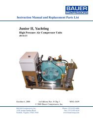
Parts supplied<br />
Unpack your <strong>ST60</strong> instrument and check that the following items are<br />
present:<br />
• Item 1, <strong>ST60</strong> <strong>Tridata</strong> instrument fitted with standard bezel for<br />
surface mounting.<br />
• Item 2, Fixing studs (2).<br />
• Item 3, Thumb nuts (2).<br />
• Item4, Gasket.<br />
• Item 5, Depth transducer.<br />
• Item 6, Speed transducer, plus bung (not illustrated).<br />
• Item 7, SeaTalk interconnection cable.<br />
• Item 8, Power cable.<br />
• Item 9, <strong>Instrument</strong> Cover.<br />
• Item 10, Owner’s <strong>Handbook</strong>. A Warranty document and fitting<br />
templates are included in this <strong>Handbook</strong>.<br />
• Item11, CueCard.<br />
Spare spade terminals are also provided, to re-terminate the transducer<br />
cable if it has to be cut to facilitate installation.<br />
Note: The above packing list is for an <strong>ST60</strong> <strong>Tridata</strong> system. Where an<br />
instrument is purchased separately, Speed and Depth transducers are<br />
not included.
Current<br />
depth<br />
depth<br />
Shallow Alarm<br />
Threshold<br />
Deep<br />
alarm threshold<br />
Anchor shallow<br />
alarm threshold<br />
Anchor deep<br />
alarm threshold<br />
Boat speed<br />
Maximum<br />
speed<br />
speed<br />
reset<br />
3s to Reset<br />
Average speed<br />
VMG to<br />
windward<br />
reset<br />
3s to Reset<br />
Log<br />
Trip<br />
Water<br />
temperature<br />
reset<br />
Start/Stop<br />
trip<br />
Count-up timer<br />
10 minute<br />
race start time<br />
reset<br />
Start/Stop<br />
5 minute<br />
race start timer<br />
reset<br />
Start/Stop<br />
reset<br />
3s to Reset<br />
reset<br />
3s to Reset<br />
reset<br />
3s to Reset<br />
reset<br />
3s to Reset<br />
x<br />
<strong>ST60</strong> <strong>Tridata</strong> <strong>Instrument</strong> Owner’s Manual<br />
1<br />
4<br />
2<br />
3<br />
6<br />
2<br />
3<br />
5<br />
7<br />
9<br />
8<br />
TRIDATA<br />
<strong>ST60</strong><br />
<strong>Tridata</strong><br />
<strong>Instrument</strong><br />
<strong>Owner's</strong><br />
<strong>Handbook</strong><br />
10<br />
11<br />
D4441-4
Chapter 1: Operation 1<br />
Chapter 1: Operation<br />
1.1 Getting started<br />
This handbook describes how to operate, maintain and install the<br />
Raymarine <strong>ST60</strong> <strong>Tridata</strong> instrument.<br />
CAUTION:Calibration requirement<br />
The <strong>ST60</strong> <strong>Tridata</strong> instrument is calibrated to factory (default)<br />
settings when first installed and must therefore be calibrated before<br />
use, in accordance with the procedures in Chapter 4, Calibration,to<br />
ensure optimum performance on your vessel.<br />
Do NOT use the instrument until the calibration procedures have<br />
been satisfactorily completed.<br />
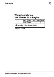
Displayed information<br />
The <strong>ST60</strong> <strong>Tridata</strong> instrument screen is divided into three separate areas,<br />
each of which displays a separate type of information, as shown in the<br />
following illustration.<br />
Depth<br />
Speed<br />
Trip, log, water<br />
temperature & timer<br />
Screen layout<br />
D4424-2<br />
1.2 Normal operation<br />
Use the flow charts in this Chapter to operate your <strong>ST60</strong> <strong>Tridata</strong><br />
instrument. Flow charts are provided for:<br />
• Usingthedepth key. This gives access to current depth information.<br />
On master instruments, thisalso gives accessto depthalarm threshold<br />
information, and allows you to set the alarm thresholds.<br />
• Usingthespeed key. This gives access to maximum speed, average<br />
speed and Velocity Made Good (VMG) to windward.
2 <strong>ST60</strong> <strong>Tridata</strong> <strong>Instrument</strong> Owner’s Manual<br />
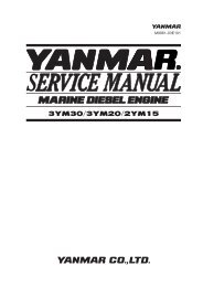
Depth<br />
• Usingthetrip key to gain access to log, trip, water temperature and<br />
timer information.<br />
All key presses are momentary unless otherwise stated.<br />
Use the depth key to select the required information, as shown in the<br />
Using the depth key illustration. The depth measurement units are either<br />
feet or metres, as selected during user calibration (see Chapter 4,<br />
Calibration).<br />
Current depth<br />
Shallow<br />
alarm threshold<br />
depth<br />
To enable/disable any alarm<br />
Press<br />
reset<br />
for 2 seconds<br />
(toggle action)<br />
depth<br />
Anchor deep<br />
alarm threshold<br />
To enter and exit alarm adjust mode<br />
depth<br />
Deep<br />
alarm threshold<br />
Press trip and reset together<br />
In adjust mode, use<br />
trip to decrease or reset to increase<br />
depth<br />
Anchor shallow<br />
alarm threshold<br />
depth<br />
Using the depth key D4413-1<br />
Current depth display<br />
The current depth screen shows the title DEPTH, the selected depth units<br />
and the depth measurement. It also shows a depth trend indicator, which<br />
is either an up arrow to show seabed rising or a down arrow to show<br />
seabed falling.
Chapter 1: Operation 3<br />
Speed<br />
If for any reason depth information is lost, the DEPTH title will flash once<br />
per second and the displayed depth value will be the last good reading.<br />
Depth alarm threshold displays<br />
The alarm threshold displays are available if the instrument is operating<br />
as a master. Each display is identified by the presence of an alarm symbol<br />
( )and either an up arrow for a shallow alarm or a down arrow for a deep<br />
alarm. The shallow and deep anchor alarms are identified by means of an<br />
additional anchor icon.<br />
You can enable and disable individual alarm thresholds by pressing the<br />
reset key for 2 seconds, while the relevant alarm threshold is displayed.<br />
Each alarm threshold is displayed for a nominal 7 seconds, and if no<br />
action is taken during that time, the display will timeout to the current<br />
depth display.<br />
Adjusting alarm thresholds<br />
To adjust the alarm threshold levels, press the trip and reset keys<br />
simultaneously to enter adjust mode, then use either the trip key (to<br />
decrease) or the reset key (to increase) the threshold value. When you<br />
have set the required value, press the trip and reset keys again, to save the<br />
alarm setting and exit the adjust mode.<br />
Note: Adjustment of the shallow alarm threshold can be disabled during<br />
calibration. When adjustment is disabled, you cannot enter adjust mode.<br />
Use the speed key to select the required information, as shown in the<br />
Using the speed key illustration. The speed measurement units are either<br />
knots (KTS), miles per hour (MPH) or kilometres per hour (KMH), as<br />
selected during user calibration (see Chapter 4, Calibration).<br />
The maximum speed, average speed and VMG to windward are each<br />
displayed for a nominal 7 seconds, and if no action is taken during that<br />
time, the display will timeout to the Boat speed display.<br />
Boat speed<br />
Shows the current speed and selected speed units.
4 <strong>ST60</strong> <strong>Tridata</strong> <strong>Instrument</strong> Owner’s Manual<br />
Boat speed<br />
speed<br />
speed<br />
Maximum<br />
speed<br />
VMG to<br />
windward<br />
speed<br />
Average speed<br />
speed<br />
Using the speed key<br />
D4414-1<br />
Maximum speed<br />
The screen shows the maximum speed attained since the last reset.<br />
The maximum speed value is reset automatically at power-up. If the<br />
instrument is operating as a master, the maximum speed can also be reset<br />
manually by pressing the reset key for 2 seconds.<br />
Average speed<br />
The screen shows the average speed since the last reset.<br />
The average speed value is reset automatically at power-up. If the<br />
instrument is operating as a master, the average speed can also be reset<br />
manually by pressing the reset key for 2 seconds.<br />
Velocity made good (to windward)<br />
Velocity made good (VMG) information is available if your instrument is<br />
part of a SeaTalk system to which a SeaTalk-compatible wind instrument<br />
is also connected.
Chapter 1: Operation 5<br />
Trip<br />
The trip key gives access to log, trip, water temperature and timer<br />
displays, as shown in the Using the trip key illustration.<br />
Water<br />
temperature<br />
trip<br />
Trip<br />
Count-up<br />
timer<br />
trip<br />
trip<br />
Log<br />
Race start<br />
timer 1<br />
trip<br />
Press<br />
trip<br />
Race start<br />
timer 2<br />
reset<br />
either momentarily<br />
to start timer, or for lap time (when running)<br />
or for 1 s to reset timer to start value.<br />
trip<br />
To enter/leave<br />
adjust mode, press<br />
To enter/leave<br />
adjust mode, press<br />
trip<br />
and<br />
reset<br />
trip<br />
and<br />
reset<br />
momentarily<br />
To set a different race start timer value, press<br />
momentarily<br />
trip<br />
reset<br />
Using the trip key<br />
to decrease the value<br />
to increase the value<br />
D4415-2<br />
Log<br />
The Log screen shows the total distance covered by the vessel since the<br />
instrument was fitted.
6 <strong>ST60</strong> <strong>Tridata</strong> <strong>Instrument</strong> Owner’s Manual<br />
Trip screen<br />
The trip screen shows the distance covered since the trip value was last<br />
reset.<br />
The trip value is reset automatically at power-up, and if the instrument is<br />
operating as a master, the trip value can also be reset manually by<br />
pressing the reset key for 3 seconds.<br />
Water temperature<br />
The water temperature is shown in either degrees Celsius (°C)or<br />
Fahrenheit (°F), as set during calibration (see Chapter 4, Calibration).<br />
Timers<br />
The count-up timer and to the two race-start timer times are either in<br />
seconds (S) or minutes (M), depending on the counter values.<br />
Refer to the Using the trip key flow diagram to display the required timer.<br />
Once you have done this, press the reset key to start the timer running.<br />
When a timer is running, the delimiter (i.e. ‘.’or ‘:’) flashes. For lap<br />
timing, press the reset key. To stop and reset a timer to the start value,<br />
hold down the reset key for 1 second.<br />
Once a timer is running, you can leave the timer page and select any other<br />
display. The counter will continue to run in the background.<br />
Race-start timers<br />
You can set each race-start timer to any whole-minute value from 1 to 15<br />
minutes.<br />
Note: When the instrument is first installed, the race-start timers are set<br />
to 4 and 5 minutes respectively.<br />
To set a race-start timer:<br />
1. Use the trip key as shown in the Using trip key flow diagram to select<br />
the required race-start timer.<br />
2. Simultaneously press the trip and reset keys to enter the race-start<br />
timer adjust mode.<br />
3. Use either the trip or reset key to set the required value.<br />
4. Simultaneously press the trip and reset keys to save the value and<br />
leave the race-start timer adjust mode.
Chapter 1: Operation 7<br />
1.3 Alarms<br />
If you are using one of the race-start timers and the timer buzzer is<br />
enabled, the buzzer will:<br />
• Double-beep every minute.<br />
• Beep three times at the start of the last 30 seconds.<br />
• Beep once for each of the last 10 seconds.<br />
• Beep for 2 seconds at zero.<br />
The timer buzzer is enabled or disabled as part of the calibration<br />
procedure (see Chapter 4, Calibration).<br />
Note: After a race-start timer has counted-down to zero, it will then start<br />
counting up.<br />
An alarm condition occurs if:<br />
• The depth is less than the SHALLOW or SHALLOW anchor threshold.<br />
• The depth is greater than the DEEP anchor threshold.<br />
• The depth crosses the DEEP threshold.<br />
An alarm condition is indicated by an alarm buzzer and a flashing alarm<br />
symbol ( ) on the display. SHALLOW or DEEP alarms are indicated by up<br />
and down arrows respectively, and for anchor alarms an anchor symbol<br />
( ) is displayed.<br />
When the instrument is operating as a master, you can check the alarm<br />
thresholds and if necessary set them up, as detailed under Normal<br />
operation - Depth. If an alarm is not enabled, the associated display<br />
shows an OFF legend.<br />
1.4 Display settings<br />
Illumination<br />
When the instrument is first powered up, the display illumination is set to<br />
its lowest (courtesy) level, to facilitate initial access to the keys.<br />
To adjust the level of display illumination:<br />
1. Hold down the depth key for approximately one second, to enter the<br />
illumination-adjust mode.<br />
2. There are four preset illumination levels. Use the depth keytocycle<br />
through these levels until you reach the level you want.
8 <strong>ST60</strong> <strong>Tridata</strong> <strong>Instrument</strong> Owner’s Manual<br />
3. Press any other key to leave the illumination-adjust mode.<br />
Note: The display will also return to normal operation 7 seconds after<br />
the last key press.<br />
Contrast<br />
To adjust the display contrast:<br />
1. Hold down the depth key for approximately two seconds, to enter the<br />
contrast-adjust mode.<br />
2. There are four preset contrast settings. Use the depth keytocycle<br />
through these settings until you achieve optimum display quality.<br />
3. Press any other key to leave the contrast-adjust mode.<br />
Note: The display will also return to normal operation 7 seconds after<br />
the last key press.<br />
1.5 Remote control<br />
When it is connected to SeaTalk, the <strong>ST60</strong> <strong>Tridata</strong> instrument can be<br />
controlled remotely with a SeaTalk Remote Keypad Unit. Remote<br />
control of an instrument is indicated by a REMOTE legend on the display,<br />
to indicate that the keypad has control.<br />
Details on how to use the remote control facility can be found in the<br />
SeaTalk Remote Keypad Owner’s <strong>Handbook</strong>.
Chapter 2: Maintenance and Faultfinding 9<br />
Chapter 2: Maintenance and Faultfinding<br />
2.1 Maintenance<br />
Servicing and safety<br />
• Raymarine equipment should be serviced only by authorised Raymarine<br />
service technicians. They will ensure that servicing procedures<br />
and replacement parts used will not affect performance. There are no<br />
user-serviceable parts in any Raymarine product.<br />
• Some products generate high voltages, and so never handle the<br />
cables/connectors when power is being applied to the equipment.<br />
• When powered up, all electrical equipment produces electromagnetic<br />
fields. These can cause adjacent pieces of electrical equipment<br />
to interact with one another, with a consequent adverse effect on operation.<br />
In order to minimise these effects and enable you to get the best<br />
possible performance from your Raymarine equipment, guidelines<br />
are given in the installation instructions, to enable you to ensure minimum<br />
interaction between different items of equipment, i.e. ensure<br />
optimum Electromagnetic Compatibility (EMC).<br />
• Always report any EMC-related problem to your nearest Raymarine<br />
dealer. We use such information to improve our quality standards.<br />
• In some installations, it may not be possible to prevent the equipment<br />
from being affected by external influences. In general this will not<br />
damage the equipment but it can lead to spurious resetting action, or<br />
momentarily may result in faulty operation.<br />
<strong>Instrument</strong><br />
Certain atmospheric conditions may cause condensation to form on the<br />
instrument window. This will not harm the instrument and can be cleared<br />
by increasing the illumination setting to Level 3.<br />
Periodically clean your <strong>ST60</strong> instrument with a soft damp cloth. Do NOT<br />
use chemical and abrasive materials to clean the instrument.<br />
Transducers<br />
Refer to the Installation and Maintenance instructions supplied with the<br />
transducers.
10 <strong>ST60</strong> <strong>Tridata</strong> <strong>Instrument</strong> Owner’s Manual<br />
Cabling<br />
2.2 Fault finding<br />
Examine all cables for chafing or other damage to the outer shield and,<br />
where necessary, replace and re-secure.<br />
Preliminary procedures<br />
Changes in the electronic environment may adversely affect the operation<br />
of your <strong>ST60</strong> equipment. Typical examples of such changes are:<br />
• Electrical equipment has recently been installed or moved aboard<br />
your vessel.<br />
• You are in the vicinity of another vesselor shore station emitting radio<br />
signals.<br />
If you appear to have a problem, first ensure that the EMC requirements<br />
(see Chapter 3, Installation) are still being met before further<br />
investigating the problem.<br />
Fixing faults<br />
All Raymarine products are subjected to comprehensive test and quality<br />
assurance programmes prior to packing and shipping. However, if a fault<br />
occurs, the following table may help to identify and rectify the problem.<br />
Fault Cause Remedy<br />
<strong>Instrument</strong> display blank. No power supply. Check power supply.<br />
Check SeaTalk cabling and connector<br />
security.<br />
Check fuse/circuit breaker.<br />
No speed or temperature<br />
information.<br />
Speed transducer<br />
cabling problem.<br />
Check cabling and security of<br />
transducer connections.<br />
No speed information.<br />
Speed transducer<br />
paddle wheel fouled<br />
Clean paddle wheel.<br />
See CAUTION below.<br />
No exchange of information<br />
between SeaTalk<br />
instruments<br />
SeaTalk cabling<br />
problem.<br />
Check the security of SeaTalk<br />
connectors.<br />
Disconnect instruments one by one, to<br />
isolate faulty unit
Chapter 2: Maintenance and Faultfinding 11<br />
Fault Cause Remedy<br />
Failure of group of<br />
instruments in SeaTalk<br />
chain.<br />
SeaTalk cabling or<br />
connector problem.<br />
Check the security of SeaTalk<br />
connections between functioning and<br />
non-functioning instruments.<br />
LAST flashes or dashes<br />
displayed continuously<br />
(depth greater than 3 feet).<br />
Depth transducer or<br />
connection problem.<br />
Check depth transducer cable and<br />
security of transducer connections.<br />
LAST flashes while under<br />
way.<br />
Aerated water<br />
Boat wake<br />
Prop wash etc<br />
Ensure readings stabilise when clear of<br />
disturbed water.<br />
CAUTION:<br />
If you need to remove the Speed transducer insert, have the<br />
transducer bung to hand and secure it in the transducer body<br />
immediately after the insert has been removed, to prevent excessive<br />
ingress of water.<br />
Technical support<br />
Raymarine provides a comprehensive customer support service, on the<br />
world wide web and by telephone help line. Please use either of these<br />
facilities if you are unable to rectify a problem.<br />
World wide web<br />
Please visit the Customer Support area of our web site at:<br />
www.raymarine.com<br />
As well as providing a comprehensive Frequently Asked Questions<br />
section and servicing information, it also gives e-mail access to the<br />
Raymarine Technical Support Department and a details of the locations<br />
of Raymarine agents, worldwide.<br />
Telephone help line<br />
If you do not have access to the world wide web, please call:<br />
1-800-539-5539, extension 2444 or<br />
(603) 881-5200 extension 2444
12 <strong>ST60</strong> <strong>Tridata</strong> <strong>Instrument</strong> Owner’s Manual<br />
Help us to help you<br />
When requesting service, please quote the following product<br />
information:<br />
• Equipment type.<br />
• Model number.<br />
• Serial number.<br />
• Software issue number.<br />
The Software issue number can be ascertained by means of the<br />
Intermediate Calibration facility, see Chapter 4, Calibration.
Chapter 3: Installation 13<br />
Chapter 3: Installation<br />
This chapter describes how to install the <strong>ST60</strong> <strong>Tridata</strong> instrument, and<br />
associated Speed and Depth transducers. The transducers are fitted in the<br />
hull of the vessel and connected to the rear of the instrument. The actual<br />
type of transducers depends on the type of hull in which they are to be<br />
installed.<br />
For advice, or further information regarding the installation of this<br />
equipment, please contact the Raymarine Product Support Department<br />
or your own National Distributor.<br />
3.1 Planning your installation<br />
Before starting the installation, spend some time considering the best<br />
positions for both transducer and instrument, such that the Site<br />
Requirements and the EMC Guidelines (below) are satisfied.<br />
Site requirements<br />
Transducers<br />
75 mm (2.94 in)<br />
diameter<br />
75 mm (2.94 in)<br />
diameter<br />
95 mm (3.75 in)<br />
Depth<br />
Speed<br />
100 mm<br />
(3.95 in)<br />
51 mm (2.0 in)<br />
diameter<br />
5 mm<br />
(0.19 in)<br />
51 mm (2.0 in)<br />
diameter<br />
14 mm<br />
(0.57 in)<br />
75 mm (2.94 in)<br />
diameter<br />
75 mm (2.94 in)<br />
diameter<br />
D4447-4<br />
The transducer types required for the various hull types are as follows:
14 <strong>ST60</strong> <strong>Tridata</strong> <strong>Instrument</strong> Owner’s Manual<br />
Hull material Speed transducer Depth transducer<br />
Glass reinforced<br />
plastic (GRP)<br />
M78712 Through hull plastic<br />
M78713 Through hull plastic or<br />
M78718 Retractable through hull<br />
Steel M78712 Through hull plastic M78713 Through hull plastic or<br />
M78718 Retractable through hull<br />
Aluminium M78712 Through hull plastic M78713 Through hull plastic or<br />
M78718 Retractable through hull<br />
Wood M78716 Through hull bronze M78714 Through hull bronze or<br />
M78719 Retractable through hull<br />
bronze<br />
Other transducer types are also available for specific requirements. For<br />
further details, contact your local Raymarine dealer.<br />
For accurate speed and depth readings the transducers should be sited<br />
within the clear water flow areas indicated by the shaded areas in the<br />
following diagram.<br />
Sailing vessel<br />
Planing power<br />
vessel<br />
Displacement power<br />
vessel<br />
Transducer siting D4349-1<br />
The transducers should also:<br />
• Be ahead of the propellers (by a minimum of 10% of the water line<br />
length).<br />
• Be at least 150 mm (6 in) away from the keel (ideally ahead of the<br />
keel if a sailing yacht).
Chapter 3: Installation 15<br />
• Be as near as possible to the centre line of the vessel.<br />
• Be clear of other through-hull fittings or projections.<br />
• Have sufficient clearance inside the hull to fit the nut.<br />
• Have 100 mm (4 in) of headroom to allow for withdrawal.<br />
In addition to the above requirements, the depth transducer must be<br />
mounted within 10 of the vertical, forward, aft and athwart ships.<br />
0<br />
10˚ maximum<br />
Maximum transducer angle<br />
D4350-3<br />
<strong>Instrument</strong><br />
CAUTION:<br />
The presence of moisture at the rear of the instrument could cause<br />
damage either by entering the instrument through the breathing<br />
hole or by coming into contact with the electrical connectors.<br />
<strong>ST60</strong> instruments can be fitted either above or below deck, provided the<br />
rear of the instrument is sited where it is protected from contact with water.<br />
Each instrument must also be positioned where:<br />
• It is easily read by the helmsman<br />
• It is protected against physical damage<br />
• It is at least 230 mm (9 in) from a compass<br />
• It is at least 500 mm (20 in) from radio receiving equipment<br />
• There is reasonable rear access for installation and servicing
16 <strong>ST60</strong> <strong>Tridata</strong> <strong>Instrument</strong> Owner’s Manual<br />
With standard<br />
bezel<br />
90mm (3.54in)<br />
diameter<br />
115mm (4.53in)<br />
110mm (4.33in)<br />
24mm<br />
(0.95in)<br />
15mm<br />
(0.6in)<br />
With low<br />
profile bezel<br />
90mm (3.54in)<br />
diameter<br />
123mm (4.85in)<br />
123mm (4.85in)<br />
<strong>ST60</strong> instrument dimensions<br />
6.2mm<br />
(0.25in)<br />
35mm<br />
(1.4in)<br />
D5785-1<br />
EMC Installation Guidelines<br />
All Raymarine equipment and accessories are designed to the best<br />
industry standards for use in the recreational marine environment.<br />
Their design and manufacture conforms to the appropriate<br />
Electromagnetic Compatibility (EMC) standards, but correct installation<br />
is required to ensure that performance is not compromised. Although<br />
every effort has been taken to ensure that they will perform under all<br />
conditions, it is important to understand what factors could affect the<br />
operation of the product.<br />
The guidelines given here describe the conditions for optimum EMC<br />
performance, but it is recognized that it may not be possible to meet all of<br />
these conditions in all situations. To ensure the best possible conditions<br />
for EMC performance within the constraints imposed by any location,<br />
always ensure the maximum separation possible between different items<br />
of electrical equipment.
Chapter 3: Installation 17<br />
For optimum EMC performance, it is recommended that wherever<br />
possible:<br />
• Raymarine equipment and cables connected to it are:<br />
• At least 3 ft (1 m) from any equipment transmitting or cables carrying<br />
radio signals e.g. VHF radios, cables and antennas. In the<br />
case of SSB radios, the distance should be increased to 7 ft (2 m).<br />
• More than 7 ft (2 m) from the path of a radar beam. A radar beam<br />
can normally be assumed to spread 20 degrees above and below<br />
the radiating element.<br />
• The equipment is supplied from a separate battery from that used for<br />
engine start. Voltage drops below 10 V in the power supply to our<br />
products, and starter motor transients, can cause the equipment to<br />
reset. This will not damage the equipment, but may cause the loss of<br />
some information and may change the operating mode.<br />
• Raymarine specified cables are used. Cutting and rejoining these<br />
cables can compromise EMC performance and must be avoided<br />
unless doing so is detailed in the installation manual.<br />
• If a suppression ferrite is attached to a cable, this ferrite should not be<br />
removed. If the ferrite needs to be removed during installation it must<br />
be reassembled in the same position.<br />
Suppression Ferrites<br />
The following illustration shows typical cable suppression ferrites used<br />
with Raymarine equipment. Always use the ferrites supplied by<br />
Raymarine.<br />
D3548-2<br />
Connections to Other Equipment<br />
If your Raymarine equipment is to be connected to other equipment using<br />
a cable not supplied by Raymarine, a suppression ferrite MUST always<br />
be attached to the cable near the Raymarine unit.
18 <strong>ST60</strong> <strong>Tridata</strong> <strong>Instrument</strong> Owner’s Manual<br />
3.2 Procedures<br />
As it is not possible to describe procedures for all possible installation<br />
scenarios, the procedures given here describe the broad requirements for<br />
installing the Speed and Depth transducers and the <strong>ST60</strong> <strong>Tridata</strong><br />
instrument. Adapt these procedures as appropriate, to suit your<br />
individual requirement.<br />
CAUTION:<br />
Where it is necessary to cut holes (e.g. for cable routing and<br />
instrument mounting), ensure that these will not cause a hazard by<br />
weakening critical parts of the vessel’s structure.<br />
Unpacking<br />
Unpack your <strong>ST60</strong> equipment and check that the items described in<br />
Introduction are present.<br />
Each <strong>ST60</strong> instrument is supplied with a standard bezel for surface<br />
mounting. Optional mounting kits are available for flush mounting and<br />
bracket mounting the instrument. If you have ordered the flush mounting<br />
option a low-profile bezel and four fixing screws are also provided.<br />
Fitting the instrument<br />
The <strong>ST60</strong> <strong>Tridata</strong> instrument can be installed using one of a number of<br />
different mounting options:<br />
• Surface mounting. Gives a profile of approximately 24 mm.<br />
• Flush mounting. Gives a profile of approximately 6 mm.<br />
• Bracket mounting.<br />
The <strong>ST60</strong> instruments can also be mounted behind a panel with just the<br />
instrument dial and keys visible.<br />
Surface mounting<br />
To surface mount your <strong>ST60</strong> instrument (see the Surface mounting<br />
illustration):<br />
1. Ensure that:<br />
• The selected location is clean, smooth and flat.<br />
• There is sufficient space behind the selected location to accommodate<br />
the rear of the instrument and connectors.
Chapter 3: Installation 19<br />
Surface mounting<br />
4 1 2 1 3 5 2 5<br />
D4343-2<br />
2. Apply the surface mount template (supplied at the rear of this handbook)<br />
to the selected location and mark the centres for the fixing studs<br />
(1) and the aperture (3) that will take the rear casing of the instrument.<br />
3. Drill out the two 5 mm fixing stud clearance holes (2).<br />
4. Cut out the clearance hole (3) then remove the template.<br />
5. Peel off the protective sheet from the self-adhesive gasket (4) then<br />
stick the gasket into position on the rear of the instrument.<br />
6. Screw the two fixing studs into the threaded sockets on the rear of the<br />
instrument.<br />
7. Mount the assembled instrument, studs, bezel and gasket into the<br />
panel. Secure from behind with the thumb nuts (5).<br />
Flush mounting<br />
The Flush Mounting Kit uses a low-profile bezel to reduce the fitted<br />
profile of the instrument, to approximately 6 mm above the panel fascia.
20 <strong>ST60</strong> <strong>Tridata</strong> <strong>Instrument</strong> Owner’s Manual<br />
Fitting the low-profile bezel<br />
In order to flush-mount your <strong>ST60</strong> instrument, you must first replace the<br />
standard bezel with the low-profile bezel as follows:<br />
1. Hold the instrument in both hands with the display towards you.<br />
D4537-2<br />
2. Using both thumbs, gently press an upper corner of the instrument<br />
from the bezel, then remove the bezel from the instrument. Retain the<br />
rubber keypad which is released when the bezel is removed.<br />
3. Referring to the Fitting the low-profile bezel illustration, place the<br />
instrument face upwards on a flat surface and place the rubber keypad<br />
(7) in position around the display window (i.e. so that each key outline<br />
is located over its associated key on the instrument).<br />
4. Snap the low-profile bezel (8) in position over the instrument, so that<br />
the rubber keys are correctly located in the holes on the bezel.<br />
CAUTION:<br />
It is essential that only screws of the correct size are used to secure the<br />
instrument to the bezel. Failure to observe this caution could result<br />
in damage to both the instrument and the bezel.<br />
5. Using the four, self-tapping screws (9) provided, secure the instrument<br />
and bezel together. Fit the screws from the rear of the instrument<br />
and tighten them sufficiently to secure the instrument and bezel<br />
together. DO NOT OVERTIGHTEN.
Chapter 3: Installation 21<br />
Fitting the low profile bezel<br />
8 7<br />
9<br />
D4362-2<br />
Flush mounting procedure<br />
Flush mount your instrument (see the Flush mounting illustration) as<br />
follows:<br />
1. Assemble the <strong>ST60</strong> instrument and low-profile bezel as described<br />
under Fitting the low-profile bezel.<br />
2. Ensure that:<br />
• The panel on which you intend to mount the instrument is<br />
between 3 mm and 20 mm thickness.<br />
• The selected location is clean, smooth and flat.<br />
• There is sufficient space behind the selected location to accommodate<br />
the rear of the instrument and connectors.<br />
3. Apply the flush mount template (supplied at the rear of this handbook)<br />
to the selected location and mark out the aperture into which<br />
the assembled instrument and bezel will sit.<br />
4. Cut out the aperture (3) for the assembled instrument and bezel and<br />
remove the template.<br />
5. Peel off the protective sheet from the self-adhesive gasket (4) then<br />
stick the gasket into position on the rear of the bezel.
22 <strong>ST60</strong> <strong>Tridata</strong> <strong>Instrument</strong> Owner’s Manual<br />
1 3 1<br />
5 6 5<br />
4<br />
Flush mounting<br />
D5462-1<br />
6. Screw the two fixing studs (1) into the threaded sockets on the rear of<br />
the instrument.<br />
7. Mount the assembled instrument, studs, bezel and gasket into the<br />
panel.<br />
8. Locate the flush mount bracket (6) onto the fixing studs and secure<br />
the assembly to the panel with the thumb-nuts (5).<br />
Bracket mounting<br />
A Control Unit Mounting Bracket (Part No. E25009) enables you to<br />
mount your <strong>ST60</strong> instrument in locations where other forms of mounting<br />
are impractical. Although this provides a useful alternative method for<br />
securing your instrument, it is only suitable for use in positions where the<br />
instrument will not be exposed to water.<br />
To bracket mount your <strong>ST60</strong> instrument, do so in accordance with the<br />
Control Unit Mounting Bracket Instruction Sheet.
Chapter 3: Installation 23<br />
Fitting transducer<br />
The <strong>ST60</strong> <strong>Tridata</strong> instrument is supplied, with appropriate through-hull<br />
Speed and Depth transducers.<br />
Each transducer is supplied with detailed instructions for installation and<br />
maintenance. Before attempting to install a transducer, read these<br />
instructions and the Site requirements for transducers described in this<br />
Chapter.<br />
Once you are satisfied you can meet all the installation requirements,<br />
install the transducer in accordance with the accompanying installation<br />
instructions.<br />
Running transducer cable<br />
Each transducer type has a 14 m (45 ft) cable fitted with spade terminals<br />
for connection to the <strong>ST60</strong> <strong>Tridata</strong> instrument. The manner in which you<br />
run the cable will depend on the locations of the transducers and<br />
instrument. The following guidelines are provided:<br />
• If the cable has to be fed through the deck, always use a proprietary<br />
deck gland.<br />
• Where cables are fed through holes, always use grommets to prevent<br />
chafing.<br />
• Secure long cable runs so they do not present a hazard.<br />
• Do not route the cable through bilges.<br />
• Wherever possible, route the cable away from fluorescent lights,<br />
engines, radio transmitting equipment, as these may cause interference.<br />
• The transducer cables are fitted with spade connectors for direct connection<br />
to the rear of the instrument. However, it may be necessary to<br />
remove these to facilitate installation, e.g. if a cable has to be routed<br />
through narrow apertures. Extra spade connectors are provided, to<br />
replace any that are removed when running transducer cables. When<br />
fitting spade connectors, prepare the cable as at (a) in the following<br />
illustration, then fold back the wire strands and insert into the spade<br />
connector as at (b). Ensure the wire strands do not extend beyond the<br />
rear of the spade connector insulation, then crimp the connector to the<br />
wire.
24 <strong>ST60</strong> <strong>Tridata</strong> <strong>Instrument</strong> Owner’s Manual<br />
50 mm<br />
6 mm<br />
(a)<br />
Observing the above guidelines, run the transducer cables to the <strong>ST60</strong><br />
<strong>Tridata</strong> instrument.<br />
Connecting the instrument<br />
Types of connection<br />
The <strong>ST60</strong> <strong>Tridata</strong> instrument, can be connected:<br />
• As a stand-alone, master instrument connected directly to a Speed<br />
and/or Depth transducer.<br />
• As a SeaTalk repeater.<br />
• To fulfil both repeater and master roles by being connected both to the<br />
transducer and to SeaTalk.<br />
If instruments are connected to SeaTalk, no separate power connection is<br />
necessary. Where a SeaTalk system includes an autopilot, the power for<br />
the system is provided by the autopilot.<br />
A range of Raymarine SeaTalk extension cables is available to connect<br />
separated instruments. These cables are supplied with a SeaTalk<br />
connector fitted to each end. A junction box can be used to join cables.<br />
Signal connections<br />
(b) 3 mm<br />
D4467-6<br />
Make the necessary connections to your <strong>ST60</strong> instrument (see the<br />
Connection to <strong>ST60</strong> <strong>Tridata</strong> instrument illustration).
DEPTH<br />
Chapter 3: Installation 25<br />
SeaTalk cable<br />
SeaTalk cable<br />
SPEED<br />
Cable from Depth transducer<br />
Cable from Speed transducer<br />
Black<br />
Blue<br />
Screen<br />
Brown<br />
White<br />
Screen<br />
Green<br />
Red<br />
Connections to <strong>ST60</strong> <strong>Tridata</strong> instrument<br />
D4423-1<br />
Power supply connections<br />
SeaTalk systems<br />
CAUTION:<br />
When instruments are connected to SeaTalk, ensure that the power<br />
supply for the SeaTalk 12 V line is protected by a 5 A fuse.<br />
Systems with a large number of instruments on the SeaTalk bus may<br />
require connections to the power supply from each end of the system<br />
(‘ring-main’ style), to maintain sufficient voltage throughout the system.<br />
This requirement depends on the total length of the cable run and the total<br />
number of instruments in the system, as follows:<br />
Cable run No. of instruments Power connections<br />
Up to 10 m<br />
Up to 20 m<br />
13 maximum<br />
26 maximum<br />
7 maximum<br />
13 maximum<br />
1<br />
2<br />
1<br />
2
26 <strong>ST60</strong> <strong>Tridata</strong> <strong>Instrument</strong> Owner’s Manual<br />
Red<br />
5 A fused,<br />
12 V dc supply<br />
(typically provided<br />
by autopilot)<br />
Screen<br />
1 2 3 4<br />
Red<br />
<strong>Instrument</strong>s<br />
5 to 16<br />
Screen<br />
20<br />
19<br />
18<br />
17<br />
SeaTalk power connections<br />
D4311-1<br />
Stand alone instruments<br />
Stand-alone instruments are not connected to SeaTalk and therefore need<br />
to be connected to an alternative 12 V power source. Power cables are<br />
available in 2 m and 9 m lengths.<br />
To fit a power cable:<br />
1. Ensure the intended power source is switched off. If you are using a<br />
12 V battery, ensure the power cable is not connected to the battery.<br />
2. Run the power cable from the instrument to a suitable 12 V dc power<br />
source.<br />
3. If the cable has not already been trimmed at the power supply end:<br />
• Cut the cable to length and trim back an appropriate amount of the<br />
outer sheath.<br />
• Cut back and insulate the yellow wire.<br />
4. Connect the screen to the power supply 0 V terminal.<br />
5. Connect the red wire via a 3 A over-current circuit breaker to the<br />
power supply +12 V terminal.
Calibration 27<br />
Chapter 4: Calibration<br />
4.1 Introduction<br />
The <strong>ST60</strong> <strong>Tridata</strong> instrument is set up with factory-programmed default<br />
settings, so in order to optimise the performance of the instrument on<br />
board a particular vessel, the procedures in this Chapter must be carried<br />
out immediately after the completion of installation and before the<br />
equipment is used for navigational purposes.<br />
Where practicable, the calibration procedures are presented<br />
diagrammatically to show the sequence of key presses and the resulting<br />
displays. Adjustment instructions are given as applicable.<br />
Speed readings<br />
One of the reasons for calibration is to ensure that the speed readings<br />
displayed at the instrument are a true indication of the actual speed of the<br />
vessel.<br />
In User calibration - Speed, you can:<br />
• Automatically set the displayed speed reading to be the same as the<br />
Speed Over Ground (SOG) (if SOG data is available).<br />
• Manually apply a calibration factor, to set the displayed speed to the<br />
required value.<br />
If neither of the above methods are suitable, you can carry out a speed<br />
calibration run over a measured distance, to enable the instrument to<br />
calculate the correct calibration factor. This is described as part of<br />
Intermediate calibration.<br />
EMC conformance<br />
Always check the installation before going to sea to make sure that it is<br />
not affected by radio transmissions, engine starting etc.<br />
4.2 User calibration<br />
The User calibration procedures enable you to:<br />
• Set the required units for depth readings.<br />
• Set the offset for depth readings, i.e. determine whether depth readings<br />
are from the keel of the vessel or from the water line.
28 <strong>ST60</strong> <strong>Tridata</strong> <strong>Instrument</strong> Owner’s Manual<br />
• Lock the shallow alarm.<br />
• Set the required units for speed readings.<br />
• Set the speed resolution.<br />
• Select the log distance units<br />
• Either calibrate the speed reading to Speed Over Ground (SOG) or<br />
manually apply a calibration factor, to obtain correct speed through<br />
the water.<br />
• Select temperature units.<br />
• Calibrate for correct temperature readings.<br />
• Set timer alarm buzzer on or off.<br />
Separate routines are provided for the User calibration of the depth and<br />
speed functions. To carry out either of these routines:<br />
1. Power up the <strong>ST60</strong> <strong>Tridata</strong> instrument.<br />
To start User calibration<br />
hold down<br />
depth and speed<br />
for approximately 2 seconds<br />
User calibration<br />
entry screen<br />
press either<br />
depth<br />
see User calibration - depth illustration<br />
or<br />
speed<br />
see User calibration - speed illustration<br />
Starting User calibration D4416-1<br />
2. Press the depth and speed keys for approximately 2 seconds so that<br />
the User calibration entry screen is displayed.<br />
3. Carry out the User calibration procedures for Depth and Speed.
Calibration 29<br />
Depth<br />
To calibrate the depth functions:<br />
1. With the User calibration entry screen displayed, press the depth key.<br />
2. Referring to the User calibration - depth illustration, carry out the calibration<br />
procedure. Use the depth keytocyclefromscreentoscreen<br />
and the trip and reset keys to set the required values at each screen.<br />
Depth units<br />
You can set either FEET or METRES.<br />
Set depth<br />
units<br />
From User calibration<br />
start screen<br />
depth<br />
depth<br />
Set depth<br />
offset<br />
Shallow<br />
alarm lock<br />
User calibration - depth<br />
Depth offset<br />
depth<br />
D4417-1<br />
WARNING:<br />
The use of incorrect offset values could result in misleading<br />
depth information being displayed with a consequent risk<br />
of running aground.<br />
Depths are measured from the transducer to the sea bed. However, you<br />
can use the depth offset screen to apply offsets to this distance, so that the<br />
displayed depth reading represents either the depth from the keel or the
30 <strong>ST60</strong> <strong>Tridata</strong> <strong>Instrument</strong> Owner’s Manual<br />
depth from the water line. In order to do this, you need to know the<br />
vertical separation between the transducer position and:<br />
• The bottom of the keel.<br />
• The water line.<br />
Use the trip (decrement) and reset (increment) keys to set the required<br />
offset value:<br />
• If you want to display the depth reading from the transducer, set a<br />
value of 0.0.<br />
• If you want to apply a water line offset, adjust the displayed reading<br />
until the appropriate positive offset value is shown.<br />
• If you want to apply a keel offset, adjust the displayed reading until<br />
the appropriate negative offset value is shown.<br />
+ve offset<br />
values<br />
Offset value<br />
of 0.0<br />
-ve offset<br />
values<br />
Depth offsets<br />
D4352-2<br />
Shallow alarm lock<br />
When set to on, prevents alteration to the shallow depth alarm threshold.
Calibration 31<br />
Speed<br />
To calibrate the speed functions:<br />
1. With the User calibration entry screen displayed, press the speed key.<br />
2. Referring to the User calibration - speed illustration, carry out the<br />
calibration procedure. Use the speed key to cycle from screen to<br />
screen and the trip and reset keys to set the required values at each<br />
screen (except Adjust to SOG display).<br />
Set speed units<br />
Select either KTS (knots), MPH (miles per hour) or KMH (kilometres per<br />
hour), as required.<br />
Set speed resolution<br />
Select resolution of either 0.01 or 0.1 as required.<br />
Set log units<br />
Select either NM (nautical miles), SM (statute miles) or KM (kilometres),<br />
as required.<br />
Setting the correct speed<br />
Set the displayed (current) speed using one of the following methods:<br />
• Use the Adjust to Speed Over Ground (SOG) screen to automatically<br />
set the current speed to SOG (if available from SeaTalk). You must be<br />
running in slack tide conditions to successfully use this method.<br />
• Manually apply a calibration factor by means of the Cal factor adjust<br />
screen, to set the displayed speed value to your best estimate of the<br />
vessel’s speed.
32 <strong>ST60</strong> <strong>Tridata</strong> <strong>Instrument</strong> Owner’s Manual<br />
From User calibration<br />
start screen<br />
Set speed<br />
units<br />
Set timer alarm<br />
speed<br />
speed<br />
speed<br />
Temperature<br />
calibration<br />
Set speed<br />
resolution<br />
speed<br />
Set log<br />
units<br />
speed<br />
Setting the correct speed<br />
Adjust<br />
to SOG<br />
Set temperature<br />
units<br />
speed<br />
If SOG<br />
available<br />
from<br />
SeaTalk<br />
speed<br />
trip<br />
&<br />
reset<br />
If SOG<br />
NOT<br />
available<br />
speed<br />
User calibration - speed<br />
Cal<br />
Factor<br />
Adjust<br />
D4418-1
Calibration 33<br />
Adjust to SOG<br />
The Adjust to SOG screen is displayed only if SOG data is available from<br />
SeaTalk. The current SOG is displayed in the bottom section of the<br />
display (SG12.8 in the illustration), and the currentspeed registered by the<br />
instrument, as large figures in the middle section of the display (12.3 in<br />
the illustration).<br />
It is recommended that, if you are running in slack tide conditions, you<br />
press the reset key for 3 seconds, to accept the SOG as the current speed.<br />
If you do not wish to accept SOG as the current speed, press the trip and<br />
reset keys together to select the Cal factor adjust display.<br />
Cal factor adjust<br />
The Cal factor adjust screen enables you to manually adjust the<br />
calibration factor. It shows the current calibration factor in the bottom<br />
section of the display (CF 1.00 in the illustration), and the current speed as<br />
large figures (12.3 in the illustration).<br />
Use the trip or reset key to adjust the calibration factor so that the current<br />
speed is the speed through the water.<br />
If SOG data is available from SeaTalk, you can turn to the Adjust to SOG<br />
screen by pressing the trip and reset keys.<br />
Note: If neither of the above methods gives satisfactory results, carry out<br />
the Speed calibration procedure (part of Intermediate calibration).<br />
Set temperature units<br />
Select either °C or °F, as required.<br />
Temperature calibration<br />
Set the display to show the current water temperature.<br />
Timer alarm buzzer<br />
Switches the count-up and race-start timer audible alarm on the <strong>ST60</strong><br />
<strong>Tridata</strong> instrument being calibrated, on and off.<br />
Leaving User calibration<br />
Hold down the depth and speed keys for 2 seconds, to save your settings,<br />
exit User calibration and resume normal operation.
34 <strong>ST60</strong> <strong>Tridata</strong> <strong>Instrument</strong> Owner’s Manual<br />
4.3 Intermediate calibration<br />
Intermediate calibration enables you to:<br />
• Check the instrument software version.<br />
• Check the instrument status - either YES (master)) or NO (repeater).<br />
You can also change the depth status, as required. This feature is particularly<br />
useful in preventing interference when using another product<br />
(e.g. a fishfinder) that operates at 200 kHz.<br />
• Carry out a calibration run over a measured distance to ensure accurate<br />
speed readings.<br />
To start Intermediate calibration, hold down the depth and speed keys<br />
for approximately 4 seconds (see Intermediate calibration flow chart).<br />
To set the instrument status:<br />
1. Press the depth key to select the <strong>Instrument</strong> status screen.<br />
2. Press the trip and reset keys simultaneously to enter the depth adjust<br />
mode, then press either trip or reset to set the required status, i.e.<br />
either YES (for master operation) or NO (for repeater operation).<br />
Note: You must not allocate more than one master depth instrument in<br />
any system.<br />
3. Press the trip and reset keys simultaneously again, to leave the adjust<br />
mode.
Calibration 35<br />
depth<br />
speed<br />
Software<br />
version<br />
<strong>Instrument</strong><br />
status<br />
depth<br />
(or NO for repeater)<br />
(or NO for repeater)<br />
depth<br />
Carry out speed calibration<br />
as detailed in<br />
Speed calibration - sheets 1 & 2<br />
depth<br />
Intermediate calibration<br />
D4419-1<br />
Speed calibration<br />
The speed calibration procedure involves carrying out two runs over a<br />
measured distance, to enable a calibration factor to be determined and<br />
applied to your <strong>ST60</strong> <strong>Tridata</strong> instrument, to ensure optimum accuracy.<br />
Each calibration run comprises outward and return legs, to minimise the<br />
affect of tidal drift when the calibration factor is determined.
36 <strong>ST60</strong> <strong>Tridata</strong> <strong>Instrument</strong> Owner’s Manual<br />
Note: It is recommended that the speed calibration procedure is carried<br />
out in conditions of minimum tidal drift.<br />
To carry out a speed calibration, start the Intermediate calibration<br />
procedure and use the speed key to proceed to the Calibration run length<br />
screen (see sheet 1 of the Speed calibration flow chart). Proceed with the<br />
speed calibration as follows:<br />
1. With the Calibration Run Length screen displayed, press the trip and<br />
reset keys together to enter adjust mode. In this mode, the displayed<br />
run length flashes on and off.<br />
2. Set the length of the intended calibration run, using either the trip key<br />
to decrement or the reset key to increment the run length value. You<br />
can set any value between 0.25 and 2.50.<br />
3. Press trip and reset keys together to commence the speed calibration.<br />
The Cal status screen is displayed. The text at the bottom of the screen<br />
alternates between Strt 1 and the calibration factor (CF) currently<br />
applied.<br />
4. Start first outward leg of the calibration run and as you pass the start<br />
point, press the speed key, so that the text out shows at the bottom of<br />
the screen. As the calibration run proceeds, the displayed value will<br />
increment.<br />
5. At the end of the measured distance on the outward leg, press the<br />
speed key again so that:<br />
• The text rEtrn is flashing at the bottom of the screen.<br />
• The displayed distance freezes. Note that this value will not be the<br />
same as the measured distance due to errors introduced by tidal<br />
flow.<br />
6. Turn the vessel round, start the return leg and as you do so, press the<br />
speed key so the rEtrn legend stops flashing and the displayed value<br />
increments.<br />
7. At the end of the return leg, press the speed key to end the calibration<br />
run. At this point:<br />
• The text Strt 2 alternating with the new calibration factor is displayed<br />
at the bottom of the screen.<br />
• The displayed distance freezes. This value should be very close to<br />
the actual (measured) distance of the calibration run.<br />
8. Press the depth and speed keys together, to store the new calibration<br />
factor.
Calibration 37<br />
from Intermediate calibration<br />
(<strong>Instrument</strong> status display)<br />
Calibration<br />
run length<br />
trip<br />
Use<br />
either<br />
reset<br />
trip<br />
and<br />
reset<br />
to set length<br />
of calibration run<br />
trip<br />
and<br />
reset<br />
At the start of the<br />
outward cal run<br />
press<br />
speed<br />
Carry out the<br />
outward leg of<br />
the first cal run<br />
Alternating<br />
Press<br />
speed<br />
At the end<br />
of the<br />
outward<br />
cal run<br />
Carry out the<br />
return leg of<br />
the first cal run<br />
At the start of<br />
the return cal<br />
run press<br />
speed<br />
Press<br />
speed<br />
At the end<br />
of the return<br />
cal run<br />
To store the calibration factor, press<br />
and<br />
depth speed<br />
speed<br />
Carry out second cal run<br />
as described on sheet 2<br />
Alternating<br />
Speed calibration - sheet 1 D4420-1
38 <strong>ST60</strong> <strong>Tridata</strong> <strong>Instrument</strong> Owner’s Manual<br />
from Speed<br />
calibration - sheet 1<br />
At the start of the<br />
outward cal run<br />
press<br />
speed<br />
Carry out the<br />
outward leg of<br />
the second<br />
cal run<br />
At the end of the<br />
outward cal run<br />
press<br />
speed<br />
Carry out the<br />
return leg of<br />
the second<br />
cal run<br />
At the start of<br />
the return cal<br />
run press<br />
speed<br />
At the end<br />
of the return<br />
cal run<br />
press<br />
speed<br />
Press<br />
depth and<br />
speed<br />
Press<br />
depth<br />
Alternating<br />
to store cal factor<br />
to return to<br />
<strong>Instrument</strong> status display<br />
(Intermediate calibration)<br />
Speed calibration - sheet 2<br />
D4421-1<br />
9. Carry out a second calibration run (see sheet 2 of the Speed calibration<br />
flow chart), using the procedure described above in steps 4 to 8.<br />
Note: At the end of this second run, the text End alternating with the new<br />
calibration factor is displayed at the bottom of the screen.<br />
10. Press the speed key to leave distance calibration and return to the<br />
<strong>Instrument</strong> status screen.
Calibration 39<br />
Leaving Intermediate calibration<br />
Hold down the depth and speed keys for 2 seconds, to save your settings,<br />
exit Intermediate calibration and resume normal operation.<br />
4.4 Dealer calibration<br />
The Dealer calibration procedures enable the following parameters to be<br />
set:<br />
• User calibration on/off.<br />
• Speed response.<br />
• Depth response.<br />
• Boat show mode on/off.<br />
Dealer calibration also gives access to the Factory defaults screen. This<br />
enables you to re-apply the factory settings if you want to reset the<br />
instrument to a known operating condition.<br />
To commence Dealer calibration, hold down the depth and speed keys<br />
together for approximately 12 seconds, to select the Dealer calibration<br />
entry page (see Dealer calibration diagram). Then press the trip and<br />
reset keys together, to enter the calibration screen sequence.<br />
Use the depth key to move from screen to screen and the trip or the rest<br />
key to set the required values at each screen.<br />
User calibration on/off<br />
Press either the trip or reset key to toggle the User calibration on or off as<br />
required. With off selected, User calibration and Intermediate calibration<br />
are both disabled.<br />
Response settings<br />
The response values for both SPEED and DEPTH determine the frequency<br />
at which information is updated. A low number provides a smooth<br />
response and a high number a much livelier update.<br />
Use the trip (decrement) and reset (increment) keys to set the required<br />
value. Response values are from 1 to 15.
40 <strong>ST60</strong> <strong>Tridata</strong> <strong>Instrument</strong> Owner’s Manual<br />
Hold down<br />
depth<br />
and<br />
speed<br />
for approximately 12 seconds<br />
trip<br />
and<br />
reset<br />
Calibration<br />
on/off<br />
Speed<br />
response<br />
depth<br />
depth<br />
Factory<br />
defaults<br />
At each screen use<br />
either<br />
trip<br />
or<br />
reset<br />
depth<br />
to set the required values<br />
depth<br />
Depth response<br />
Boat show mode<br />
depth<br />
Dealer calibration<br />
D4422-1
Calibration 41<br />
Boat show mode<br />
CAUTION:<br />
Do NOT enable this mode. It must only be used for demonstration<br />
purposes.<br />
Ensure that the Boatshow Mode Use is set to OFF. If necessary, use the<br />
trip or reset key to achieve this.<br />
Factory defaults<br />
You can use this screen to reset the operating parameters to the factory<br />
default values. If you want to apply the factory defaults, ensure the<br />
display shows YES, but if you want to retain the values you have set up,<br />
ensure that the display shows NO.Usethetrip and reset keys to make the<br />
required selection.<br />
The values you have selected will be applied when you exit this screen.<br />
Leaving Dealer calibration<br />
Hold down the depth and speed keys for 2 seconds to save your settings,<br />
exit Dealer calibration and resume normal operation.
42 <strong>ST60</strong> <strong>Tridata</strong> <strong>Instrument</strong> Owner’s Manual
<strong>ST60</strong> Surface Mount Template<br />
TOP<br />
Drill 5mm (3/16in) diameter<br />
Machine hole<br />
90mm (3.54in)<br />
diameter<br />
Shaded areas to be removed<br />
Drill 5mm (3/16in) diameter<br />
D4436-1
<strong>ST60</strong> Flush Mount Template<br />
TOP<br />
4 holes<br />
6 mm diameter<br />
Shaded area to be removed<br />
114 mm<br />
109 mm<br />
D4437-1