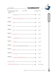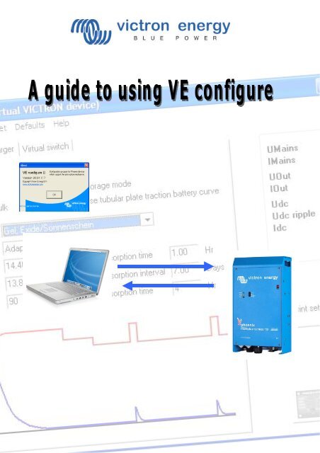
A guide to VE configure - Zanshin
A guide to VE configure - Zanshin
A guide to VE configure - Zanshin

Create successful ePaper yourself
Turn your PDF publications into a flip-book with our unique Google optimized e-Paper software.
Connecting your Victron product <strong>to</strong> a computer with <strong>VE</strong> Configure<br />
It is necessary <strong>to</strong> know several things before connecting your Victron product <strong>to</strong> a computer.<br />
• Phoenix Chargers, Phoenix Multi (including Compact) and larger Phoenix Inverters are all compatible<br />
with <strong>VE</strong> <strong>configure</strong>. All other models are not.<br />
• <strong>VE</strong> Configure 1 works with software<br />
1. 14xx100.HEX up <strong>to</strong> 14xx118.HEX (Phoenix chargers)<br />
2. All 15xxxxxx.HEX (Phoenix Multis/ Inverters)<br />
3. 17xx100>HEX up <strong>to</strong> 17xx129.HEX (Phoenix Multis/ Inverters)<br />
• <strong>VE</strong> Configure 2 is compatible with newer software versions.<br />
• You can find the software version number on the on the white sticker on the microprocessor on the<br />
controller PCB<br />
You can use converter MK1b (or latterly MK2b) <strong>to</strong> connect the UTP cable (same as the remote control cable)<br />
<strong>to</strong> an available serial COM port on your computer.<br />
Although the <strong>VE</strong> Configure program still supports MK1b converters we recommend using MK2b or<br />
higher. Victron Energy will not give support if you encounter communication problems when using an<br />
MK1b.<br />
If you do not have a free COM port, you can use the USB converter <strong>to</strong> simulate a COM port.<br />
Ask your Victron dealer for a suitable adapter cable for this purpose.<br />
To communicate, the Victron unit must be supplied with the appropriate DC voltage.<br />
Chargers<br />
Multi<br />
Multi Compact<br />
Inverters<br />
AC<br />
DC<br />
DC<br />
DC<br />
With the software installed, once you have power <strong>to</strong> the unit, click <strong>to</strong> select the<br />
port <strong>to</strong> which the converter is connected (often COM 1). There may be some<br />
trial and error first time around until you know which port works.<br />
Once the connection is established, the program loads up the information from the connected unit and<br />
au<strong>to</strong>matically goes <strong>to</strong> the first tab, ‘General’ settings.
Check on the Internet <strong>to</strong> make sure you have the latest version of the <strong>VE</strong> Configure software!<br />
If you don’t know the function of a specific setting you can use the ‘What is this?’ option in the help<br />
menu and click on the setting you want information about.
General settings<br />
2. Three-phase setting<br />
3. System frequency setting<br />
4. The scale division for shore current limit on a connected remote panel<br />
depends on the number of ‘slaves’.<br />
5. Set the sensitivity of frequency measurement.<br />
6. Connection between N and PE during inverter operation<br />
7. Voltage limits at which feedback relay opens/closes. Also, charger s<strong>to</strong>ps at<br />
lower limit.<br />
8. Determines whether the Multi should be critical of the dis<strong>to</strong>rtion in the<br />
supply waveform.<br />
9. Maximum shore current setting (is overruled by the remote panel if<br />
connected)<br />
10. Setting for use with ‘small’ genera<strong>to</strong>r<br />
Explanation<br />
1. If multiple devices are connected in parallel, a phase shift can be selected <strong>to</strong> create 2-, 3- or splitphase<br />
configuration. The first unit in a multiple-phase system must be set as the LEADER; the others<br />
must be set <strong>to</strong> the desired phase shift. If multiple units are then also connected in parallel for each<br />
phase, no setting should be made on the additional units!<br />
2. Alters the output frequency setting for the inverter.<br />
3. Number of slaves indicates that there are units connected in parallel. To maintain the shore current<br />
limit scale on the remote control for the installation as a whole, the setting must be divided between<br />
the number of parallel units. If more shore current is available than the scale allows, then an<br />
alternative value may be entered. In this case, the scale on the remote is no longer correct and it is<br />
possible <strong>to</strong> draw more current from shore.<br />
4. This setting is used <strong>to</strong> indicate whether it is necessary for the input frequency <strong>to</strong> be exactly 50 or 60<br />
Hz. This is a setting that is primarily used in conjunction with genera<strong>to</strong>rs (speed may not always be<br />
stable) <strong>to</strong> prevent the Multi from rejecting the input supply<br />
5. To permit use of a Residual Current Device (RCD). During operation as and inverter, a connection<br />
between PE and N is required.<br />
6. These are the limits at which the unit will accept or reject the supply. If the input voltage drops below<br />
the set value of the lower limit, the charger output will be reduced <strong>to</strong> the minimum <strong>to</strong> prevent further<br />
reduction of the voltage.<br />
7. If waveform detection is deselected, this au<strong>to</strong>matically activates the function preventing the lower<br />
voltage limit from being exceeded with heavy start-up loads! (previously labelled ‘Allow inrush current’)<br />
8. This setting is only active if no system panel is installed. Also keep number 3 in mind!<br />
9. If an inverter-genera<strong>to</strong>r is used, such as the HONDA EU series, the shore current setting will be<br />
dynamically reduced (following a period of low current consumption) <strong>to</strong> compensate for the engine<br />
reaction time when higher loads are activated.
Inverter settings<br />
1. To set output voltage of inverter<br />
2. To set the low battery voltage level at which the inverter shuts off<br />
3. To set the voltage at which the inverter restarts after low voltage<br />
shut-down.<br />
4. Energy saving setting <strong>to</strong> conserve power if there is no significant<br />
load drawn from the inverter.<br />
5. Activates Power Assist function.<br />
6. The boost fac<strong>to</strong>r is the peak power provided by the inverter when<br />
the shore current limit is exceeded at start up of heavy loads.<br />
Explanation<br />
1. This is normally 230 Vac.<br />
2. To ensure long battery life, this value must not be set <strong>to</strong>o low.<br />
3. To prevent rapid fluctuation between shut-down and start up, it is recommended that this value be set<br />
at least one volt higher than the low battery shut-down voltage.<br />
4. If the system has consumers with high inrush characteristics (such as microwave ovens and airconditioning)<br />
deactivate AES <strong>to</strong> prevent them from switching on <strong>to</strong>o slowly and causing overload.<br />
5. Use this setting <strong>to</strong> activate or de-activate the Power Assist feature of MultiPlus.<br />
6. This value is normally set <strong>to</strong> 2. This is a safe value because any small peak will be compensated by<br />
the inverter and the excessive power will not overload the input circuit protection. Be very careful with<br />
this setting and change it only once you have carefully considered the possible negative aspects of<br />
doing so!
Charger settings<br />
1. To set the charger function on/off<br />
2. To deactivate power-fac<strong>to</strong>r compensation<br />
3. To set s<strong>to</strong>rage mode on/off<br />
4. Special charge curve for traction batteries<br />
5. Overcharge protection<br />
6. To set pre-programmed battery type<br />
7. To select prescribed charge curve<br />
8. Manual settings for battery charging<br />
9. Graphic representation of selected charge curve<br />
Explanation<br />
1. The inverter and assist functions of the Multi will continue <strong>to</strong> operate, but it will no longer charge; the<br />
charging current is therefore zero!<br />
2. If the quality of the supply waveform is less than the charger expects, it will reduce its output <strong>to</strong> ensure<br />
that the COS phi (difference between current/voltage phases) remains acceptable. This protection can<br />
be deactivated for low capacity or poorly regulated power supplies.<br />
3. With this feature active, after 24 hours in float charge, the charging voltage will be reduced below the<br />
float voltage <strong>to</strong> provide optimum protection of the battery against overcharging; charging current will<br />
continue <strong>to</strong> be applied regularly <strong>to</strong> compensate for self-discharge. This is the rest voltage if the battery<br />
is fully charged.<br />
4. For optimum charging, special traction batteries require a fixed charging current phase in addition <strong>to</strong> a<br />
voltage curve. Beware that this often results in a higher charging voltage that can be damaging <strong>to</strong><br />
regular on-board consumers!<br />
5. If the absorption voltage has not been reached after 10 hours, the battery may be faulty and the<br />
charger will switch off for safety reasons.<br />
6. <strong>VE</strong> Configure is pre-programmed with prescribed charge profiles for different battery types that can be<br />
easily selected from the menu.<br />
7. Under normal circumstances always select the adaptive mode. If the balance between the charger<br />
and battery is not ideal, it may be better <strong>to</strong> choose fixed mode otherwise the voltage will rise <strong>to</strong>o<br />
quickly or <strong>to</strong>o slowly and the battery may be over or under charged as a result.<br />
Tips and tricks<br />
The charging current should be approximately 15 <strong>to</strong> 20% of the battery capacity. Also keep in mind the DC<br />
consumption that is expected in the system.<br />
For Multi units that are connected in parallel, the current must be set for each Multi! For a desired battery<br />
charging current of 75 A supplied by 3 Multi units, for instance, the setting of the Master must be 25 A!
Virtual Phoenix panel<br />
The virtual panel works in exactly the same way as the real panel.<br />
If the ‘screw head’ in the upper-right corner is clicked, the panel can be closed/ hidden.<br />
Tips and tricks<br />
The virtual panel works exactly like the normal Phoenix Multi panel. When used for the first time it is may<br />
be necessary <strong>to</strong> switch the Multi off and on before it will respond <strong>to</strong> the interface.<br />
The virtual panel is only accessible as part of <strong>VE</strong> Configure and it is necessary <strong>to</strong> use interface MK1b or<br />
MK2b.<br />
This version of the panel is not suitable for use as a Powerman panel! If a power manager is used, the<br />
computer must be connected directly <strong>to</strong> the Multi and not via the power manager!
Virtual switch<br />
VS usage options<br />
1. Relay control switched off (tabs are not visible)<br />
2. Setting for programming of the multifunction relay<br />
3. Setting for programming of the feedback relay<br />
Tips and tricks<br />
It is possible <strong>to</strong> use VS either <strong>to</strong> control the multifunction relay (a physical set of changeover contacts) or<br />
<strong>to</strong> control the operation of the feedback relay.<br />
The multifunction relay might be used for alarm or control signals where controlling the feedback relay<br />
may be desired for power management in alternative energy applications.
1. Minimum time that must elapse before relay is switched<br />
again<br />
2. Option <strong>to</strong> invert the conditions for switching on and off<br />
3. Conditions under which the relay must switch on<br />
4. Conditions under which the relay must switch off<br />
Explanation<br />
1. If the time setting for a condition is 0 or higher the condition is active; when set <strong>to</strong> -1 the condition<br />
is ignored.<br />
2. A time setting of 0 indicates that there is no time delay before the response.<br />
3. Be aware: activation ‘on’ conditions have priority over deactivation ‘off’ conditions.<br />
4. In addition <strong>to</strong> alarm conditions, it is also possible <strong>to</strong> set Pre-Alarm conditions. A pre-alarm allows<br />
you <strong>to</strong> respond <strong>to</strong> excessive power or temperature conditions, for example, before the unit goes<br />
in<strong>to</strong> shut-down (as is the case with a normal alarm).<br />
Example<br />
To <strong>configure</strong> a Multi <strong>to</strong> provide an alarm via a voltage-free relay or <strong>to</strong> start a genera<strong>to</strong>r when the battery voltage becomes <strong>to</strong>o low and/or<br />
the supplied power is <strong>to</strong>o great, the following settings must be made.<br />
Tab [Usage]<br />
Tab [ON]<br />
Select [Use VS <strong>to</strong> control multifunctional switch].<br />
Set [When Udc lower than] <strong>to</strong> 0 and set the desired lower voltage limit.<br />
Set [When load higher than] <strong>to</strong> 0 and set the desired power level.<br />
Tab [OFF] Set [When no VS ON condition for] <strong>to</strong> 0.<br />
Choose [send settings] <strong>to</strong> send the information <strong>to</strong> the Victron unit.<br />
(Note: Instead of setting the time <strong>to</strong> zero, you can also choose a delay time.)
Programming example<br />
Sometimes it is handy <strong>to</strong> have the Multi or inverter send a signal <strong>to</strong> a genera<strong>to</strong>r <strong>to</strong><br />
allow it <strong>to</strong> start au<strong>to</strong>matically. To show how this could be programmed, a practical<br />
example is provided below. Suppose the Multi is connected via the multifunction<br />
voltage-free relay <strong>to</strong> the genera<strong>to</strong>r.<br />
The conditions under which the genera<strong>to</strong>r operates in this example are:<br />
1. start genera<strong>to</strong>r if the load exceeds 1000 Watts<br />
2. start genera<strong>to</strong>r if the battery voltage drops below 11.75 V<br />
3. start genera<strong>to</strong>r if the ripple voltage becomes <strong>to</strong>o high<br />
4. the genera<strong>to</strong>r must run for at least 30 minutes after it is started<br />
The connection for the Virtual<br />
Switch is located at the <strong>to</strong>p-right<br />
of the controller PCB.<br />
Start-up<br />
To set the desired conditions, the time must be<br />
changed from -1 (false=not active) <strong>to</strong> 0 seconds or<br />
higher (value higher than 0 is the response delay!)<br />
Thus, in this example [when load higher than]/[when<br />
Udc lower than]/[Udc ripple pre-alarm] must all be set<br />
<strong>to</strong> 0 or higher (do not choose alarm because this will<br />
cause the Multi <strong>to</strong> be switched off before the genera<strong>to</strong>r<br />
is started!)<br />
Shut-down<br />
To ensure that the genera<strong>to</strong>r shuts-down if the ON<br />
condition is no longer present, you can simply use the<br />
setting [when no VS ON condition for] and change the<br />
value from -1 <strong>to</strong> 0 or higher. This prevents conflicts<br />
between the on and off conditions.<br />
Switching options<br />
To ensure that the genera<strong>to</strong>r is not shut-down<br />
immediately after it has started, a minimum switching<br />
time of, for example, 30 minutes can be selected in the<br />
[VS options] tab.
Notes<br />
As far as it is possible, switch off all power while working on the system!<br />
Do not <strong>to</strong>uch the exposed internal parts of your Victron unit during operation!<br />
Make sure there are no important loads in operation during programming.<br />
After changing the settings, check performance with a multimeter.<br />
Saving/loading settings<br />
It is possible <strong>to</strong> save the settings on your computer, open the File menu and select [Save settings Ctrl+F5].<br />
Choose a logical name for the settings file, such as the name of the vessel, vehicle or other<br />
application.
To use the settings saved in the computer, select the option [Load settings] from the same menu. Do not<br />
forget <strong>to</strong> send the settings <strong>to</strong> the Victron with [send settings].<br />
What <strong>to</strong> do if...<br />
Error message when you attach the communication cable<br />
Check whether the unit is suitable for configuration through a computer.<br />
(Phoenix Charger / Phoenix Multi (including compact / larger Phoenix Inverter)<br />
Check whether the software on the PC is compatible with the internal software of the Victron.<br />
(<strong>VE</strong> Config 1 with DAT file for software version lower than xxxx 130).<br />
Check the cabling (the communication cable is a straight-through cable, not a cross-over cable).<br />
After making adjustments the Victron unit does not work as it should.<br />
In the [Defaults] menu, select [Set all settings <strong>to</strong> default] <strong>to</strong> res<strong>to</strong>re the fac<strong>to</strong>ry settings and try again.<br />
If you have additional questions or comments after reading this document, do not hesitate <strong>to</strong> contact us at<br />
sales@victronenergy.com or contact your local Victron Energy dealer.